Programmer V5 EN
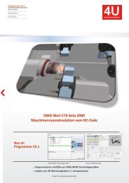
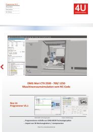
This is a multi-channel programming system for turning / milling machines with 3D machine room simulation. ● You create NC programs on the basis of an NC editor with machine macros and an integrated 2.5D CAD / CAM system. ● Templates are stored for different types of processing (bar / chuck ...). ● Program structures are generated automatically. ● The 3D machine space simulation shows the real machining process simultaneously. ● The actual implementation of the NC program is simulated. ● In the event of a collision, the relevant machine components and the associated NC blocks are displayed. What are the extensions of the V5.1 programmer? ● Project history and additional windows for further machine conditions ● Main and subprogram names are displayed in the simulation ● 3D blank (prismatic, rotationally symmetrical) is to be read in the STL format into the simulation ● The current workpiece is to be generated from the simulation as a 3D blank in the STL format ● Gaps can be measured in three dimensions ● NC block run times can be displayed as an EXCEL table
This is a multi-channel programming system for turning / milling machines with 3D machine room simulation.
● You create NC programs on the basis of an NC editor with machine macros and an integrated 2.5D CAD / CAM system.
● Templates are stored for different types of processing (bar / chuck ...).
● Program structures are generated automatically.
● The 3D machine space simulation shows the real machining process simultaneously.
● The actual implementation of the NC program is simulated.
● In the event of a collision, the relevant machine components and the associated NC blocks are displayed.
What are the extensions of the V5.1 programmer?
● Project history and additional windows for further machine conditions
● Main and subprogram names are displayed in the simulation
● 3D blank (prismatic, rotationally symmetrical) is to be read in the STL format into the simulation
● The current workpiece is to be generated from the simulation as a 3D blank in the STL format
● Gaps can be measured in three dimensions
● NC block run times can be displayed as an EXCEL table

Create successful ePaper yourself
Turn your PDF publications into a flip-book with our unique Google optimized e-Paper software.
4 | CAD/CAM operations
4.2 Computer-aided design (CAD)
Memo
For a turning contour, select the Rotation field. The following design screen appears.
1
2
3
4
37
CAD/CAM operations
Item
Description
1 Design toolbar
2 Design and machining sequence
3 Drawing plane
Icons
Description
Geometry generation:
Generation of auxiliary designs by means of
• Point definition
• Line definition
• Circle definition
Generate a contour:
• New contours, contour expansion, holes
• Macros: Undercut, recess, groove, circle and rectangle
• Point, line, arc, chamfers, radii
• Join with line, join with arc, close
Change a contour:
• Chamfers/radii, delete element, change radii, elongate
• Factor, offset, shift start / end, join/separate contour
• Working direction, soft on contour, attribute,
restore geometry elements
Edit:
Contours: Copy, mirror, shift, set zero point, rotate, delete
Measurement:
Contours: Measure distance, display element, measure
perimeter
A-D821UK-1_200420
37