E-mobility Technology Winter 2020
Electric vehicle technology news: Maintaining the flow of information for the e-mobility technology sector
Electric vehicle technology news: Maintaining the flow of information for the e-mobility technology sector

You also want an ePaper? Increase the reach of your titles
YUMPU automatically turns print PDFs into web optimized ePapers that Google loves.
e-<strong>mobility</strong> <strong>Technology</strong> International | Vol 7 | <strong>Winter</strong> <strong>2020</strong><br />
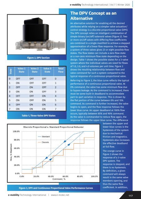
Figure 2, DPV Section<br />
Table 1, Three-Valve DPV States<br />
The DPV Concept as an<br />
Alternative<br />
Figure 3, DPV and Continuous Proportional Valve Performance Curves<br />
An alternative solution for enabling all the desired<br />
attributes while relying on a simpler valve actuation/<br />
control strategy is a discrete proportional valve (DPV).<br />
The DPV concept relies on intelligent combination of<br />
simple binary (on/off) solenoid valves (Figure 2). Two<br />
or more on/off valves with differing flow coefficients<br />
are combined in a single manifold to achieve a stepped<br />
approximation of a linear flow response. For example,<br />
a system of three valves gives 23 or eight possible flow<br />
states. The flow states can include a zero-flow state<br />
or a non-zero minimum flow state depending on the<br />
design. Table 1 shows the possible states for a 3-valve<br />
system where the individual valves are sized for flows<br />
of 1.0, 2.0, and 4.0 volumes per unit time. Figure 3<br />
shows the resulting relationship between flow and<br />
valve command for such a system compared to the<br />
typical response of a continuous proportional valve.<br />
Referring to Figure 3, the blue curve reflects the typical<br />
performance of a continuous proportional valve. At<br />
0% command, the valve has some minimum flow due<br />
to bypass leakage. As the command is increased, there<br />
must be some built-in deadband to accommodate<br />
part-to-part variation in response. This is shown by<br />
the flat portion of the curve between 0% and 15%<br />
command. As command is further increased, the valve<br />
begins to open, and the flow response follows the<br />
lower blue curve. An upper deadband at 100% flow<br />
occurs, typically between 85% and 90% command.<br />
As the valve is commanded to reduce flow again, the<br />
response follows the upper blue curve. The difference<br />
between the upper and<br />
lower blue curves is the<br />
hysteresis of the system<br />
due to mechanical<br />
friction and magnetics.<br />
Hysteresis also increases<br />
the effective deadband<br />
at full flow.<br />
The orange curve in<br />
Figure 3 shows the<br />
response of a 3-valve<br />
DPV system. The<br />
response is stepped, and<br />
there is no hysteresis.<br />
By definition, a given<br />
command will always<br />
result in the same valve<br />
members opening, and<br />
thus the same flow<br />
coefficient. In addition,<br />
e-<strong>mobility</strong> <strong>Technology</strong> International | www.e-motec.net<br />
117