Solar-supported heating networks in multi-storey residential buildings
Solar-supported heating networks in multi-storey residential buildings
Solar-supported heating networks in multi-storey residential buildings

Create successful ePaper yourself
Turn your PDF publications into a flip-book with our unique Google optimized e-Paper software.
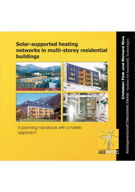
<strong>Solar</strong>-<strong>supported</strong> <strong>heat<strong>in</strong>g</strong><br />
<strong>networks</strong> <strong>in</strong> <strong>multi</strong>-<strong>storey</strong> <strong>residential</strong><br />
build<strong>in</strong>gs<br />
A plann<strong>in</strong>g handbook with a holistic<br />
approach<br />
Institute for Susta<strong>in</strong>able Technologies
<strong>Solar</strong>-<strong>supported</strong> <strong>heat<strong>in</strong>g</strong> <strong>networks</strong> <strong>in</strong> <strong>multi</strong>-<strong>storey</strong> <strong>residential</strong> build<strong>in</strong>gs<br />
A plann<strong>in</strong>g handbook with a holistic approach<br />
Authors:<br />
Christian F<strong>in</strong>k and Richard Riva<br />
Arbeitsgeme<strong>in</strong>schaft ERNEUERBARE ENERGIE – Institut für Nachhaltige Technologien<br />
www.aee.at<br />
Published by<br />
Title:<br />
<strong>Solar</strong>-<strong>supported</strong> <strong>heat<strong>in</strong>g</strong> <strong>networks</strong> <strong>in</strong> <strong>multi</strong>-<strong>storey</strong> <strong>residential</strong> build<strong>in</strong>gs<br />
A plann<strong>in</strong>g handbook with a holistic approach<br />
Authors:<br />
Ing. Christian F<strong>in</strong>k<br />
Ing. Richard Riva<br />
Compiled with the support of the:<br />
European Commission (with<strong>in</strong> the framework of the OPET Build<strong>in</strong>g, Contract No. NNE5/2002/94, DG TREN)<br />
Federal M<strong>in</strong>istry for Transport, Innovation and Technology<br />
Federal M<strong>in</strong>istry for the Economy and Labour<br />
Prov<strong>in</strong>ce of Styria (FA 6A Science and Research, A15 Residential Build<strong>in</strong>g Grants)<br />
City of Vienna (MA 22 Environment)<br />
ISBN 3-901425-11-X<br />
1st edition: 2004
Repr<strong>in</strong>t<strong>in</strong>g and translation, storage on data process<strong>in</strong>g equipment, also <strong>in</strong>clud<strong>in</strong>g excerpts thereof, is only permitted if<br />
the source is named and requires the express written approval of the authors.<br />
The content of the plann<strong>in</strong>g handbook "<strong>Solar</strong>-<strong>supported</strong> <strong>heat<strong>in</strong>g</strong> <strong>networks</strong> <strong>in</strong> <strong>multi</strong>-<strong>storey</strong> <strong>residential</strong> build<strong>in</strong>gs" was<br />
processed and compiled with the greatest care and accord<strong>in</strong>g to the best of our knowledge. Neither the publishers nor<br />
the authors shall assume liability for any <strong>in</strong>correct <strong>in</strong>formation or any damage which might occur as a result.<br />
Published by:<br />
Arbeitsgeme<strong>in</strong>schaft ERNEUERBARE ENERGIE GMBH<br />
A-8200 Gleisdorf, Feldgasse 19, Austria<br />
Cover photos:<br />
Top left: S.O.L.I.D., top right: Holleis <strong>Solar</strong>technik, bottom left: Teufel & Schwarz, bottom right: AEE INTEC<br />
Design, Typography & Reproduction:<br />
Ste<strong>in</strong>huber Infodesign, Graz<br />
Pr<strong>in</strong>ted by:<br />
Universitätsdruckerei Klampfer, Weiz<br />
2
1<br />
List of Contents<br />
2 Introduction 7<br />
2.1 Market penetration and potential of solar thermal systems <strong>in</strong> <strong>multi</strong>-<strong>storey</strong> <strong>residential</strong> build<strong>in</strong>gs<br />
7<br />
2.2 Innovations and the economic factor 8<br />
2.3 Motivation for this plann<strong>in</strong>g handbook 9<br />
3 A holistic approach to solar-<strong>supported</strong> energy supply systems 9<br />
3.1 Low average collector temperatures as an energy-related success factor 11<br />
3.2 Enhancement of the solar coverage and reduction <strong>in</strong> the auxiliary <strong>heat<strong>in</strong>g</strong> requirements as a<br />
result of very low heat losses <strong>in</strong> the system 12<br />
3.3 Greatest possible comfort for users 13<br />
3.4 Systems with the greatest possible water hygiene 14<br />
3.5 Exploit<strong>in</strong>g opportunities for reduc<strong>in</strong>g capital costs 14<br />
3.6 Low operat<strong>in</strong>g costs for users with the greatest possible reliability of supply 15<br />
4 <strong>Solar</strong> radiation 16<br />
4.1 Usable radiation capacity and annual usable radiation energy 16<br />
4.2 Distribution of solar radiation throughout one calendar year 17<br />
5 Heat<strong>in</strong>g requirements <strong>in</strong> <strong>multi</strong>-<strong>storey</strong> <strong>residential</strong> build<strong>in</strong>gs 19<br />
5.1 Determ<strong>in</strong><strong>in</strong>g <strong>heat<strong>in</strong>g</strong> requirements for domestic hot water 20<br />
5.1.1 Determ<strong>in</strong><strong>in</strong>g daily consumption 20<br />
5.1.1.1 Calculation of daily consumption for <strong>multi</strong>-<strong>storey</strong> <strong>residential</strong> build<strong>in</strong>gs 22<br />
5.1.1.2 Measurement of consumption <strong>in</strong> exist<strong>in</strong>g build<strong>in</strong>gs 24<br />
5.1.2 Consumption profile 25<br />
5.2 Determ<strong>in</strong><strong>in</strong>g <strong>heat<strong>in</strong>g</strong> requirements 27<br />
6 Structural <strong>in</strong>tegration of solar thermal systems <strong>in</strong> <strong>multi</strong>-<strong>storey</strong> <strong>residential</strong> build<strong>in</strong>gs<br />
28<br />
6.1 Roof <strong>in</strong>tegration of solar collectors 29<br />
3
6.2 Collector assembly with frame structures 32<br />
6.3 Façade <strong>in</strong>tegration of solar collectors 37<br />
6.3.1 Heat and moisture transport through wall structures 38<br />
6.3.2 Reduction of the effective U-value of the outside wall 41<br />
6.3.3 Coloured absorber layers 41<br />
6.4 Integration of energy storage units <strong>in</strong> build<strong>in</strong>gs 43<br />
7 System hydraulics 45<br />
7.1 Basic <strong>in</strong>formation about solar-<strong>supported</strong> energy supply systems 45<br />
7.1.1 Domestic water temperature and water hygiene – legionella bacteria 45<br />
7.1.2 Important characteristics for solar-<strong>supported</strong> energy supply systems 46<br />
7.1.2.1 The degree of solar coverage SD 46<br />
7.1.2.2 The specific solar thermal yield SE 48<br />
7.1.2.3 The annual degree of system utilisation SNutz<br />
7.1.3 Low-flow systems for solar thermal facilities <strong>in</strong> <strong>multi</strong>-<strong>storey</strong> <strong>residential</strong> build<strong>in</strong>gs – speed<br />
control and load<strong>in</strong>g strategies 49<br />
7.1.3.1 Low-flow vs. high-flow systems 49<br />
7.1.3.2 Speed control of primary and secondary circuits <strong>in</strong> the solar thermal system 51<br />
7.1.4 Collector <strong>in</strong>terconnections 53<br />
7.1.4.1 Large-area collectors 54<br />
7.1.4.2 Efficient collector pipework 54<br />
7.1.4.3 Expansion compensation 57<br />
7.1.4.4 Bleed<strong>in</strong>g and flush<strong>in</strong>g 58<br />
7.1.5 Stagnation behaviour of solar thermal systems 59<br />
7.1.5.1 Processes occurr<strong>in</strong>g dur<strong>in</strong>g the stagnation state 59<br />
7.1.5.2 Influence of collector and system hydraulics on stagnation behaviour 61<br />
7.1.5.3 Modified dimension<strong>in</strong>g of the membrane expansion tank 62<br />
7.1.5.4 Conclusions for the design of stagnation-proof systems <strong>in</strong> <strong>multi</strong>-<strong>storey</strong> <strong>residential</strong> build<strong>in</strong>gs<br />
64<br />
7.2 <strong>Solar</strong>-<strong>supported</strong> heat supply system designs 66<br />
4<br />
49
7.2.1 <strong>Solar</strong>-<strong>supported</strong> heat supply system designs based on the pr<strong>in</strong>ciple of 2-pipe <strong>networks</strong> 66<br />
7.2.1.1 Integrat<strong>in</strong>g the heat generators 66<br />
7.2.1.2 <strong>Solar</strong>-<strong>supported</strong> heat supply systems – two-pipe <strong>networks</strong> comb<strong>in</strong>ed with decentralised<br />
apartment units 67<br />
7.2.1.2.1 Apartment heat transfer units 69<br />
7.2.1.2.2 The heat distribution network 74<br />
7.2.1.3 <strong>Solar</strong>-<strong>supported</strong> heat supply systems – two-pipe <strong>networks</strong> comb<strong>in</strong>ed with decentralised<br />
domestic hot water storage units 77<br />
7.2.1.4 Advantages and disadvantages of solar-<strong>supported</strong> two-pipe heat <strong>networks</strong> 79<br />
7.2.2 <strong>Solar</strong>-<strong>supported</strong> heat systems with four-pipe <strong>networks</strong> 81<br />
7.2.2.1 <strong>Solar</strong>-<strong>supported</strong> heat supply systems us<strong>in</strong>g four-pipe <strong>networks</strong> comb<strong>in</strong>ed with s<strong>in</strong>gle storage<br />
tank systems 81<br />
7.2.2.2 <strong>Solar</strong>-<strong>supported</strong> heat systems: four-pipe <strong>networks</strong> comb<strong>in</strong>ed with two-tank systems 83<br />
8 Dimension<strong>in</strong>g 85<br />
8.1 Dimension<strong>in</strong>g of solar thermal systems 85<br />
8.1.1 Collector area and solar storage unit volume comb<strong>in</strong>ed with two-pipe <strong>networks</strong> 86<br />
8.1.1.1 Dimension<strong>in</strong>g nomogram with def<strong>in</strong>ed specific solar storage volume 87<br />
8.1.1.2 Dimension<strong>in</strong>g nomogram with variable specific solar storage volume 91<br />
8.1.1.3 Determ<strong>in</strong><strong>in</strong>g the <strong>in</strong>fluence of the <strong>in</strong>cl<strong>in</strong>ation and orientation of the collector area 93<br />
8.2 Dimension<strong>in</strong>g for security of supply 94<br />
8.2.1 Supply of space <strong>heat<strong>in</strong>g</strong> and domestic hot water 95<br />
8.2.2 Interaction between conventional heat generator and load equalisation storage tank 96<br />
8.2.2.1 Determ<strong>in</strong><strong>in</strong>g the overall volume of the energy storage unit 99<br />
8.2.3 Dimension<strong>in</strong>g of heat distribution network 101<br />
9 M<strong>in</strong>imisation of heat losses 102<br />
9.1 Energy storage tanks 102<br />
9.1.1 Heat losses from energy storage tanks 102<br />
9.1.2 S<strong>in</strong>gle-storage-unit systems <strong>in</strong>stead of <strong>multi</strong>-storage-unit systems 104<br />
9.2 Heat losses and pipework design 106<br />
5
10 Investment costs, grants and economic efficiency 110<br />
11 Plant management and monitor<strong>in</strong>g 113<br />
12 List of references 117<br />
6
2<br />
Introduction<br />
The thermal use of solar energy is a long and successful tradition <strong>in</strong> Austria. Thus <strong>in</strong> the last 20 years<br />
more than 2.5 million square metres of solar collector area have been <strong>in</strong>stalled <strong>in</strong> Austria (<strong>in</strong>clud<strong>in</strong>g<br />
swimm<strong>in</strong>g pool absorbers), which represents an average collector area of 0.3 m 2 per <strong>in</strong>habitant as of<br />
2002 (Fan<strong>in</strong>ger et al., 2003). With<strong>in</strong> the EU, only Greece has a slightly higher success rate. Today this<br />
collector area already covers more than one percent of Austrian low-temperature energy<br />
requirements.<br />
2.1<br />
Market penetration and potential of solar thermal systems <strong>in</strong> <strong>multi</strong>-<strong>storey</strong> <strong>residential</strong><br />
build<strong>in</strong>gs<br />
Motivated by the already high market penetration <strong>in</strong> the field of s<strong>in</strong>gle family homes (the figure is<br />
already much higher than ten percent), solar thermal systems are be<strong>in</strong>g implemented to an <strong>in</strong>creas<strong>in</strong>g<br />
extent <strong>in</strong> <strong>multi</strong>-<strong>storey</strong> <strong>residential</strong> build<strong>in</strong>gs. At the present moment <strong>in</strong> time, around 750 <strong>multi</strong>-<strong>storey</strong><br />
build<strong>in</strong>gs <strong>in</strong> Austria are equipped with thermal solar plants. In relation to the roughly two million<br />
pr<strong>in</strong>ciple residences <strong>in</strong> <strong>multi</strong>-<strong>storey</strong> <strong>residential</strong> build<strong>in</strong>gs (this corresponds to around 43% of the<br />
Austrian population) it can, therefore, be deduced that around 1% of all flat-owners or tenants are<br />
able to enjoy the advantages of a thermal solar plant (F<strong>in</strong>k, 2003).<br />
Figure 1: Efficient solar-<strong>supported</strong> heat supply system designs as standard <strong>in</strong> <strong>multi</strong>-<strong>storey</strong> <strong>residential</strong><br />
build<strong>in</strong>gs (picture source: BRAMAC Dachsysteme International, Upper Austria, Austria).<br />
On the one hand, potential applications rema<strong>in</strong> untapped and, on the other hand, particularly large<br />
solar thermal systems <strong>in</strong> <strong>multi</strong>-<strong>storey</strong> <strong>residential</strong> build<strong>in</strong>gs allow much lower specific system costs<br />
than, for example, small-scale plants. Thus solar systems do not only help to achieve economic<br />
<strong>heat<strong>in</strong>g</strong> prices, but they also reduce CO2 emissions <strong>in</strong> a cost-effective manner. The public sector has,<br />
<strong>in</strong> part, already recognised the potential and is <strong>in</strong>creas<strong>in</strong>gly back<strong>in</strong>g the use of solar energy (as well as<br />
other technologies) <strong>in</strong> new build<strong>in</strong>gs and <strong>in</strong> exist<strong>in</strong>g <strong>multi</strong>-<strong>storey</strong> <strong>residential</strong> build<strong>in</strong>gs to atta<strong>in</strong> climate<br />
protection goals. This is demonstrated by the grant<strong>in</strong>g of funds for the implementation of solar<br />
thermal systems <strong>in</strong> <strong>multi</strong>-<strong>storey</strong> build<strong>in</strong>gs <strong>in</strong> practically all the federal states of Austria as well as<br />
grants from various towns and communities.<br />
7
2.2<br />
Innovations and the economic factor<br />
Due to its long tradition of solar plants, a large number of the <strong>in</strong>novations to emerge <strong>in</strong> recent years<br />
orig<strong>in</strong>ated <strong>in</strong> Austria. Numerous <strong>in</strong>novations meant that, on the one hand, large solar thermal systems<br />
were implemented <strong>in</strong> <strong>residential</strong> build<strong>in</strong>gs <strong>in</strong> Austria and, on the other hand, Austrian companies have<br />
also constructed large plants <strong>in</strong> <strong>residential</strong> build<strong>in</strong>gs abroad. This <strong>in</strong>cludes the follow<strong>in</strong>g:<br />
• Development of large-area collectors and the implementation of crane assemblies<br />
• Industrial production of solar collectors<br />
• Aesthetically pleas<strong>in</strong>g and cost-effective <strong>in</strong>tegration of solar collectors <strong>in</strong> build<strong>in</strong>gs<br />
• Heat<strong>in</strong>g of solar non-potable water and <strong>heat<strong>in</strong>g</strong> support (comb<strong>in</strong>ed systems) <strong>in</strong> <strong>multi</strong>-<strong>storey</strong><br />
<strong>residential</strong> build<strong>in</strong>gs<br />
• Measur<strong>in</strong>g and analysis of solar-<strong>supported</strong> <strong>heat<strong>in</strong>g</strong> <strong>networks</strong> <strong>in</strong> <strong>multi</strong>-<strong>storey</strong> <strong>residential</strong><br />
build<strong>in</strong>gs<br />
• Def<strong>in</strong>ition of holistic solar-<strong>supported</strong> <strong>heat<strong>in</strong>g</strong> <strong>networks</strong><br />
• Innovative f<strong>in</strong>anc<strong>in</strong>g models for large solar thermal systems<br />
In the year 2001 around 240,000 m² of solar collector area was exported and around 160,000 m² <strong>in</strong><br />
2002 (this corresponds to 1.5 and 1.0 times the domestic market volume, respectively) (Fan<strong>in</strong>ger et<br />
al., 2003). This means that <strong>in</strong> these two years Austria accounted for around one quarter of the overall<br />
production of solar collectors <strong>in</strong> the EU. Apart from the economic success, the Austrian solar <strong>in</strong>dustry<br />
(domestic market and exports) provides nearly 3,000 jobs.<br />
Figure 2: 1.248 m² solar thermal collector area produced by an Austrian manufacturer on the roof of<br />
eight <strong>multi</strong>-<strong>storey</strong> <strong>residential</strong> build<strong>in</strong>gs <strong>in</strong> Hels<strong>in</strong>ki (picture source: AEE INTEC).<br />
2.3<br />
Motivation for this plann<strong>in</strong>g handbook<br />
Extensive know-how about solar-<strong>supported</strong> <strong>heat<strong>in</strong>g</strong> <strong>networks</strong> <strong>in</strong> <strong>multi</strong>-<strong>storey</strong> <strong>residential</strong> build<strong>in</strong>gs is<br />
available at selected sites <strong>in</strong> Austria. Apart from specific developments with regard to system<br />
components, numerous further developments have been made <strong>in</strong> the past few years with regard to<br />
holistic system behaviour and <strong>in</strong>tegration <strong>in</strong>to build<strong>in</strong>gs. Extensive tests based on measur<strong>in</strong>g<br />
techniques provided important empirical values from practical applications. It is the major goal of this<br />
plann<strong>in</strong>g handbook to focus this specific know-how and also to make it available to all the actors and<br />
<strong>multi</strong>pliers.<br />
8
The aim of this book is to present a holistic approach to the plann<strong>in</strong>g, implementation and<br />
management of solar-<strong>supported</strong> <strong>heat<strong>in</strong>g</strong> <strong>networks</strong> <strong>in</strong> <strong>multi</strong>-<strong>storey</strong> <strong>residential</strong> build<strong>in</strong>gs. In the short<br />
term, the declared goal has to be to def<strong>in</strong>e solar-<strong>supported</strong> <strong>heat<strong>in</strong>g</strong> <strong>networks</strong> as a standard for new<br />
<strong>multi</strong>-<strong>storey</strong> <strong>residential</strong> build<strong>in</strong>gs and to step up activities with regard to exist<strong>in</strong>g build<strong>in</strong>gs. After all,<br />
every renovation (structural eng<strong>in</strong>eer<strong>in</strong>g or facility management) that does not employ a solar system<br />
represents a lost opportunity, <strong>in</strong> terms of reduc<strong>in</strong>g the operat<strong>in</strong>g costs and C02 emissions, until the<br />
next renovation (generally a period of several decades).<br />
Figure 3: 274 m² solar thermal collector area produced by an Austrian manufacturer on a hous<strong>in</strong>g<br />
estate with 197 apartments (picture source: Kappei SOLAR FUTURE TECHNIK, Germany).<br />
The high technical standard of modern solar-<strong>supported</strong> <strong>heat<strong>in</strong>g</strong> <strong>networks</strong> means there is no reason to<br />
delay a decision <strong>in</strong> favour of a solar thermal system. Moreover, the impend<strong>in</strong>g shortage <strong>in</strong> the global<br />
energy supply and the already tense situation with regard to the global climate as a result of burn<strong>in</strong>g<br />
fossil fuels also encourages this decision.<br />
3<br />
A holistic approach to solar-<strong>supported</strong> energy supply systems<br />
In various studies, the product and <strong>in</strong>stallation quality of solar thermal systems has been analysed <strong>in</strong><br />
exist<strong>in</strong>g plants. Thus, for example, 75 solar energy plants <strong>in</strong> Vorarlberg were exam<strong>in</strong>ed and their<br />
technical condition evaluated (Schlader, 2002). 25% of the plants were <strong>in</strong> perfect condition, 50%<br />
revealed slight problems and the rema<strong>in</strong><strong>in</strong>g 25% of the plants displayed considerable technical defects<br />
which had an impact on the plant’s operational efficiency.<br />
It is probable that these results are not only true of Vorarlberg (Austria) but can be applied to other<br />
Austrian federal states <strong>in</strong> a correspond<strong>in</strong>g manner. It does, however, have to be said that this result is<br />
not specific to solar thermal systems but rather describes the prevalent plann<strong>in</strong>g and <strong>in</strong>stallation<br />
quality of conventional <strong>heat<strong>in</strong>g</strong> systems as well. In contrast to conventional <strong>heat<strong>in</strong>g</strong> plants, however,<br />
solar thermal systems are subjected to tests and measurements of this k<strong>in</strong>d. Experience shows,<br />
moreover, that as a result of test<strong>in</strong>g solar thermal systems it was also frequently possible to detect<br />
defects <strong>in</strong> conventional <strong>heat<strong>in</strong>g</strong> supply systems which would otherwise not have been discovered. In<br />
many cases this led to the first attempts at def<strong>in</strong><strong>in</strong>g holistic solar-<strong>supported</strong> <strong>heat<strong>in</strong>g</strong> <strong>networks</strong>.<br />
9
Figure 4: Efficient solar-<strong>supported</strong> <strong>heat<strong>in</strong>g</strong> <strong>networks</strong> demand a holistic approach to the plann<strong>in</strong>g,<br />
implementation and management. This <strong>in</strong>cludes the solar thermal system (left), the conventional<br />
<strong>heat<strong>in</strong>g</strong> systems (middle, <strong>in</strong> this case biomass) as well as the heat distribution system (right) (picture<br />
source: AEE INTEC).<br />
One mistake frequently made <strong>in</strong> the plann<strong>in</strong>g and implementation of solar thermal systems is that the<br />
solar thermal system is considered <strong>in</strong> isolation with regard to <strong>in</strong>tegration <strong>in</strong>to the build<strong>in</strong>g, plant<br />
hydraulics and energy sav<strong>in</strong>gs. The <strong>in</strong>teraction between the architecture, the solar thermal system,<br />
conventional heat generators, heat distribution and the heat supply to the consumers (domestic hot<br />
water, space <strong>heat<strong>in</strong>g</strong>) is not taken <strong>in</strong>to sufficient consideration. Likewise the subjective needs and<br />
requirements of the user are frequently not adequately considered.<br />
Experience has shown that all of these requirements have to be acted on dur<strong>in</strong>g the plann<strong>in</strong>g phase<br />
(<strong>in</strong>tegral plann<strong>in</strong>g) and given utmost attention dur<strong>in</strong>g implementation. This requires procedures<br />
adapted both to the plann<strong>in</strong>g and implementation process, a holistic approach and the early <strong>in</strong>clusion<br />
of all of those concerned with energy <strong>in</strong> the plann<strong>in</strong>g, implementation and plant management process.<br />
In this way special requirements can be recognised <strong>in</strong> good time, <strong>in</strong>terfaces can be clearly def<strong>in</strong>ed and<br />
areas of competence determ<strong>in</strong>ed (<strong>in</strong>clud<strong>in</strong>g warranties). In this respect, Figure 5 provides a<br />
procedural diagram as an example of the realisation of holistic and <strong>in</strong>tegral solar-<strong>supported</strong> <strong>heat<strong>in</strong>g</strong><br />
supply systems.<br />
Aesthetically Pleas<strong>in</strong>g and<br />
Cost-effective Integration<br />
� Collector Area<br />
� Store<br />
� Equipment<br />
Overall Heat Supply Concept<br />
�<br />
�<br />
�<br />
�<br />
�<br />
<strong>Solar</strong> Plant<br />
Conv. Heater<br />
Distribution Pipel<strong>in</strong>e<br />
Heat Transfer Net<br />
Domestic Hot Water<br />
Integral Plann<strong>in</strong>g<br />
Team Meet<strong>in</strong>gs<br />
Detailed Plann<strong>in</strong>g<br />
� Selection of Components<br />
and Dimension<strong>in</strong>g<br />
� Call for Tender<br />
10<br />
Simultaneous Involvement<br />
of Plann<strong>in</strong>g Team<br />
�<br />
�<br />
�<br />
�<br />
�<br />
Build<strong>in</strong>g Owner<br />
Architects<br />
Civil Eng<strong>in</strong>eers<br />
Caretaker of Technical<br />
Systems <strong>in</strong> Build<strong>in</strong>g<br />
System Operator<br />
Operation Management<br />
�<br />
�<br />
�<br />
�<br />
Order<strong>in</strong>g and Installation<br />
��Investigation<br />
of Possible<br />
Ways to Reduce Costs<br />
��Contract<br />
and Careful<br />
Installation<br />
��Hydraulic<br />
Adjustments<br />
Figure 5: Method for the holistic use of applied solar-<strong>supported</strong> <strong>heat<strong>in</strong>g</strong> systems.<br />
F<strong>in</strong>al Adjustment<br />
Cont<strong>in</strong>uous System Control<br />
Prepare Proof of <strong>Solar</strong> Yield<br />
Heat Cost Calculation<br />
In the follow<strong>in</strong>g, aspects will be discussed which, on the one hand, describe the <strong>in</strong>terrelations and, on<br />
the other hand, illustrate the absolute necessity for a holistic approach to solar-<strong>supported</strong> <strong>heat<strong>in</strong>g</strong><br />
supply systems.
3.1<br />
Low average collector temperatures as an energy-related success factor<br />
The average collector temperature ((T<strong>in</strong>let+Toutlet)/2) is the decisive value for the present high-quality<br />
collectors to atta<strong>in</strong> high solar yields throughout the year. The lower the average collector temperature,<br />
the higher the efficiency rate of the collector and thus the solar yield. Without a doubt, it is wrong to<br />
believe that the demand for the lowest possible average collector temperature can only be adequately<br />
achieved by the solar thermal system alone.<br />
It is rather the case that apart from the dimension<strong>in</strong>g of the collector area, other aspects and<br />
parameters determ<strong>in</strong>e the temperature level at the collector:<br />
• Type and manner of <strong>in</strong>tegration of the conventional heat generator<br />
• Pr<strong>in</strong>ciple and dimension<strong>in</strong>g of domestic water <strong>heat<strong>in</strong>g</strong><br />
• Pr<strong>in</strong>ciple and dimension<strong>in</strong>g of space <strong>heat<strong>in</strong>g</strong> supply<br />
• Dimension<strong>in</strong>g of the storage unit volume available for the solar thermal plant<br />
• Mix<strong>in</strong>g rate of energy storage unit (water amounts, geometries of storage units, etc.)<br />
The <strong>in</strong>fluence of the <strong>in</strong>teraction of the overall <strong>heat<strong>in</strong>g</strong> supply system on the average collector<br />
temperature, and thus on the efficiency of the collector, can be seen by way of example <strong>in</strong> Figure 6.<br />
Heat<strong>in</strong>g supply concepts adapted to the requirements of solar energy plants achieve much lower<br />
average collector temperatures and thus higher collector efficiencies <strong>in</strong> all operat<strong>in</strong>g po<strong>in</strong>ts.<br />
η 0<br />
1,00<br />
0,90<br />
0,80<br />
0,70<br />
0,60<br />
0,50<br />
0,40<br />
0,30<br />
0,20<br />
0,10<br />
A<br />
Collector Efficiency at Typical Operat<strong>in</strong>g Po<strong>in</strong>ts<br />
B<br />
0,00<br />
0,00 0,02 0,04 0,06 0,08<br />
(Tkm-Tu)/G [Km²/W]<br />
0,10 0,12 0,14 0,16<br />
11<br />
Conditions Given:<br />
Collector Data: c 0=0,8<br />
c 1=0.33 [W/m²K]<br />
c 2=0.012 [W/m²K²]<br />
Surround<strong>in</strong>g Temperature = 20 [°C]<br />
Average Collector Temperature A = 45 [K]<br />
Average Collector Temperature B = 60 [K]<br />
Radiation on the Collector Surface = 800 [W/m²]<br />
Figure 6: The <strong>in</strong>fluence of the temperature on the achievable collector efficiency. An Adapted holistic<br />
<strong>heat<strong>in</strong>g</strong> systems with lower mean temperature (operat<strong>in</strong>g po<strong>in</strong>t A) achieve essentially higher collector<br />
efficiency than for the example a solar thermal system with high return temperatures <strong>in</strong> the heat<br />
distribution system (operat<strong>in</strong>g po<strong>in</strong>t B).<br />
Only the <strong>in</strong>tegration of heat generators adapted to the needs of solar thermal systems or their heat<br />
emission components permits low average collector temperatures and thus the highest possible solar<br />
yields.
3.2<br />
Enhancement of the solar coverage and reduction <strong>in</strong> auxiliary <strong>heat<strong>in</strong>g</strong> requirements as a<br />
result of very low heat losses <strong>in</strong> the system<br />
It is not only the solar yield which is of decisive significance <strong>in</strong> holistic considerations but also the<br />
overall annual system utilisation rate. Highly efficient solar thermal systems lose their relevance <strong>in</strong> the<br />
case of a thermally <strong>in</strong>efficient (lossy) residual system, which is reflected <strong>in</strong> very low solar coverage<br />
rates. Figure 7 shows the example of the system losses of a solar-<strong>supported</strong> <strong>heat<strong>in</strong>g</strong> supply system<br />
from the heat generators (energy <strong>in</strong>put – without any losses dur<strong>in</strong>g energy conversion) to the<br />
consumers (useful energies for domestic hot water and space <strong>heat<strong>in</strong>g</strong>). On the basis of numerous<br />
measurements, it becomes clear that considerable heat losses occur <strong>in</strong> the system sections of heat<br />
storage and heat distribution, which <strong>in</strong> the case of exceptionally <strong>in</strong>efficient <strong>heat<strong>in</strong>g</strong> supply systems can<br />
also lead to system efficiencies below 50%.<br />
Energy Flow [%]<br />
100%<br />
90%<br />
80%<br />
70%<br />
60%<br />
50%<br />
40%<br />
30%<br />
20%<br />
10%<br />
0%<br />
Losses<br />
Collector Circuit<br />
4%<br />
<strong>Solar</strong> Input <strong>in</strong>to<br />
the System <strong>Solar</strong> Yield<br />
<strong>in</strong> the Store<br />
36%<br />
32%<br />
64% 64%<br />
Additional Heat<br />
<strong>in</strong>to System<br />
Additional Heat<br />
<strong>in</strong>to Store<br />
Losses<br />
Heat Store<br />
6% 2%<br />
27%<br />
Removal from<br />
Heat Store DHW<br />
63%<br />
Removal from<br />
Heat Store H<br />
12<br />
Losses<br />
Heat Exchanger<br />
19%<br />
21%<br />
Useful Energy DHW<br />
48%<br />
Useful Energy H<br />
Energy Input Into the Store Out of the Store H and DHW<br />
<strong>in</strong> the Homes<br />
Losses H-,<br />
DHW-Distribution Net<br />
21%<br />
Useful Energy DHW<br />
48%<br />
Useful Energy H<br />
Useful Energy<br />
H and DHW<br />
Figure 7: Exemplary description of the system losses of a solar-<strong>supported</strong> <strong>heat<strong>in</strong>g</strong> supply system (from<br />
the heat distributor to the end user with an annual degree of system utilisation of 69%).<br />
On the one hand, this problem has to be tackled by appropriate system hydraulics and, on the other<br />
hand, by an improved design of the thermal <strong>in</strong>sulation standard.<br />
• Selection of simple system hydraulics with conceptionally reduced system temperatures<br />
avoid<strong>in</strong>g pipework<br />
• Position<strong>in</strong>g of the energy storage unit at the shortest possible distances from the site of heat<br />
generation (solar collectors, conventional source of heat/energy) and to the consumers<br />
(domestic hot water and space <strong>heat<strong>in</strong>g</strong>)<br />
• Avoidance of outside pipework<br />
• Selection of one-storage-tank system without storage unit batteries<br />
• Improved standards with regard to storage unit <strong>in</strong>sulation<br />
• Insulation of all <strong>in</strong>door pipework <strong>in</strong> accordance with the requirements of ÖNORM M7580<br />
• Improved <strong>in</strong>sulation standards for outdoor pipework<br />
• Use of <strong>in</strong>sulation for valves and fitt<strong>in</strong>gs<br />
31% System<br />
Losses<br />
69% Annual System<br />
Utilisation Rate
3.3<br />
Greatest possible comfort for users<br />
Build<strong>in</strong>gs are basically constructed for the people who live <strong>in</strong> them or their users. For this reason,<br />
subjective comfort and liv<strong>in</strong>g habits should not be prescribed by eng<strong>in</strong>eers but rather def<strong>in</strong>ed by the<br />
users themselves.<br />
Figure 8: The comfort is <strong>in</strong>creased by the utilisation of the solar thermal system and not the other way<br />
around (picture source: Ultimate Lifestyle).<br />
This aspect should be given major attention <strong>in</strong> the plann<strong>in</strong>g and implementation phase of facility<br />
management plants and should cover the follow<strong>in</strong>g po<strong>in</strong>ts:<br />
• An important comfort parameter is hav<strong>in</strong>g domestic hot water on tap as and when required<br />
• Standardized calculation pr<strong>in</strong>ciples are important. In this respective, the subjective feel<strong>in</strong>g of<br />
comfort experienced by <strong>in</strong>dividuals should not be forgotten. This means that room<br />
temperatures below or above standardised levels should be possible, as required by the<br />
occupants.<br />
• The occupants' different lifestyles also <strong>in</strong>volve different rest and active phases. This means<br />
that the usual reduction of <strong>heat<strong>in</strong>g</strong> levels dur<strong>in</strong>g the night should be reconsidered <strong>in</strong> the light<br />
of this aspect.<br />
• In modern <strong>heat<strong>in</strong>g</strong> supply plants the selection of <strong>heat<strong>in</strong>g</strong> limit temperatures can be<br />
determ<strong>in</strong>ed by the users themselves.<br />
Build<strong>in</strong>g equipment and appliances which make use of renewable sources of energy or which enhance<br />
energy efficiency are frequently associated with restrictions <strong>in</strong> terms of comfort. The fact that this is<br />
not actually true and that an <strong>in</strong>crease <strong>in</strong> comfort is <strong>in</strong> fact achieved by the use of renewable sources<br />
of energy as a result of the system (as well as psychologically) has to be conveyed to the end<br />
consumer more explicitly <strong>in</strong> the future. In this respect, it should be mentioned that with <strong>in</strong>telligent<br />
system solutions an <strong>in</strong>crease <strong>in</strong> comfort is not automatically the same as a higher consumption of<br />
energy.<br />
13
3.4<br />
Systems with the greatest possible water hygiene<br />
Water is life. Unfortunately microorganisms are also aware of this fact. Whilst cold water pipes are<br />
almost completely free of microorganism contam<strong>in</strong>ation represent<strong>in</strong>g a health risk, the conditions <strong>in</strong><br />
hot water pipes are ideal for such contam<strong>in</strong>ation. Deposits of limescale, corrosion products, rubber<br />
washers, rema<strong>in</strong>s of hemp and fitt<strong>in</strong>gs create ideal conditions. As a consequence, it is necessary to<br />
design potable water <strong>heat<strong>in</strong>g</strong> systems <strong>in</strong> such a way that bacteria which represent a health risk<br />
(trigger<strong>in</strong>g legionnaires’ disease or Pontiac fever) will die quickly. S<strong>in</strong>ce bacteria are strongly<br />
dependent on temperature for growth requirements and life span, potable water <strong>heat<strong>in</strong>g</strong> systems<br />
have to be designed so that there is absolutely no risk of <strong>in</strong>fection for users.<br />
As with conventional plants for non-potable water <strong>heat<strong>in</strong>g</strong>, the design of solar-<strong>supported</strong> systems has<br />
to be adapted to these needs. In cases where there is absolutely no risk it is possible to select a<br />
system configuration which will not impair the solar yields and system efficiency. System solutions of<br />
this k<strong>in</strong>d (cont<strong>in</strong>uous flow water heaters or storage tanks) are available on the market for all different<br />
k<strong>in</strong>ds of applications for solar thermal plants.<br />
3.5<br />
Figure 9: Hygienic supply of domestic hot water and the highest comfort are a<br />
central issues by solar-<strong>supported</strong> <strong>heat<strong>in</strong>g</strong> <strong>networks</strong> (picture source: Photo<br />
Alto).<br />
Exploit<strong>in</strong>g opportunities for reduc<strong>in</strong>g capital costs<br />
A holistic approach to solar-<strong>supported</strong> <strong>heat<strong>in</strong>g</strong> supply systems is, however, not the only aspect which<br />
offers enormous potential for reduc<strong>in</strong>g capital costs; structural eng<strong>in</strong>eer<strong>in</strong>g <strong>in</strong>tegration is also of great<br />
significance. In both fields the guid<strong>in</strong>g pr<strong>in</strong>ciple is to make use of any potential synergies. However, to<br />
be able to recognise these synergies and then implement them, holistic plann<strong>in</strong>g which recognises<br />
<strong>in</strong>terfaces and cooperation amongst the different companies and experts <strong>in</strong>volved <strong>in</strong> the build<strong>in</strong>g<br />
project is a necessity.<br />
• Integral plann<strong>in</strong>g might lead to higher plann<strong>in</strong>g costs but, as a whole, it reduces the capital<br />
costs quite considerably.<br />
• The <strong>in</strong>tegration of solar collectors <strong>in</strong>to a build<strong>in</strong>g (roof or facade <strong>in</strong>tegration, use of collectors<br />
as shad<strong>in</strong>g elements) represents an additional benefit. Apart from the fact that a separate<br />
roof structure is not needed, conventional weather protection (roof cover<strong>in</strong>g or façade<br />
construction) is not required for the area covered by collectors.<br />
• The space requirements and the specific costs of the domestic <strong>in</strong>stallations can be reduced by<br />
us<strong>in</strong>g them for more than one purpose (heat storage unit, pressure ma<strong>in</strong>tenance plants etc.).<br />
• The space requirements of domestic <strong>in</strong>stallations (storage unit, conventional source of heat,<br />
pipework, other system components, etc.) have to be taken <strong>in</strong>to consideration <strong>in</strong> good time.<br />
• An attempt should be made to use energy shafts and any necessary (empty) pipework more<br />
than once.<br />
14
3.6<br />
• Outdoor or underground pipework is particularly cost-<strong>in</strong>tensive because it is of a special<br />
design and considerable cost reductions can be achieved if such structures are not used.<br />
• Simple <strong>heat<strong>in</strong>g</strong> supply concepts, adapted to the actual needs of the users, are as a rule less<br />
cost-<strong>in</strong>tensive than various types of hydraulic pipework.<br />
• Only use standard fitt<strong>in</strong>gs which are really needed for well-tuned hydraulics.<br />
• One s<strong>in</strong>gle control device for the entire <strong>heat<strong>in</strong>g</strong> supply leads to <strong>in</strong>terface reductions and<br />
reduces the capital costs.<br />
• The comb<strong>in</strong>ed design of the functions which follow "regulation" and "operational and yield<br />
control" results <strong>in</strong> lower capital costs.<br />
• Exam<strong>in</strong>ation of all the fund<strong>in</strong>g possibilities from public sources (direct grants, low-cost loans<br />
or annuity allowances) before commenc<strong>in</strong>g build<strong>in</strong>g work.<br />
Low operat<strong>in</strong>g costs for users with the greatest possible reliability of supply<br />
It is difficult to operate solar thermal plants <strong>in</strong> the form of monovalent <strong>heat<strong>in</strong>g</strong> supply systems which<br />
is the reason why it is impossible to dispense with a conventional heat generator. From an economic<br />
po<strong>in</strong>t of view, therefore, solar thermal systems are viable as a result of reduc<strong>in</strong>g the operat<strong>in</strong>g costs<br />
and not the capital costs. In the <strong>residential</strong> build<strong>in</strong>g sector <strong>in</strong> particular, where the end consumer<br />
often prefers low capital costs to low long-term operat<strong>in</strong>g costs, a great deal of work has to be done<br />
by consultants and builders to provide more <strong>in</strong>formation. This consideration is becom<strong>in</strong>g more<br />
important provided that the <strong>in</strong>creas<strong>in</strong>g cost of fossil forms of energy is also taken <strong>in</strong>to account. Figure<br />
10 shows the development forecast by energy experts (Campbell et al., 1998) for the total world oil<br />
production. In accordance with this, the upper limits have already been exceeded <strong>in</strong> some regions rich<br />
<strong>in</strong> oil. As far as world production is concerned, this "Big Rollover" is expected <strong>in</strong> the middle of the<br />
current decade. In the light of this development, those responsible for the construction of <strong>residential</strong><br />
build<strong>in</strong>gs will have to take measures right now so that the anticipated rise <strong>in</strong> energy prices will not<br />
lead to an explosion <strong>in</strong> the occupants' operat<strong>in</strong>g costs and also to ensure the security of the future<br />
energy supply.<br />
Figure 10: The development of the world oil production. Documented until 1998, prognosticated until<br />
2050 (picture source: Campell et al., 1998).<br />
The follow<strong>in</strong>g <strong>in</strong>clude some approaches for reduc<strong>in</strong>g operat<strong>in</strong>g costs and secur<strong>in</strong>g the supply:<br />
15
4<br />
• Reduction of <strong>heat<strong>in</strong>g</strong> requirements as a result of implement<strong>in</strong>g a correspond<strong>in</strong>g thermal<br />
<strong>in</strong>sulation standard <strong>in</strong> new build<strong>in</strong>gs or when renovat<strong>in</strong>g us<strong>in</strong>g ventilation heat recovery<br />
• Reduction of domestic hot water requirements by us<strong>in</strong>g water-sav<strong>in</strong>g fitt<strong>in</strong>gs<br />
• Heat<strong>in</strong>g supply systems with low heat losses and the highest possible annual total efficiency<br />
factor<br />
• <strong>Solar</strong>-<strong>supported</strong> <strong>heat<strong>in</strong>g</strong> supply systems with the highest possible solar coverage<br />
• Coverage of rema<strong>in</strong><strong>in</strong>g <strong>heat<strong>in</strong>g</strong> requirements by renewable forms of energy (e. g. <strong>heat<strong>in</strong>g</strong> with<br />
pellets and chips)<br />
• Regular monitor<strong>in</strong>g (<strong>in</strong> large-scale plants automated plant monitor<strong>in</strong>g) of whether the <strong>heat<strong>in</strong>g</strong><br />
supply system is function<strong>in</strong>g and adherence to the necessary ma<strong>in</strong>tenance <strong>in</strong>tervals<br />
• Use of energy-sav<strong>in</strong>g household appliances<br />
• Use of ra<strong>in</strong> water<br />
• Information for occupants regard<strong>in</strong>g the <strong>in</strong>fluence of user behaviour<br />
<strong>Solar</strong> radiation<br />
The sun is the central supplier of energy <strong>in</strong> our solar system. It is a ball of gaseous substance <strong>in</strong> the<br />
centre of which nuclear reactions are constantly tak<strong>in</strong>g place. The surface of the earth receives<br />
around half its exoatmospheric radiation energy from the sun <strong>in</strong> the course of a year because when it<br />
penetrates the earth’s atmosphere some of the radiation is absorbed or reflected <strong>in</strong>to space. However,<br />
the radiation energy which reaches the cont<strong>in</strong>ents still amounts to 219,000,000 billion kWh per<br />
annum. This represents 2,500 times the current global energy requirements.<br />
4.1<br />
Usable radiation capacity and annual usable radiation energy<br />
On a clear and cloudless sunny day the radiation capacity may reach up to 1,000 W/m².<br />
Measurements have revealed that if the sky is slightly overcast but the sun can still be seen it is<br />
possible to achieve a top power of 1,200 W/m² <strong>in</strong> the form of reflections from the clouds.<br />
What is known as global radiation consists of direct and diffuse radiation. Direct solar radiation is the<br />
fraction that arrives from the direction of the sun relatively unimpeded, whilst diffuse radiation<br />
reaches the surface of the earth from all directions uniformly. Diffuse radiation is the result of<br />
scatter<strong>in</strong>g processes <strong>in</strong> the atmosphere. This fraction depends greatly on the time of year, the level of<br />
cloud cover and on climatic and geographical conditions as well as on altitude. Depend<strong>in</strong>g on these<br />
parameters, the fraction of diffuse radiation fluctuates <strong>in</strong> Central Europe between 40% <strong>in</strong> May and up<br />
to 80% <strong>in</strong> December.<br />
The sunsh<strong>in</strong>e duration and the radiation <strong>in</strong>tensity depend on the time of the year, weather conditions<br />
and naturally on the geographical location. Thus the annual total global radiation <strong>in</strong> the sunniest<br />
regions of the earth can amount to more than 2,200 kWh/m².<br />
In Austria, annual solar radiation is between 1,000 and 1,400 kWh/m². On the one hand, these<br />
differences can be expla<strong>in</strong>ed by the large range of altitudes (high altitudes mean hardly any days of<br />
fog) and on the regional differences <strong>in</strong> the weather which are considerable.<br />
Figure 11 shows the mean long-term total annual global radiation on a horizontal surface for different<br />
regions <strong>in</strong> Austria. From this it can be seen that although there are privileged areas the use of solar<br />
energy would make absolute sense <strong>in</strong> every region of Austria. This statement can be illustrated by one<br />
simple example. Basically the southern side of the Alps would appear to be more favoured <strong>in</strong> terms of<br />
16
sunsh<strong>in</strong>e, but it should be remembered that the prov<strong>in</strong>ce of Upper Austria, which is located on the<br />
northern side of the Alps, has the highest density of solar <strong>in</strong>stallations (0.3 m² flat collector per<br />
<strong>in</strong>habitant) <strong>in</strong> Austria (status: end of 2002).<br />
Average Annual Radiation <strong>in</strong> kWh/m²<br />
Figure 11: Annual mean long-term total global radiation on a horizontal surface for different regions <strong>in</strong><br />
Austria <strong>in</strong> kWh/m².<br />
The availability of suitable sets of weather data for the design of the solar thermal systems is very<br />
good <strong>in</strong> Austria. The simulation programs most frequently used for the design of solar thermal<br />
systems (TSOL, 2003; POLYSUN, 2003) have extensive databases with sets of weather data for the<br />
largest towns and cities <strong>in</strong> Austria.<br />
4.2<br />
Distribution of solar radiation throughout one calendar year<br />
The average duration of sunsh<strong>in</strong>e <strong>in</strong> Austria is approximately 2,000 hours of which around three<br />
quarters is recorded <strong>in</strong> the summer (see Figure 12). In contrast, <strong>in</strong> the months with the highest<br />
energy demand (November to February) only one sixth of the overall annual energy is irradiated.<br />
17
Radiation [kWh/m² and Day]<br />
9,00<br />
8,50<br />
8,00<br />
7,50<br />
7,00<br />
6,50<br />
6,00<br />
5,50<br />
5,00<br />
4,50<br />
4,00<br />
3,50<br />
3,00<br />
2,50<br />
2,00<br />
1,50<br />
1,00<br />
0,50<br />
0,00<br />
Jän Feb Mär Apr Mai Jun Jul Aug Sep Okt Nov Dez<br />
18<br />
Total Radiation: 1,120 kWh/m² a<br />
Figure 12: <strong>Solar</strong> radiation on a horizontal area <strong>in</strong> Graz, Austria, created from mean month<br />
temperatures generated from values over many years.<br />
The annual course of solar radiation <strong>in</strong> accordance with the seasons shows clear advantages for the<br />
use of solar energy for applications where major consumption is <strong>in</strong> the summer months or for other<br />
applications which have constant consumption throughout the year. However, <strong>in</strong> the transitional<br />
period (March to May and September to October), the Austrian climate permits high irradiation rates,<br />
which provides favourable conditions for solar support of space <strong>heat<strong>in</strong>g</strong> applications.<br />
Figure 13 shows the course of average annual global irradiation <strong>in</strong> three areas at a different <strong>in</strong>cl<strong>in</strong>e<br />
(90°, 45°, 0°) for locations <strong>in</strong> Graz. The highest annual irradiation of 1,260 kWh/m² is on an area with<br />
an <strong>in</strong>cl<strong>in</strong>e of 45°, followed by the horizontal area with 1,120 kWh/m². The area <strong>in</strong>cl<strong>in</strong>ed at 90° is<br />
slightly less favourable with annual irradiation amount<strong>in</strong>g to 900 kWh/m².
Radiation [kWh/m² and Month]<br />
180<br />
170<br />
160<br />
150<br />
140<br />
130<br />
120<br />
110<br />
100<br />
90<br />
80<br />
70<br />
60<br />
50<br />
40<br />
30<br />
20<br />
10<br />
0<br />
Jan Feb Mar Apr May Jun Jul Aug Sep Oct Nov Dec<br />
19<br />
Radiation on a Horizontal Surface<br />
Radiation on a Surface at 45°<br />
Radiation on a Surface at 90°<br />
Figure 13: Average annual global irradiation <strong>in</strong> three areas at a different <strong>in</strong>cl<strong>in</strong>e, Graz, Austria.<br />
The seasonal course of irradiation is of <strong>in</strong>terest, <strong>in</strong> addition to the annual absolute global irradiation<br />
figures. With respect to the three <strong>in</strong>cl<strong>in</strong>es compared, the highest radiation on a horizontally <strong>in</strong>cl<strong>in</strong>ed<br />
area was achieved <strong>in</strong> May, June and July and the lowest radiation <strong>in</strong> the months of January, February,<br />
October, November and December. In this respect, the vertical area displays almost constant radiation<br />
course throughout the year. The area with an <strong>in</strong>cl<strong>in</strong>e of 45°, however, has advantages for all-year<br />
applications compared to the other two <strong>in</strong>cl<strong>in</strong>es. In practice this means adjust<strong>in</strong>g the <strong>in</strong>cl<strong>in</strong>e of<br />
collector elements to suit the consumption profile.<br />
5<br />
Heat<strong>in</strong>g requirements <strong>in</strong> <strong>multi</strong>-<strong>storey</strong> <strong>residential</strong> build<strong>in</strong>gs<br />
To avoid the undesirable over-siz<strong>in</strong>g or under-siz<strong>in</strong>g of solar thermal plants, it is important to have as<br />
precise a knowledge as possible of the energy requirements when design<strong>in</strong>g the solar-<strong>supported</strong><br />
<strong>heat<strong>in</strong>g</strong> <strong>networks</strong>. The <strong>heat<strong>in</strong>g</strong> requirements both <strong>in</strong> <strong>multi</strong>-<strong>storey</strong> <strong>residential</strong> build<strong>in</strong>gs and <strong>in</strong> the s<strong>in</strong>gle<br />
family home sector result from the consumption groups of domestic hot water and space <strong>heat<strong>in</strong>g</strong>.<br />
Although the need for domestic hot water is almost constant throughout the year, the <strong>heat<strong>in</strong>g</strong> energy<br />
demand is subject to enormous seasonal fluctuations (see Figure 14). The domestic hot water<br />
demand is basically <strong>in</strong>dependent of climatic <strong>in</strong>fluences and has only a narrow fluctuation range <strong>in</strong><br />
<strong>multi</strong>-<strong>storey</strong> <strong>residential</strong> build<strong>in</strong>gs. The amount of <strong>heat<strong>in</strong>g</strong> energy, required on the other hand, depends<br />
enormously on climatic <strong>in</strong>fluences and the thermal <strong>in</strong>sulation standard of the build<strong>in</strong>g to be heated,<br />
which is reflected by considerable seasonal fluctuations. Accord<strong>in</strong>gly, the demand for domestic hot<br />
water as a fraction of the overall energy requirements <strong>in</strong> <strong>multi</strong>-<strong>storey</strong> <strong>residential</strong> build<strong>in</strong>gs ranges as a<br />
rule between 10% (old build<strong>in</strong>gs) and 50% (low-energy houses). The constant improvement <strong>in</strong><br />
build<strong>in</strong>g codes and the <strong>in</strong>centive provided by correspond<strong>in</strong>g fund<strong>in</strong>g models to considerably reduce<br />
<strong>heat<strong>in</strong>g</strong> energy requirements <strong>in</strong> new and renovated build<strong>in</strong>g mean that the demand for domestic hot<br />
water is, however, becom<strong>in</strong>g more significant.
35.000<br />
30.000<br />
25.000<br />
Heat Demand<br />
20.000<br />
15.000<br />
10.000<br />
5.000<br />
Space Heat<strong>in</strong>g and Hot Water Requirements for a<br />
Multiple-Storey Block of Council Flats<br />
0<br />
Jan Feb Mar Apr May Jun Jul Aug Sep Oct Nov Dec<br />
20<br />
Heat Demand for Space Heat<strong>in</strong>g<br />
Heat Demand for Hot Water<br />
Figure 14: Space <strong>heat<strong>in</strong>g</strong> and domestic hot water requirements for a <strong>multi</strong>ple-<strong>storey</strong> block of council<br />
flats (25 flats, <strong>heat<strong>in</strong>g</strong> load: 100 kW, 80 m² collector area, solar coverage: 18%).<br />
Apart from the actual <strong>heat<strong>in</strong>g</strong> requirements (domestic hot water and space <strong>heat<strong>in</strong>g</strong>), there are sizable<br />
heat losses even with optimised <strong>heat<strong>in</strong>g</strong> supply concepts and a careful design. These heat losses<br />
(pipework losses, storage unit losses) must be compensated by the heat generators and they thus<br />
also affect the solar thermal system, which expla<strong>in</strong>s why heat losses should also be taken <strong>in</strong>to<br />
consideration <strong>in</strong> the dimension<strong>in</strong>g phase. In practice, it has been shown that it is sufficient to merely<br />
estimate the <strong>heat<strong>in</strong>g</strong> losses.<br />
If adequate knowledge is available on daily <strong>heat<strong>in</strong>g</strong> requirements for domestic hot water and space<br />
<strong>heat<strong>in</strong>g</strong> with respect to the dimension<strong>in</strong>g of the solar thermal plant, then <strong>in</strong> order to guarantee the<br />
energy supply consideration must be given to peak loads <strong>in</strong> design<strong>in</strong>g the heat distribution network,<br />
the conventional heat generator and any possible stored energy volumes. In order to design a system<br />
that can meet these loads, detailed <strong>in</strong>formation on the distribution over time of the heat load must be<br />
obta<strong>in</strong>ed. The heat losses play a negligible role <strong>in</strong> this content. Reference values are available <strong>in</strong><br />
Section 8.2.<br />
The follow<strong>in</strong>g Sections describe approaches for determ<strong>in</strong><strong>in</strong>g the <strong>heat<strong>in</strong>g</strong> requirements with a<br />
sufficiently high time resolution as needed for the dimension<strong>in</strong>g of solar thermal plants.<br />
5.1<br />
Determ<strong>in</strong><strong>in</strong>g <strong>heat<strong>in</strong>g</strong> requirements for domestic hot water<br />
5.1.1<br />
Determ<strong>in</strong><strong>in</strong>g daily consumption<br />
The need for domestic hot water for <strong>multi</strong>-<strong>storey</strong> <strong>residential</strong> build<strong>in</strong>gs depends basically, but not<br />
exclusively, on the number of occupants. Apart from the number of people, the standard of liv<strong>in</strong>g,<br />
age, occupation, time of the year etc all play an important role, as does the way <strong>in</strong> which domestic<br />
hot water consumption is calculated (is a water meter/heat quantity meter <strong>in</strong>stalled or is the hot water<br />
calculated <strong>in</strong> terms of floor space). If the domestic hot water is calculated <strong>in</strong> terms of floor space, then
empirical values reveal a higher consumption than comparable hot water calculations us<strong>in</strong>g a hot<br />
water or heat quantity meter. Reference values for consumption from the literature (Recknagel, et al.,<br />
2003) reveal considerable differences <strong>in</strong> daily consumption (table 1).<br />
The daily personal domestic hot water consumption is usually given <strong>in</strong> litres at a certa<strong>in</strong> temperature<br />
level (e. g.: 30 l at 60°C or 43 l at 45°C). To calculate the energy required for <strong>heat<strong>in</strong>g</strong> the water, it is<br />
necessary to know the average cold water temperature at the site <strong>in</strong> question. As a rule, <strong>in</strong> large parts<br />
of Austria this can be taken to be approximately 12°C. The necessary <strong>heat<strong>in</strong>g</strong> requirements can be<br />
calculated us<strong>in</strong>g the follow<strong>in</strong>g equation.<br />
Q<br />
QBW<br />
BW<br />
V ∗ c p ∗ ∆T<br />
= [kWh] equation 1<br />
3600<br />
Energy of hot water <strong>in</strong> kWh<br />
V Hot water consumption <strong>in</strong> litres<br />
cp<br />
Specific heat capacity of water (4.2 kJ/litre K)<br />
∆T Temperature difference between domestic hot water and cold water <strong>in</strong> kelv<strong>in</strong><br />
TBW<br />
TKW<br />
Temperature of domestic hot water <strong>in</strong> °C<br />
Temperature of average cold water <strong>in</strong> °C<br />
S<strong>in</strong>ce the general literature available is not really suitable for the dimension<strong>in</strong>g of the more specific<br />
solar thermal systems, numerous measurements of domestic hot water requirements <strong>in</strong> <strong>multi</strong>-<strong>storey</strong><br />
<strong>residential</strong> build<strong>in</strong>gs have been carried out <strong>in</strong> the past and characteristic values identified. Figure 15<br />
shows the consumption of 12 <strong>multi</strong>-<strong>storey</strong> <strong>residential</strong> build<strong>in</strong>gs (six each <strong>in</strong> Austria and Germany). The<br />
<strong>residential</strong> build<strong>in</strong>gs exam<strong>in</strong>ed range from students’ hostels to terrace house units and council flats,<br />
which is clearly reflected <strong>in</strong> the consumption of domestic hot water.<br />
Low-level demands 10 - 20 l<br />
Medium-level demands 20 - 40 l<br />
High-level demands 40 - 80 l<br />
Table 1: Demand for domestic hot water per day and person (<strong>multi</strong>-<strong>storey</strong> <strong>residential</strong> build<strong>in</strong>gs) at a<br />
temperature of 60°C (Recknagel et al., 2003)<br />
21
Hot Water Demand [Litre per Person and Month at 60°C]<br />
1.500<br />
1.400<br />
1.300<br />
1.200<br />
1.100<br />
1.000<br />
900<br />
800<br />
700<br />
600<br />
500<br />
400<br />
300<br />
200<br />
100<br />
0<br />
Jan Feb Mar Apr May Jun Jul Aug Sep Oct Nov Dec<br />
MFH 1 MFH 2 MFH 3 MFH 4 MFH 5 MFH 6 MFH 7 MFH 8 MFH 9 MFH 10 MFH 11 MFH 12<br />
22<br />
Average Monthly Hot-Water<br />
Demand<br />
Figure 15: Measured monthly domestic hot water consumption from 12 <strong>multi</strong>-<strong>storey</strong> <strong>residential</strong><br />
build<strong>in</strong>gs dur<strong>in</strong>g one year. The mean daily domestic hot water demand is just under 30 litres per<br />
person and day at 60 °C (F<strong>in</strong>k et al., 2002; Luboschnik et al., 1997, Gassel, 1997).<br />
On average, just under 30 litres of water per person at 60°C was found to be the average<br />
requirement for domestic hot water. However, the differences <strong>in</strong> monthly consumption clearly show<br />
that due to the numerous <strong>in</strong>fluential factors it is imperative to re-exam<strong>in</strong>e consumption <strong>in</strong> each<br />
build<strong>in</strong>g project with regard to the special framework conditions.<br />
With regard to an isolated consideration of the category of council flats (with the exception of various<br />
hostels and terrace house units) with standard bathroom equipment, a value of 30 litres per person<br />
and day at 60°C can be used to estimate the necessary solar thermal plant size.<br />
5.1.1.1<br />
Calculation of daily consumption for <strong>multi</strong>-<strong>storey</strong> <strong>residential</strong> build<strong>in</strong>gs<br />
With regard to new build<strong>in</strong>gs, when determ<strong>in</strong><strong>in</strong>g the overall daily consumption of domestic hot water<br />
the question arises of how many people will actually live <strong>in</strong> the flats. The number of people can be<br />
roughly estimated <strong>in</strong> two different ways which both make use of statistical evaluations.<br />
Calculation <strong>in</strong> terms of average floor space:<br />
If the overall usable floor space of the build<strong>in</strong>g to be supplied is known, the specific liv<strong>in</strong>g area per<br />
person can be ascerta<strong>in</strong>ed on the basis of statistics. These statistical evaluations show that <strong>in</strong> Austria<br />
the average floor space per person is around 33 m² (Statistical Yearbook, 1999).<br />
WNF<br />
X People = [People] equation 2<br />
33<br />
XPeople Overall number of persons
WNF<br />
Overall usable floor space <strong>in</strong> m²<br />
33 = WNFspez (average usable floor space per person <strong>in</strong> m²)<br />
Calculation <strong>in</strong> terms of the average number of people <strong>in</strong> one flat:<br />
If the number of flats <strong>in</strong> the build<strong>in</strong>g is known, the number of persons per flat can be ascerta<strong>in</strong>ed on<br />
the basis of the average number of persons per flat determ<strong>in</strong>ed from statistics. Statistical evaluations<br />
have shown that <strong>in</strong> Austria the average number of people per flat is around 2.5 (Statistical Yearbook,<br />
1999).<br />
XPeople = nW∗<br />
2,5 [People] Equation 3<br />
XPeople Overall number of persons<br />
nW<br />
Overall number of flats<br />
2,5 = XWspez (average number of persons per flat)<br />
Depend<strong>in</strong>g on the geometry of the build<strong>in</strong>g to be supplied with hot water (frequency of different sizes<br />
of flats) a method of calculation can now be selected.<br />
If the overall number of people <strong>in</strong> the build<strong>in</strong>g is known, the follow<strong>in</strong>g equation can be used to<br />
calculate the overall daily energy requirements for <strong>heat<strong>in</strong>g</strong> the domestic hot water.<br />
Q<br />
QBW<br />
V ∗X 3600<br />
∗c ∗∆T<br />
People/ Day People p<br />
BW = [kWh] Equation 4<br />
Daily amount of energy for the overall supply of <strong>multi</strong>-<strong>storey</strong> <strong>residential</strong> build<strong>in</strong>gs with<br />
domestic hot water <strong>in</strong> kWh<br />
VPeople/Day Daily consumption of hot water per person <strong>in</strong> litres (around 30 l at 60°C <strong>in</strong> council flats)<br />
XPeople Total number of people<br />
cp<br />
Specific heat capacity of water (4.2 kJ/litre K)<br />
∆T Temperature difference between domestic hot water and cold water <strong>in</strong> kelv<strong>in</strong><br />
TBW<br />
TKW<br />
Temperature of domestic hot water <strong>in</strong> °C<br />
Temperature of average cold water <strong>in</strong> °C<br />
23
5.1.1.2<br />
Measurement of consumption <strong>in</strong> exist<strong>in</strong>g build<strong>in</strong>gs<br />
The most precise and reliable method of calculat<strong>in</strong>g the consumption of hot water is to measure the<br />
consumption over a fairly long, representative period. In exist<strong>in</strong>g <strong>multi</strong>-<strong>storey</strong> <strong>residential</strong> build<strong>in</strong>gs<br />
water counters or even heat meters may be <strong>in</strong>stalled from which the <strong>in</strong>formation can be simply and<br />
cost-efficiently obta<strong>in</strong>ed over a representative period.<br />
If this is not the case the daily domestic hot water demand can either be determ<strong>in</strong>ed from the personspecific<br />
consumption of 30 l per day <strong>in</strong>dicated <strong>in</strong> Section 5.1.1.1 (suitable for approximate<br />
calculations) or recorded by <strong>in</strong>stall<strong>in</strong>g correspond<strong>in</strong>g measur<strong>in</strong>g equipment <strong>in</strong> connection with records<br />
of consumption over a longer period. In general, a mass flow counter and heat meter can be<br />
envisaged for record<strong>in</strong>g consumption, tak<strong>in</strong>g <strong>in</strong>to consideration the way <strong>in</strong> which the domestic hot<br />
water is heated.<br />
• Flow meter<br />
This is recommendable whenever the temperature level of the domestic hot water and cold water is<br />
almost constant. Determ<strong>in</strong><strong>in</strong>g the temperature level of the domestic hot water and cold water on one<br />
s<strong>in</strong>gle occasion is sufficient as a basis for calculat<strong>in</strong>g the <strong>heat<strong>in</strong>g</strong> requirements us<strong>in</strong>g the data recorded<br />
by the flow meter. The <strong>in</strong>vestment costs are lower than with heat meters; however, as a rule it is not<br />
as easy to make record<strong>in</strong>gs.<br />
• Heat meter<br />
These can be used both with constant and fluctuat<strong>in</strong>g temperature levels with regard to domestic hot<br />
water and cold water. The <strong>in</strong>vestment costs are higher than with flow meters but the record<strong>in</strong>gs<br />
(stored monthly values, record of maximum mass flow, etc.) are more convenient.<br />
Provided that <strong>in</strong> the medium to long term no major conversions or changes <strong>in</strong> use are to be expected,<br />
as a rule, very reliable design data can be obta<strong>in</strong>ed and also made available <strong>in</strong>expensively. A<br />
prerequisite for this is that the flats have a central supply of domestic hot water. With regard to the<br />
record<strong>in</strong>g <strong>in</strong>tervals, daily values would be sufficient for the dimension<strong>in</strong>g of the solar thermal system.<br />
A representative period for the record<strong>in</strong>g should be at least a few weeks. If the measurements are<br />
performed <strong>in</strong> summer, the reduced consumption <strong>in</strong> summer, up to 20% on average, must be taken<br />
<strong>in</strong>to consideration (see Figure 15 and Figure 19).<br />
For record<strong>in</strong>g hot water consumption, the position of the flow meter is important (as it is with the heat<br />
meter). In this respect, care must be taken that only the hot water consumption is recorded which<br />
really flows through the domestic hot water heater. The volume from the tap is of no importance<br />
s<strong>in</strong>ce cold water can be added to a greater or lesser extent depend<strong>in</strong>g on the desired temperature.<br />
Likewise central devices for the addition of cold water (domestic hot water mixer) are to be taken <strong>in</strong>to<br />
consideration. Figure 16 shows the correct functional assembly of measur<strong>in</strong>g devices to record<br />
domestic hot water requirements.<br />
24
Domestic Water Tank<br />
T KW<br />
T WW<br />
25<br />
Hot Water<br />
T WW Hot-water Temperature<br />
T KW Cold-waterTemperature<br />
WMZ Heat Meter<br />
VZ Flow Meter<br />
Cold Water<br />
WMZ VZ Branch Pipes<br />
Figure 16: Correct functional assembly of volume flow and temperature measur<strong>in</strong>g devices (volume<br />
part and temperature sensors).<br />
In addition to the consumption of domestic hot water, the loss through the hot water distribution<br />
pipe, which has to be kept at the desired temperature, and the circulation pipe has to be taken <strong>in</strong>to<br />
consideration <strong>in</strong> non-potable water <strong>heat<strong>in</strong>g</strong> systems. Numerous measurements have revealed that <strong>in</strong><br />
unfavourable cases these even exceed the actual energy requirements for domestic hot water. For<br />
this reason, we recommend that the heat loss <strong>in</strong> the circulation pipe should also be measured.<br />
5.1.2<br />
Consumption profile<br />
Apart from the average domestic hot water requirements, the consumption profile is another<br />
important parameter for dimension<strong>in</strong>g the system. The consumption profile describes the course of<br />
consumption over a def<strong>in</strong>ed period of time. For example, annual, weekly and daily profiles are<br />
frequently recorded. Knowledge of the consumption profile is particularly important <strong>in</strong> the case of<br />
strongly fluctuat<strong>in</strong>g consumption such as <strong>in</strong> tourist centres or sports facilities. The seasonal<br />
consumption profile is of particular <strong>in</strong>terest for the dimension<strong>in</strong>g of the solar thermal system for <strong>multi</strong><strong>storey</strong><br />
<strong>residential</strong> build<strong>in</strong>gs whereas the daily consumption profile does not have a great <strong>in</strong>fluence on<br />
the system configuration. It is more the case that the highly time-resolved consumption distributions<br />
(daily or hourly consumption profiles) are important parameters <strong>in</strong> the design of conventional <strong>heat<strong>in</strong>g</strong><br />
systems. In concrete terms, security of supply concerns the <strong>in</strong>teraction between the components of<br />
storage volume heated by the auxiliary heater, performance of the conventional auxiliary heater and<br />
heat exchanger performance.<br />
Figure 18 shows a consumption profile for a weekday recorded with a great deal of effort <strong>in</strong> <strong>multi</strong><strong>storey</strong><br />
<strong>residential</strong> build<strong>in</strong>gs (for example with a daily consumption of 2,000 l at 45°C), as for example<br />
used <strong>in</strong> simulation programmes for the design of solar thermal systems. This daily consumption profile<br />
was prepared from extensive measurements, surveys and probability calculations (Jordan et al.,<br />
2001). These results were divided <strong>in</strong>to four categories (withdrawal of small amounts of water, medium<br />
amounts of water, shower and bath), to which a withdrawal time and a medium volume flow were<br />
assigned (see Figure 17). It can be seen very clearly that the category of “small amounts of water”<br />
(< 5 l/m<strong>in</strong>) accounts for the greatest annual length of time and the category "bath" (12 to 16 l/m<strong>in</strong>)<br />
accounts for the smallest annual length of time.
Total Period for the Different<br />
Tapp<strong>in</strong>gs [m<strong>in</strong>/a]<br />
800<br />
700<br />
600<br />
500<br />
400<br />
300<br />
200<br />
100<br />
0<br />
Low Tapp<strong>in</strong>g<br />
Average Tapp<strong>in</strong>g<br />
0 5 10 15 20<br />
Flow [l/m<strong>in</strong> at 45°C]<br />
26<br />
Shower<br />
Figure 17: Progression of withdrawal time dur<strong>in</strong>g different tapp<strong>in</strong>g categories as a function of the<br />
tapp<strong>in</strong>g flow (Weiß, 2003).<br />
Hot Water Consumption [Litres at 45°C]<br />
90<br />
85<br />
80<br />
75<br />
70<br />
65<br />
60<br />
55<br />
50<br />
45<br />
40<br />
35<br />
30<br />
25<br />
20<br />
15<br />
10<br />
5<br />
0<br />
0:00<br />
1:00<br />
Bath<br />
2:00<br />
3:00<br />
4:00<br />
5:00<br />
6:00<br />
7:00<br />
8:00<br />
9:00<br />
10:00<br />
11:00<br />
12:00<br />
13:00<br />
14:00<br />
15:00<br />
16:00<br />
17:00<br />
18:00<br />
19:00<br />
20:00<br />
21:00<br />
22:00<br />
23:00<br />
0:00<br />
Figure 18: Daily consumption profile for <strong>multi</strong>-<strong>storey</strong> <strong>residential</strong> build<strong>in</strong>gs, constructed through<br />
measurements and probability calculations for an example with a daily domestic hot water<br />
consumption of 2000 litres at 45 °C (Weiß, 2003).
Hot Water Consumption [Litre/day at 45°C]<br />
3 000<br />
2 800<br />
2 600<br />
2 400<br />
2 200<br />
2 000<br />
1 800<br />
1 600<br />
1 400<br />
1 200<br />
1 000<br />
0 30 60 90 120 150 180 210 240 270 300 330 360<br />
Day of the Year<br />
Figure 19: Annual consumption profile generated from the daily consumptions profile where<br />
measurements and probability calculations (with a daily mean domestic hot water consumption of<br />
2000 litres at 45 °C) are taken <strong>in</strong>to account (Weiß, 2003).<br />
The annual consumption profile depicted <strong>in</strong> Figure 19 consists of daily consumption profiles l<strong>in</strong>ed up<br />
with due consideration to the seasonal fluctuations calculated from the measurements. The seasonal<br />
distribution can be approximately depicted by a s<strong>in</strong>us curve. Accord<strong>in</strong>gly, maximum consumption<br />
occurs <strong>in</strong> the months of February/March and m<strong>in</strong>imum consumption <strong>in</strong> the months of July/August.<br />
These seasonal fluctuations (up to around 20% is common) can be expla<strong>in</strong>ed <strong>in</strong> pr<strong>in</strong>ciple by the<br />
holiday season and the lower hot water temperatures required <strong>in</strong> summer due to the high outside<br />
temperatures.<br />
These aspects now have to be taken <strong>in</strong>to consideration both with regard to the design of the solar<br />
thermal systems and the overall domestic hot water plants. <strong>Solar</strong> thermal systems are generally<br />
designed so that <strong>in</strong> the summer months with higher irradiation and slightly reduced consumption no<br />
surpluses are atta<strong>in</strong>ed. In design<strong>in</strong>g complete domestic hot water plants, on the other hand, the peak<br />
load is given priority to guarantee security of supply. Details of the dimension<strong>in</strong>g can be found <strong>in</strong><br />
Section 8.<br />
5.2<br />
Determ<strong>in</strong><strong>in</strong>g <strong>heat<strong>in</strong>g</strong> requirements<br />
Apart from domestic hot water, the second largest source of consumption <strong>in</strong> <strong>multi</strong>-<strong>storey</strong> <strong>residential</strong><br />
build<strong>in</strong>gs is <strong>heat<strong>in</strong>g</strong> energy. As shown <strong>in</strong> Figure 14, <strong>heat<strong>in</strong>g</strong> is required <strong>in</strong> Austria <strong>in</strong> the months from<br />
September to May (around 5,000 operat<strong>in</strong>g hours). If the period of solar radiation is compared with<br />
this demand period then it is apparent that the two do not correspond. The months with the lowest<br />
amount of sunsh<strong>in</strong>e have the highest <strong>heat<strong>in</strong>g</strong> demand.<br />
Nevertheless, solar thermal systems <strong>in</strong> <strong>multi</strong>-<strong>storey</strong> <strong>residential</strong> build<strong>in</strong>gs can make a considerable<br />
contribution towards cover<strong>in</strong>g <strong>heat<strong>in</strong>g</strong> demand particularly <strong>in</strong> the transitional period. If solar thermal<br />
systems <strong>in</strong> <strong>multi</strong>-<strong>storey</strong> <strong>residential</strong> build<strong>in</strong>gs are also to be used to support the <strong>heat<strong>in</strong>g</strong> system then<br />
the <strong>heat<strong>in</strong>g</strong> requirements of the build<strong>in</strong>g need to be known for dimension<strong>in</strong>g the system.<br />
27
The <strong>heat<strong>in</strong>g</strong> requirements <strong>in</strong>dicate the amount of heat, calculated on the basis of a long-term mean<br />
value, which has to be supplied to the rooms of the build<strong>in</strong>g dur<strong>in</strong>g a <strong>heat<strong>in</strong>g</strong> season to ensure that a<br />
given <strong>in</strong>side temperature can be ma<strong>in</strong>ta<strong>in</strong>ed. The <strong>heat<strong>in</strong>g</strong> requirements of a build<strong>in</strong>g are normally<br />
calculated on the basis of ÖNORM EN 832.<br />
Q HW = ( QT<br />
+ QV<br />
) −η<br />
∗ ( Qi<br />
+ Qs<br />
) [kWh/a] Equation 5<br />
QHW<br />
QT<br />
QV<br />
Qi<br />
Qs<br />
Annual <strong>heat<strong>in</strong>g</strong> requirements <strong>in</strong> kWh/a<br />
Transmission heat losses <strong>in</strong> the <strong>heat<strong>in</strong>g</strong> period <strong>in</strong> kWh/a<br />
Ventilation <strong>heat<strong>in</strong>g</strong> losses <strong>in</strong> the <strong>heat<strong>in</strong>g</strong> period <strong>in</strong> kWh/a<br />
Internal <strong>heat<strong>in</strong>g</strong> ga<strong>in</strong>s <strong>in</strong> the <strong>heat<strong>in</strong>g</strong> period <strong>in</strong> kWh/a<br />
<strong>Solar</strong> <strong>heat<strong>in</strong>g</strong> ga<strong>in</strong>s through transparent components <strong>in</strong> the <strong>heat<strong>in</strong>g</strong> period <strong>in</strong> kWh/a<br />
η Utilisation factor for <strong>heat<strong>in</strong>g</strong> ga<strong>in</strong><br />
The monthly heat requirements are calculated us<strong>in</strong>g the long-term average monthly values for the<br />
outside temperature at the site of the house, the length of the month and the specific transmission<br />
losses. The solar ga<strong>in</strong>s and energy sources from <strong>in</strong>ternal heat sources are subtracted from this.<br />
Follow<strong>in</strong>g these two steps, the theoretical <strong>heat<strong>in</strong>g</strong> requirements of the house with an ideal control<br />
system are determ<strong>in</strong>ed (ÖNORM EN 832, 1998).<br />
The computer-<strong>supported</strong> calculation program OIB (OIB, 1999) is the program most widely used <strong>in</strong><br />
Austria for the calculation of <strong>heat<strong>in</strong>g</strong> requirements and is characterised by the convenience of<br />
calculat<strong>in</strong>g the <strong>heat<strong>in</strong>g</strong> requirements and the <strong>heat<strong>in</strong>g</strong> load.<br />
Similar to the preparation of domestic hot water, the peak load which occurs <strong>in</strong> the supply of space<br />
heat (<strong>heat<strong>in</strong>g</strong> load) is not the decisive value for dimension<strong>in</strong>g the solar thermal system. The <strong>heat<strong>in</strong>g</strong><br />
load <strong>in</strong> a build<strong>in</strong>g is required to dimension the conventional heat generator or the heat output. This is<br />
available <strong>in</strong> any case as an <strong>in</strong>termediate or additional result of the calculation of <strong>heat<strong>in</strong>g</strong> requirements.<br />
The standard which has served as the basis for this calculation s<strong>in</strong>ce March 2004 is ÖNORM EN 12831.<br />
6<br />
Structural Integration of <strong>Solar</strong> Thermal Systems <strong>in</strong> Multi-Storey Residential<br />
Build<strong>in</strong>gs<br />
The structural <strong>in</strong>tegration of solar energy systems plays a key role <strong>in</strong> the broad-based implementation<br />
of solar-<strong>supported</strong> heat supply systems <strong>in</strong> <strong>multi</strong>-<strong>storey</strong> <strong>residential</strong> build<strong>in</strong>gs. The issue here is to f<strong>in</strong>d a<br />
common denom<strong>in</strong>ator for the architectural, energy efficiency and economic parameters. Although this<br />
applies primarily to the <strong>in</strong>tegration of the collectors, consideration also has to be given to the<br />
<strong>in</strong>tegration of the heat storage units and other components.<br />
28
Architecture and aesthetics<br />
Until recently, the topic of solar energy systems was primarily addressed by energy eng<strong>in</strong>eers, who<br />
did not always manage to make people sufficiently aware of the many ways systems could be<br />
<strong>in</strong>tegrated <strong>in</strong>to build<strong>in</strong>gs. A glance at the technological development of solar energy systems over the<br />
past few years shows, however, that the most <strong>in</strong>novative developments occurred <strong>in</strong> the field of<br />
structural <strong>in</strong>tegration. The structural <strong>in</strong>tegration of solar energy systems now covers a broad spectrum<br />
of possibilities that can range from completely unnoticeable <strong>in</strong>stallations to elements that contribute to<br />
the build<strong>in</strong>g’s overall design. Assimilation with the build<strong>in</strong>g’s envelope (roof and facade <strong>in</strong>tegration),<br />
flexible build<strong>in</strong>g designs, prefabricated unit construction and flexible colour scheme are a few<br />
examples of what is understood by the term structural <strong>in</strong>tegration today.<br />
Energy efficiency<br />
<strong>Solar</strong> energy systems generate heat and should therefore be constructed <strong>in</strong> such a way that they can<br />
operate at top performance. This should also apply to structural <strong>in</strong>tegration (<strong>in</strong>cl<strong>in</strong>ation, direction and<br />
shade-coverage of the collectors). Numerous studies over the past several years have shown that<br />
tolerances <strong>in</strong> the case of deviations from the energetic optimum frequently result <strong>in</strong> only m<strong>in</strong>or<br />
reductions <strong>in</strong> output and therefore do not pose a risk to profitable operation. To ensure that solar<br />
energy systems can be <strong>in</strong>troduced on a broad front, energy eng<strong>in</strong>eers should take advantage of this<br />
considerable leeway and work together with the architects and clients to exploit the repertoire of<br />
modern structural <strong>in</strong>tegration.<br />
Economic efficiency<br />
To ensure that <strong>in</strong>vestment costs can be reduced by the maximum amount, all potential synergies have<br />
to be exploited. In the case of the <strong>in</strong>novative structural <strong>in</strong>tegration of collectors, this means that areas<br />
should be put to double use, for example by aim<strong>in</strong>g to achieve sav<strong>in</strong>gs <strong>in</strong> conventional surfaces,<br />
component layers, support<strong>in</strong>g structures, shad<strong>in</strong>g facilities etc. In addition, this could also reduce<br />
transmission heat losses and the amount of assembly work required.<br />
6.1<br />
Roof <strong>in</strong>tegration of solar collectors<br />
The most common form of structural <strong>in</strong>tegration for solar collectors is roof <strong>in</strong>tegration. It <strong>in</strong>volves<br />
mount<strong>in</strong>g the collector on top of the exist<strong>in</strong>g support<strong>in</strong>g structure so that the collector also provides<br />
protection from the elements. Assembly with the help of cranes is the standard method used for<br />
<strong>in</strong>dustrially manufactured large-area collectors (Figure 20). In some projects, prefabrication and cost<br />
reductions have already been made to the extent that roof<strong>in</strong>g elements assembled at the plant<br />
(consist<strong>in</strong>g of support<strong>in</strong>g structures, heat <strong>in</strong>sulation and collector) only have to be moved to their<br />
proper location at the construction site (Figure 21). The hydraulic connection of the <strong>in</strong>dividual largearea<br />
collectors and the <strong>in</strong>stallation of the ma<strong>in</strong> l<strong>in</strong>es are carried out <strong>in</strong> the attic, which is protected<br />
aga<strong>in</strong>st the weather.<br />
29
Figure 20: Cra<strong>in</strong> assembly of large-area collectors (picture source: S.O.L.I.D., Styria, Austria).<br />
Figure 21: Cra<strong>in</strong> assembly of the entire roof elements with support construction and collector field<br />
(picture source: Wagner & Co, Germany).<br />
Roof-<strong>in</strong>tegrated collectors provide reliable protection from the elements and have standardised<br />
connections to the conventional part of the roof. In order to reduce the number of <strong>in</strong>terfaces, most<br />
solar energy companies also offer weatherproof connection to the conventional part of the roof (allround<br />
sheet metal cover<strong>in</strong>g). To ensure that <strong>in</strong>vestment costs are as low as possible, <strong>in</strong>dividual small<br />
collector surfaces are not used <strong>in</strong> practice for large solar energy systems. Instead, an attempt is<br />
always made to cover the largest contiguous surface possible with collectors. In practice, a particularly<br />
cost-efficient solution is to build roofs consist<strong>in</strong>g solely of collectors (see Figures 22 to 25).<br />
A basic pr<strong>in</strong>ciple here dur<strong>in</strong>g the build<strong>in</strong>g plann<strong>in</strong>g phase is to ensure that none of the build<strong>in</strong>g’s<br />
open<strong>in</strong>gs (for chimneys, ventilation shafts etc.) penetrate the south-fac<strong>in</strong>g roof surface. Although solar<br />
energy companies offer special variable formats for collectors, the least expensive solution is to take<br />
such th<strong>in</strong>gs <strong>in</strong>to account dur<strong>in</strong>g plann<strong>in</strong>g of the build<strong>in</strong>g.<br />
30
Figure 22: It is aimed to accomplish a roof consist<strong>in</strong>g solely of collectors to build<strong>in</strong>gs <strong>in</strong> <strong>multi</strong>-<strong>storey</strong><br />
<strong>residential</strong> (picture source: S.O.L.I.D., Styria, Austria).<br />
Figure 23: It is also possible to adjust the collector area to the form of the roof (picture source: Teufel<br />
& Schwarz, Tyrol, Austria).<br />
Figure 24: <strong>Solar</strong> collectors can be adjusted to exist<strong>in</strong>g geometrical build<strong>in</strong>g constructions (picture<br />
source: AEE INTEC).<br />
31
Figure 25: South orientated roof construction totally covered with collector area (picture source:<br />
Teufel & Schwarz, Tyrol, Austria).<br />
6.2<br />
Collector assembly with frame structures<br />
For cost reasons, on-roof collectors are rarely mounted on new build<strong>in</strong>gs with sloped roofs. The <strong>multi</strong><strong>storey</strong>,<br />
flat-roofed <strong>residential</strong> build<strong>in</strong>gs extremely common <strong>in</strong> urban areas offer much greater potential<br />
for erect<strong>in</strong>g on-roof collectors. Compared to roof-<strong>in</strong>tegrated collectors, on-roof collectors are exposed<br />
to w<strong>in</strong>d and weather on all sides, thus requir<strong>in</strong>g an appropriate collector structure. As far as costs go,<br />
there is no great difference between on-roof and roof-<strong>in</strong>tegrated collectors. The ma<strong>in</strong> difference is <strong>in</strong><br />
the costs of the collector support structure and the weatherproof <strong>in</strong>stallation of the connect<strong>in</strong>g l<strong>in</strong>es.<br />
Figures 26 and 27 depict actual examples of frames used for solar collectors on flat roofs.<br />
Figure 26: Three rows of collector area placed on a part of the build<strong>in</strong>g with flat roof (picture source:<br />
S.O.L.I.D., Styria, Austria).<br />
32
Figure 27: The entire collector area mounted on the build<strong>in</strong>g roof with the shortest possible way to<br />
the <strong>heat<strong>in</strong>g</strong> unit transfer station (picture source: Solution <strong>Solar</strong>technik, Upper Austria, Austria).<br />
The appropriate w<strong>in</strong>d loads have to be taken <strong>in</strong>to account when measur<strong>in</strong>g and <strong>in</strong>stall<strong>in</strong>g the frames<br />
and the mount<strong>in</strong>gs. While only suction forces have to be taken <strong>in</strong>to account for roof-<strong>in</strong>tegrated<br />
collectors, collectors that are set up <strong>in</strong> the open are subject to w<strong>in</strong>d forces (suction w<strong>in</strong>d and w<strong>in</strong>d<br />
pressure) from all directions. Extensive calculations of w<strong>in</strong>d loads and of the static requirements can<br />
be found <strong>in</strong> the publication titled “Große <strong>Solar</strong>anlagen – E<strong>in</strong>stieg <strong>in</strong> Planung und Praxis” (Remmers,<br />
1999). As shown <strong>in</strong> Figures 28 to 32, <strong>in</strong> practice structural eng<strong>in</strong>eers and solar technology companies<br />
use different mount<strong>in</strong>g techniques.<br />
Figure 28: Each support construction break through the seal<strong>in</strong>g surface of the flat roof. Because of<br />
many breakthroughs and thereby a higher risk for leakage should this mount<strong>in</strong>g technique be avoided<br />
(picture source: AEE INTEC).<br />
33
Figure 29: Large-area collectors mounted with a cont<strong>in</strong>uous construction. The construction is fixed on<br />
the roof on only a few places and the breakthroughs to the roof can thereby be reduced discont<strong>in</strong>uity<br />
(picture source: AKS DOMA <strong>Solar</strong>technik, Vorarlberg, Austria).<br />
Figure 30: The collector construction is mounted on two rows of concrete foundation with a dead-load<br />
of the structure accord<strong>in</strong>gly. This way the roof must not be broken through, but the static dimension<br />
of the roof has to take the weight of the concrete <strong>in</strong>to account (picture source: AEE INTEC).<br />
If the collector is connected directly to the flat roof structure (Figures 28 and 29), the number of<br />
penetrations <strong>in</strong> the seal<strong>in</strong>g surface should be kept to a m<strong>in</strong>imum. Penetrations <strong>in</strong> the seal<strong>in</strong>g surface<br />
<strong>in</strong>crease <strong>in</strong>stallation costs while also <strong>in</strong>creas<strong>in</strong>g the risk of leaks. Another form of w<strong>in</strong>d-proof collector<br />
<strong>in</strong>stallation is the use of foundations with a high dead weight (Figures 30 and 31). Concrete bases are<br />
generally used for this purpose. These bases are lifted onto the flat roof by means of a crane, and<br />
they serve as the foundation for the collector mount<strong>in</strong>gs. Although this ensures that no penetrations<br />
are made <strong>in</strong> the roof’s seal<strong>in</strong>g surface, the roof structure has to withstand the additional load. If<br />
weather protection is generally provided by a sheet metal roof (as is frequently the case <strong>in</strong> some<br />
regions of Austria), appropriate clamp<strong>in</strong>g profiles can be used to mount the collector frame to the<br />
stand<strong>in</strong>g seam (see Figure 32).<br />
34
Figure 31: The collector construction is mounted on diagonal arranged concrete foundations with a<br />
dead-load of the structure accord<strong>in</strong>gly. This way the roof must not be broken through, but the static<br />
dimension of the roof has to take the weight of the concrete <strong>in</strong>to account (picture source: AEE<br />
INTEC).<br />
Figure 32: Clamp<strong>in</strong>g profiles mount the collector frame to the stand<strong>in</strong>g seam (picture source: Solution<br />
<strong>Solar</strong>technik, Upper Austria, Austria).<br />
In addition to numerous advantages and disadvantages, the various mount<strong>in</strong>g possibilities do have<br />
someth<strong>in</strong>g <strong>in</strong> common: The requirements (with regard to statics, seal<strong>in</strong>g issues etc.) have to be<br />
def<strong>in</strong>ed <strong>in</strong> close cooperation with the participat<strong>in</strong>g planners (architects, structural eng<strong>in</strong>eers etc.) and<br />
then used as a basis for solutions.<br />
35
Another important issue when <strong>in</strong>stall<strong>in</strong>g solar collectors on flat-roof frames on <strong>multi</strong>-<strong>storey</strong> <strong>residential</strong><br />
build<strong>in</strong>gs is that several rows of collectors might shade each other. The <strong>in</strong>cl<strong>in</strong>ation angle of the solar<br />
collectors should always be determ<strong>in</strong>ed <strong>in</strong> accordance with how the solar heat is used (domestic hot<br />
water or <strong>heat<strong>in</strong>g</strong> support). Possible reasons which prevent the energetically optimal <strong>in</strong>cl<strong>in</strong>ation angle<br />
from be<strong>in</strong>g used are the desire that the collectors not be visible from the ground and a lack of space<br />
to ensure a shade-free <strong>in</strong>stallation of the collectors. Collectors with a small <strong>in</strong>cl<strong>in</strong>ation angle or a low<br />
construction height produce shorter shadows, thus allow<strong>in</strong>g the distance between the rows to be<br />
reduced (see Figure 33). The lowest elevation of the sun (21 December) should be taken <strong>in</strong>to account<br />
when measur<strong>in</strong>g the distance between the rows.<br />
H= L *s<strong>in</strong> α [m] Equation 6<br />
L*s<strong>in</strong>[180 −( α + ε)]<br />
D =<br />
s<strong>in</strong> ε<br />
D Distance between the rows of collectors [m]<br />
L Collector length [m]<br />
H Collector height [m]<br />
α Collector <strong>in</strong>cl<strong>in</strong>ation angle [°]<br />
ε Insolation angle [°]<br />
L<br />
[m] Equation 7<br />
H<br />
a e<br />
D<br />
Figure 33: Variables <strong>in</strong>fluenc<strong>in</strong>g the distance, D between the assembly rows.<br />
36
6.3<br />
Facade <strong>in</strong>tegration of solar collectors<br />
The material that has had the most <strong>in</strong>fluence on architecture over the past few years is glass. The<br />
transparency of this material allows <strong>in</strong>terior and exterior areas to merge and produces a feel<strong>in</strong>g of<br />
spaciousness and openness. As a result, glass technology has made major advances with regard to<br />
statics, heat <strong>in</strong>sulation and light transmission and the price has fallen thanks to <strong>in</strong>creased production<br />
volumes.<br />
<strong>Solar</strong> technology has the potential to <strong>in</strong>fluence facades to the same degree over the next decade.<br />
Exist<strong>in</strong>g examples have created quite a stir and have received numerous awards.<br />
Whereas the development of <strong>in</strong>cl<strong>in</strong>ed collectors has moved towards optimum roof <strong>in</strong>tegration, facade<br />
collectors are now clearly becom<strong>in</strong>g a part of the outer shell of a build<strong>in</strong>g and <strong>in</strong>fluenc<strong>in</strong>g its design<br />
(Figures 34 and 35).<br />
Figure 34: The façade <strong>in</strong>tegrated collector area has become <strong>in</strong>creas<strong>in</strong>gly important <strong>in</strong> the recent years<br />
(picture source: AKS DOMA <strong>Solar</strong>technik, Vorarlberg, Austria).<br />
37
Figure 35: Results from research projects and product development have also made façade collectors<br />
<strong>in</strong>terest<strong>in</strong>g for <strong>multi</strong>-<strong>storey</strong> <strong>residential</strong> build<strong>in</strong>gs (picture source: Holleis <strong>Solar</strong>technik, Salzburg).<br />
When used <strong>in</strong> <strong>multi</strong>-<strong>storey</strong> <strong>residential</strong> build<strong>in</strong>gs, facade collectors have a lower energy yield than<br />
<strong>in</strong>cl<strong>in</strong>ed collector surfaces. Despite this, facade collectors offer some <strong>in</strong>terest<strong>in</strong>g economic possibilities.<br />
Facade-<strong>in</strong>tegrated solar collectors do not necessarily have to be back-ventilated, but, depend<strong>in</strong>g on<br />
the specific conditions, can <strong>in</strong>stead be mounted directly on the exterior wall.<br />
In this way, a facade collector that is not back-ventilated vastly improves resource and energy<br />
efficiency by exploit<strong>in</strong>g synergy effects with the exterior wall. This applies particularly to <strong>multi</strong>-<strong>storey</strong><br />
<strong>residential</strong> build<strong>in</strong>gs because of the comparatively large surface areas that are affected. The ma<strong>in</strong><br />
functions of a facade collector that is not back-ventilated are:<br />
• Serv<strong>in</strong>g as a solar collector<br />
• Improv<strong>in</strong>g the build<strong>in</strong>g’s heat <strong>in</strong>sulation<br />
• Serv<strong>in</strong>g as a passive solar element when there is little sunlight (collector without any flow)<br />
• Collector glaz<strong>in</strong>g provides weather protection for the facade<br />
• Influenc<strong>in</strong>g the design of the facade<br />
• Noise protection<br />
As a result, the ma<strong>in</strong> advantages of facade-<strong>in</strong>tegrated collectors that are not back-ventilated are:<br />
• Reduction of transmission heat losses<br />
• Cost reduction through the jo<strong>in</strong>t use of components<br />
• Replac<strong>in</strong>g the conventional facade and provid<strong>in</strong>g an additional function by produc<strong>in</strong>g energy <strong>in</strong><br />
its role as a thermal solar collector<br />
• No ma<strong>in</strong>tenance such as pa<strong>in</strong>t<strong>in</strong>g or patch<strong>in</strong>g of the plaster required<br />
• Suitable for new build<strong>in</strong>gs as well as for renovated structures<br />
The follow<strong>in</strong>g summary of the required structural conditions is taken from the results of a<br />
comprehensive research project (Müller et al., 2004).<br />
6.3.1<br />
Heat and moisture transport through wall structures<br />
In pr<strong>in</strong>ciple, exterior walls and roof structures have to adhere to the relevant standards and build<strong>in</strong>g<br />
codes with regard to heat, moisture and noise protection.<br />
Unlike back-ventilated facade collectors (moisture can be removed through the back ventilated layer)<br />
the collector <strong>in</strong>sulation <strong>in</strong> collectors that are not back-ventilated is also part of the wall <strong>in</strong>sulation, i.e.<br />
the collector is an <strong>in</strong>tegrated part of the whole exterior wall system (Figure 36).<br />
38
Fassadenkollektoren<br />
Diffusion Diffusion<br />
A I A I<br />
h<strong>in</strong>terlüftet nicht h<strong>in</strong>terlüftet<br />
39<br />
Baufeuchte<br />
Figure 36: Moist diffusion <strong>in</strong> wall constructions with back-ventilated and not back-ventilated façade<br />
collectors.<br />
Figure 37: Façade collectors without back-ventilation <strong>in</strong><br />
a terraced house <strong>in</strong> Graz, Austria. The collector is<br />
statically an <strong>in</strong>dependent element with the backboard<br />
serv<strong>in</strong>g as re<strong>in</strong>forcement (picture source: AKS DOMA<br />
<strong>Solar</strong>technik, Vorarlberg, Austria).<br />
Figure 38: Mount<strong>in</strong>g of a prefabricated outer<br />
wall with façade collectors without backventilation:<br />
the collector is not statically<br />
<strong>in</strong>dependent, but serves as a part of the outer<br />
wall construction (picture source: AKS DOMA<br />
<strong>Solar</strong>technik, Vorarlberg, Austria).
If a non-back-ventilated collector is placed on the wall exterior, the requirements valid for<br />
conventional exterior walls (that the wall structure permits diffusion to the outside) can no longer be<br />
fully complied with. In this case, moisture transport and therefore the dry<strong>in</strong>g of the material must take<br />
place towards the <strong>in</strong>side. Build<strong>in</strong>g physicists have to take this <strong>in</strong>to account when plann<strong>in</strong>g non-backventilated<br />
facade collectors.<br />
Moisture accumulation <strong>in</strong> the exterior wall can have various causes. Particularly <strong>in</strong> the case of masonry<br />
wall constructions, these accumulations can be caused by build<strong>in</strong>g moisture dur<strong>in</strong>g the first few<br />
months of construction. In addition, these accumulations can be caused by moisture <strong>in</strong>trud<strong>in</strong>g from<br />
<strong>in</strong>side or outside the build<strong>in</strong>g.<br />
While structural measures can be used to prevent moisture (such as ra<strong>in</strong>) from enter<strong>in</strong>g the wall from<br />
outside the build<strong>in</strong>g or at least keep such <strong>in</strong>trusions to a m<strong>in</strong>imum, special attention should be paid to<br />
diffusion and air flows <strong>in</strong> order to prevent moisture from enter<strong>in</strong>g from <strong>in</strong>side the build<strong>in</strong>g.<br />
Because the materials used for the collector on the cold exterior of a wall are relatively vapour<br />
retard<strong>in</strong>g, water vapour can only be removed to the outside to a limited extent. Similar to the situation<br />
with composite heat <strong>in</strong>sulation systems, the wall must therefore ma<strong>in</strong>ly dry out towards the <strong>in</strong>side.<br />
Condensation with<strong>in</strong> the component <strong>in</strong>teriors is particularly harmful when the condensation water<br />
cannot be stored and released, when the construction materials are damaged by the condensation<br />
water or when the accumulated condensation water does not fully dry out <strong>in</strong> summer.<br />
On the basis of extensive calculations and measurements of the moisture balance of various types of<br />
wall structures with facade collectors, it is possible to make the follow<strong>in</strong>g plann<strong>in</strong>g recommendations.<br />
However, these recommendations cannot replace the <strong>in</strong>spections of the f<strong>in</strong>al structure by an expert<br />
planner (build<strong>in</strong>g physicist) (Müller et al., 2004).<br />
• S<strong>in</strong>ce most of the moisture is dissipated to the <strong>in</strong>terior when non-back-ventilated collectors<br />
are used, there should not be any excessive build<strong>in</strong>g moisture <strong>in</strong> the structure when the<br />
occupants move <strong>in</strong>. Attention should particularly be paid to this when deal<strong>in</strong>g with re<strong>in</strong>forced<br />
concrete and wooden exterior walls.<br />
• On the basis of numerical calculations, condensation water can be expected to accumulate at<br />
times <strong>in</strong> the air gap between the collector and the heat <strong>in</strong>sulation <strong>in</strong> structures made of<br />
re<strong>in</strong>forced concrete or lime-sand bricks. In such cases, it is recommended that, at the very<br />
least, an expansion layer or a non-vapour retard<strong>in</strong>g separation layer be used. Plans have to<br />
take <strong>in</strong>to account the need to ensure appropriate dra<strong>in</strong>age of any non-harmful condensation<br />
water.<br />
• Impermeable surface materials, such as tiles, should not be used on the <strong>in</strong>side if possible,<br />
s<strong>in</strong>ce this prevents or slows down the dry<strong>in</strong>g of the structure toward the <strong>in</strong>side.<br />
• When statically <strong>in</strong>dependent collectors are placed <strong>in</strong> front of vapour-retard<strong>in</strong>g rear walls (e. g.<br />
those made of alum<strong>in</strong>ium) condensation water sometimes accumulates between the collectors<br />
and the heat <strong>in</strong>sulation. Because this moisture dries out <strong>in</strong> summer, it generally is not<br />
harmful. Care should be taken, however, that the adjacent components and materials are not<br />
damaged.<br />
• It must be ensured that exterior wall structures — particularly <strong>in</strong> the case of lightweight<br />
wooden structures — are airtight on the hot side. In the case of lightweight wooden<br />
structures, th<strong>in</strong> vapour retarders should be preferred to thick vapour barriers s<strong>in</strong>ce the<br />
structure will otherwise be <strong>in</strong>itially subject to high humidity levels. This also applies to brick<br />
build<strong>in</strong>gs with open vertical jo<strong>in</strong>ts.<br />
40
6.3.2<br />
Reduction of the effective U-value of the outside wall<br />
A non-back-ventilated facade collector is even beneficial when the facility is not <strong>in</strong> operation, serv<strong>in</strong>g<br />
as a so-called passive element. Even when the <strong>in</strong>solation is low, temperatures at the absorber are<br />
higher than <strong>in</strong> the surround<strong>in</strong>g area. This reduces the transmission heat losses on the section of the<br />
wall with a collector, a fact that is expressed <strong>in</strong> a reduction of the effective U-value. This U-value,<br />
which is calculated on the basis of the actual values for the heat flow and the <strong>in</strong>side and outside<br />
temperatures, is designated as the effective U-value (Ueff).<br />
Unlike the static U-value, the effective U-value is not constant, as it is dependent on the prevail<strong>in</strong>g<br />
conditions, such as the <strong>in</strong>tensity of the solar radiation and the <strong>in</strong>side and outside temperatures. If a<br />
non-back-ventilated collector <strong>in</strong> the facade is heated up, the effective U-value drops and the need for<br />
<strong>heat<strong>in</strong>g</strong> is consequently reduced.<br />
Figure 39: The effective U-value of the outer wall is reduced with the application of non backventilated<br />
façade collectors (picture source: SIKO Energiesysteme, Tyrol, Austria).<br />
Extensive studies (Müller et al., 2004) have shown that on a sunny w<strong>in</strong>ter’s day the Ueff -value can be<br />
reduced by up to 90 percent through the use of selectively coated absorbers and by up to 85 percent<br />
when non-selective absorbers are used. In fact, the Ueff can still be reduced by up to 50 percent for<br />
selective absorbers and up to 35 percent for non-selective absorbers even on bad-weather days when<br />
<strong>in</strong>solation is low.<br />
This clearly shows that built-<strong>in</strong> facade collectors can br<strong>in</strong>g about a substantial reduction <strong>in</strong> heat losses.<br />
On sunny days, the <strong>heat<strong>in</strong>g</strong> of the collector can also lead to a heat flow <strong>in</strong>to the room, which counts<br />
as a further energy ga<strong>in</strong>.<br />
6.3.3<br />
Coloured absorber layers<br />
It became apparent dur<strong>in</strong>g discussions with architects that they see a need for coloured absorbers<br />
before facade collectors can be used on a wide scale (Stadler et al., 2002). Architects demand the<br />
same of thermal solar collectors as they do of any other build<strong>in</strong>g component, i.e. that it be suitable for<br />
use as an architectural design feature.<br />
41
As a result, the absorbers need colour coat<strong>in</strong>gs with nearly the same performance as the mostly black<br />
coat<strong>in</strong>gs already available on the market. This requirement is understandable consider<strong>in</strong>g that<br />
reductions <strong>in</strong> absorber performance lead to larger collector surfaces and consequently to higher costs.<br />
Up to now, colour collectors have consisted merely of absorbers covered with conventional<br />
temperature-resistant pa<strong>in</strong>t. However, these coat<strong>in</strong>gs do not achieve the same performance level as<br />
conventional collectors.<br />
Figure 40: Different colours are available for efficient absorber layers (picture source: AEE INTEC).<br />
Figure 41: Application of coloured absorber layers <strong>in</strong> <strong>multi</strong>-<strong>storey</strong> <strong>residential</strong> build<strong>in</strong>gs (picture source:<br />
Teufel & Schwarz, Tyrol, Austria).<br />
Recent research results have shown that special coat<strong>in</strong>g techniques would also allow the production of<br />
colour absorber layers that have the same level of efficiency as black solar pa<strong>in</strong>t coat<strong>in</strong>gs.<br />
42
6.4<br />
Integration of energy storage units <strong>in</strong> build<strong>in</strong>gs<br />
The size, location and geometric shape of energy storage units have a large <strong>in</strong>fluence on the energy<br />
efficiency of the overall system. To keep heat losses (see Section 9) and capital costs to a m<strong>in</strong>imum,<br />
the energy storage units should, if at all possible, consist of a s<strong>in</strong>gle conta<strong>in</strong>er. For energy reasons,<br />
they should also be placed with<strong>in</strong> the build<strong>in</strong>g if possible. This ensures that the heat losses that occur<br />
despite the very best heat <strong>in</strong>sulation are directed <strong>in</strong>to the build<strong>in</strong>g. Because of the typical geometrical<br />
shape of storage units for <strong>multi</strong>-<strong>storey</strong> <strong>residential</strong> build<strong>in</strong>gs (see Figure 42) the usual room heights<br />
and <strong>in</strong>side door widths are <strong>in</strong>sufficient to allow a s<strong>in</strong>gle energy storage unit to be appropriately<br />
<strong>in</strong>tegrated <strong>in</strong>to the build<strong>in</strong>g after the structure is completed.<br />
For this reason it is necessary that:<br />
• The exact location of the energy storage unit (a central location should be chosen to ensure<br />
short pipe lengths) is already laid down dur<strong>in</strong>g the plann<strong>in</strong>g phase. In general, this should<br />
also take <strong>in</strong>to account settl<strong>in</strong>g of the foundation slab <strong>in</strong> this area.<br />
• The energy storage unit should be <strong>in</strong>stalled <strong>in</strong>to the build<strong>in</strong>g <strong>in</strong> l<strong>in</strong>e with the progress of<br />
construction (prior to the completion of the basement ceil<strong>in</strong>g). The surfaces of the energy<br />
storage unit should be adequately protected aga<strong>in</strong>st damage and corrosion dur<strong>in</strong>g<br />
construction work.<br />
Figure 42: Energy storage tanks <strong>in</strong> <strong>multi</strong>-<strong>storey</strong><br />
<strong>residential</strong> build<strong>in</strong>gs have already to be <strong>in</strong>tegrated <strong>in</strong><br />
the plann<strong>in</strong>g phase due to their size and position<br />
(picture source: AEE INTEC).<br />
43<br />
Figure 43: The energy storage tank is as<br />
standard lowered <strong>in</strong>to the foundation and<br />
<strong>in</strong>stalled prior to the construction of the<br />
basement ceil<strong>in</strong>g (picture source: AEE INTEC).
The <strong>in</strong>sulation of the storage unit has to be taken <strong>in</strong>to account when def<strong>in</strong><strong>in</strong>g the required room<br />
height. In the upper storage area, this should have a thickness of around 300 mm. In the outer cas<strong>in</strong>g<br />
there has to be enough space toward the walls for an <strong>in</strong>sulat<strong>in</strong>g layer at least 200 mm thick (plus the<br />
required space for the proper mount<strong>in</strong>g of the device).<br />
Whilst energy storage units should always be located with<strong>in</strong> build<strong>in</strong>gs for energy reasons, their<br />
placement also can serve as a design feature for architects. Various architects have used heat stores<br />
<strong>in</strong> the past as visible design features for display<strong>in</strong>g <strong>in</strong>novative heat supply systems and the use of<br />
renewable sources of energy (Figures 44 and 45). Although the result<strong>in</strong>g <strong>in</strong>crease <strong>in</strong> heat loss can be<br />
almost completely offset by us<strong>in</strong>g correspond<strong>in</strong>gly thicker <strong>in</strong>sulation materials, the need for secure<br />
long-term weather protection leads to higher capital costs.<br />
44<br />
Figure 44: Energy storage tank <strong>in</strong>tegrated<br />
deliberately visible <strong>in</strong> the build<strong>in</strong>g (picture<br />
source: AEE INTEC).<br />
Figure 45: Part<br />
of the 100 m³<br />
energy storage<br />
tank appears<br />
from the<br />
underground <strong>in</strong><br />
the middle of<br />
the hous<strong>in</strong>g<br />
estate Gneis-<br />
Moos (picture<br />
source: AEE<br />
INTEC).
7<br />
System Hydraulics<br />
The choice and design of system hydraulics has a major effect on ensur<strong>in</strong>g satisfactory operation<br />
while requir<strong>in</strong>g as little supplementary <strong>heat<strong>in</strong>g</strong> energy and ma<strong>in</strong>tenance as possible. For this reason, it<br />
is recommended that great care be taken dur<strong>in</strong>g this plann<strong>in</strong>g phase and that the system hydraulics<br />
selected is adapted to the specific requirements. A large number of different hydraulic concepts are<br />
available, depend<strong>in</strong>g on the application (consumers, consumption profiles, type of conventional heat<br />
generator, geometrical boundary conditions, etc.) and the system size. These concepts are described<br />
<strong>in</strong> detail <strong>in</strong> the follow<strong>in</strong>g sections, thus simplify<strong>in</strong>g the selection of the most favourable system<br />
hydraulics.<br />
This section beg<strong>in</strong>s with a description of the requirements and conditions that apply equally to all<br />
applications of solar-<strong>supported</strong> heat supply systems.<br />
7.1<br />
Basic <strong>in</strong>formation about solar-<strong>supported</strong> heat supply systems<br />
7.1.1<br />
Domestic water temperature and water hygiene – legionella bacteria<br />
When def<strong>in</strong><strong>in</strong>g the temperature of domestic water, the primary concern must be user comfort. As a<br />
result, the m<strong>in</strong>imum temperature at the tap should not drop below 45°C to ensure it is still usable. On<br />
the other hand, domestic water temperature must not exceed 60°C <strong>in</strong> order to prevent scald<strong>in</strong>g, lime<br />
scale and corrosion, and to keep heat losses to a m<strong>in</strong>imum. In addition to the aspects mentioned<br />
above, hygienic requirements also have to be taken <strong>in</strong>to account.<br />
The most common bacteria <strong>in</strong> dr<strong>in</strong>k<strong>in</strong>g water are the so-called legionella. These bacteria are difficult<br />
to detect and they occur naturally <strong>in</strong> all types of fresh water. Healthy people are only rarely <strong>in</strong>fected,<br />
however, and this is generally only possible by <strong>in</strong>hal<strong>in</strong>g small droplets of legionella-contam<strong>in</strong>ated<br />
water. In contrast, dr<strong>in</strong>k<strong>in</strong>g this water is not harmful. It is very difficult to determ<strong>in</strong>e what k<strong>in</strong>d of a<br />
threat legionella pose, s<strong>in</strong>ce it is not known whether there is a m<strong>in</strong>imum <strong>in</strong>fective dose and there are,<br />
as a result, no clear threshold or guidel<strong>in</strong>e values.<br />
Legionella growth is dependent on the water temperature, the surround<strong>in</strong>g materials (iron promotes<br />
growth while copper h<strong>in</strong>ders it), the bacterial culture medium and the water’s pH value. The optimum<br />
growth temperature is between 30 and 45°C. Temperatures of at least 55°C cause the bacteria to die<br />
off completely, provided they are subjected to this temperature for long enough. In addition to<br />
thermal dis<strong>in</strong>fection, chemical and UV dis<strong>in</strong>fection can also be employed. Thermal dis<strong>in</strong>fection is now<br />
the most commonly used method for domestic water <strong>heat<strong>in</strong>g</strong> systems.<br />
In order to m<strong>in</strong>imise the risk of Legionnaires’ disease break<strong>in</strong>g out, the German Technical and<br />
Scientific Association on Gas and Water (DVGW) has drawn up a correspond<strong>in</strong>g set of regulations<br />
(Worksheet W551 for new systems and Worksheet W552 for exist<strong>in</strong>g systems). The <strong>in</strong>formation is<br />
summarised <strong>in</strong> Table 2. Austria has no comparable guidel<strong>in</strong>es concern<strong>in</strong>g legionella.<br />
In general, it should be noted that legionella are not a problem affect<strong>in</strong>g only solar-<strong>supported</strong> heat<br />
supply systems for domestic water, but all conventional domestic water <strong>heat<strong>in</strong>g</strong> systems as well.<br />
45
This is made clear <strong>in</strong> the DVGW worksheets, which state that <strong>multi</strong>-<strong>storey</strong> <strong>residential</strong> build<strong>in</strong>gs<br />
equipped with central heat supply systems for domestic water should be fitted with appropriate<br />
hydraulic and thermal systems s<strong>in</strong>ce even if the domestic water store has a capacity of ≤ 400 l, the<br />
hot water distribution system with the circulation l<strong>in</strong>e certa<strong>in</strong>ly has a capacity of > 3 l.<br />
Accord<strong>in</strong>g to the DVGW, special measures are not required for systems with decentralised <strong>heat<strong>in</strong>g</strong> of<br />
domestic water (small domestic water stores or cont<strong>in</strong>uous flow water heaters). From their very<br />
nature, such <strong>in</strong>dividual apartment units therefore have certa<strong>in</strong> hygienic and thermal advantages.<br />
7.1.2<br />
Important characteristics for solar-<strong>supported</strong> heat supply systems<br />
Various characteristics are used to assess and compare solar energy systems and heat supply<br />
systems. In addition to characteristics that only describe the solar energy system, it is recommended<br />
that characteristics which provide mean<strong>in</strong>gful <strong>in</strong>formation on the quality of the overall solar-<strong>supported</strong><br />
heat supply system also be used. In the follow<strong>in</strong>g sections, def<strong>in</strong>itions will be provided of the “degree<br />
of solar coverage”, the “specific yield” and the “annual degree of system utilisation”. To ensure that<br />
the reference quantities and energy flows can be clearly assigned, the essential parameters are<br />
entered <strong>in</strong> Figure 47 <strong>in</strong> accordance with their def<strong>in</strong>ition and their “position with<strong>in</strong> the system”.<br />
Figure 46: Modern solar-<strong>supported</strong> heat supply systems comb<strong>in</strong>e the hydraulic concepts with hygienic<br />
harmlessness <strong>in</strong> high energy efficiency (picture source: AKS DOMA, Vorarlberg, Austria).<br />
7.1.2.1<br />
The degree of solar coverage (SD)<br />
The most commonly used value for assess<strong>in</strong>g thermal solar energy systems is the degree of solar<br />
coverage, which describes how much of the energy provided is supplied by the solar energy systems.<br />
However, there is no uniform mathematical def<strong>in</strong>ition of the degree of solar coverage. In the literature<br />
46
and commercial simulation programs, this value is computed on the basis of different equations,<br />
which sometimes lead to very different results.<br />
Domestic water heater<br />
Domestic water heater<br />
≤ 400l and pipe contents<br />
from the heater ≤ 3l<br />
Domestic water heater<br />
> 400l and pipe contents<br />
from the heater ≤ 3l<br />
Domestic water heater<br />
≤ 400l and pipe contents<br />
from the heater > 3l<br />
Domestic water heater<br />
> 400l and pipe contents<br />
from the heater > 3l<br />
M<strong>in</strong>imum thermal<br />
requirements<br />
None<br />
Temperature upon exit<strong>in</strong>g<br />
the domestic water<br />
storage tank ≥ 60°C<br />
The entire pre<strong>heat<strong>in</strong>g</strong><br />
system must be heated<br />
up once a day (for a<br />
domestic water storage<br />
tank) to ≥ 60°C<br />
Return temperature of<br />
any circulation l<strong>in</strong>es ≥<br />
55°C<br />
Table 2: Requirements for domestic water <strong>heat<strong>in</strong>g</strong> systems accord<strong>in</strong>g to the DVGW worksheets (W551<br />
and W552)<br />
Accord<strong>in</strong>g to the usual def<strong>in</strong>ition, which is also used <strong>in</strong> this publication, the losses to collectible energy<br />
(energy supplied to the consumer) are added when comput<strong>in</strong>g the degree of solar coverage. It is<br />
def<strong>in</strong>ed as follows:<br />
Equation 8:<br />
Q<strong>Solar</strong><br />
<strong>Solar</strong> Coverage, SD =<br />
Q + Q<br />
konv We <strong>Solar</strong><br />
[%]<br />
Qsolar annual heat <strong>in</strong>put to the solar <strong>heat<strong>in</strong>g</strong> system <strong>in</strong> kWh, as measured on the secondary side of<br />
the solar energy circuit.<br />
Qkonv We annual heat <strong>in</strong>put to the conventional heat generator <strong>in</strong> kWh, as measured between the heat<br />
storage unit and the conventional heat generator.<br />
The energy quantities (solar energy and supplementary <strong>heat<strong>in</strong>g</strong> energy considered here are def<strong>in</strong>ed<br />
as <strong>in</strong>puts <strong>in</strong>to the storage unit and are measured before enter<strong>in</strong>g it. This means that all system losses<br />
(storage losses, heat distribution losses etc.) are taken <strong>in</strong>to account start<strong>in</strong>g from the storage unit.<br />
However, this does not <strong>in</strong>clude supply l<strong>in</strong>e losses <strong>in</strong> the solar energy circuit or the provision of<br />
supplementary energy. The reference period is usually one year. However, if needed, it can be<br />
calculated for any length of time desired.<br />
47
7.1.2.2<br />
The specific solar energy yield (SE)<br />
The specific solar energy yield describes the annual amount of energy supplied to the heat storage<br />
unit from one square metre of collector surface. The gross collector surface area is used to compute<br />
the specific solar energy yield. Compared to other calculation results, the k<strong>in</strong>d of surface (absorber,<br />
aperture or gross collector area) the specific yield refers to must always be <strong>in</strong>dicated (see Figure 47).<br />
The reference period is usually one year. However, if needed, it can be calculated for any length of<br />
time desired.<br />
Equation 9:<br />
Gross Area<br />
Aperture Area<br />
Absorber Area<br />
Q <strong>Solar</strong><br />
T3<br />
T2<br />
Additional<br />
<strong>heat<strong>in</strong>g</strong><br />
48<br />
Q konv We<br />
Apartment<br />
QHW WW<br />
KW<br />
Q BW<br />
Figure 47: Allocation of the heat flow and reference values <strong>in</strong> the solar thermal system.<br />
Specific solar energy yield, SE = A<br />
Q<br />
<strong>Solar</strong><br />
Gross collector area<br />
Qsolar annual heat <strong>in</strong>put to the solar energy system <strong>in</strong> kWh<br />
AGross collector area<br />
gross collector area <strong>in</strong> m²<br />
[kWh/m²a]<br />
The specific solar energy yield is often said to be the crucial parameter for measur<strong>in</strong>g the capacity of a<br />
solar energy system. For a correct <strong>in</strong>terpretation of this parameter, the size of this system (i.e. its<br />
degree of solar coverage) and the system losses (storage and heat distribution losses) have to be<br />
taken <strong>in</strong>to account.
7.1.2.3<br />
The annual degree of system utilisation (SNutz)<br />
Systems for provid<strong>in</strong>g domestic hot water and <strong>heat<strong>in</strong>g</strong> display losses from the heat generation stage<br />
all the way to the actual consumer (residents' demand for domestic hot water and also the heat<br />
emission from the systems). These losses must be taken <strong>in</strong>to consideration when evaluat<strong>in</strong>g the<br />
system designs. The efficiency of the overall solar-<strong>supported</strong> heat supply system can be described by<br />
us<strong>in</strong>g the annual degree of system utilisation. The annual degree of system utilisation is generally<br />
def<strong>in</strong>ed as output divided by <strong>in</strong>put. The output is def<strong>in</strong>ed as the amount of energy supplied at the<br />
po<strong>in</strong>t of use (taps for domestic hot water as well as heat emission systems). The <strong>in</strong>put is def<strong>in</strong>ed as all<br />
the heat quantities (from solar energy systems and conventional heat generators) that are supplied to<br />
the heat storage unit. The value therefore has the follow<strong>in</strong>g def<strong>in</strong>ition:<br />
Equation 10:<br />
HW BW<br />
Annual degree of system unitlisation, S Nutz =<br />
Q konv We +Q<strong>Solar</strong><br />
QHW<br />
QBW<br />
49<br />
Q +Q<br />
Annual <strong>heat<strong>in</strong>g</strong> demand of the <strong>residential</strong> units <strong>in</strong> kWh<br />
Annual domestic water demand of the <strong>residential</strong> units <strong>in</strong> kWh<br />
Qkonv We Annual heat <strong>in</strong>put of the conventional heat generator <strong>in</strong> kWh<br />
Qsolar<br />
7.1.3<br />
Annual heat <strong>in</strong>put of the solar energy system <strong>in</strong> kWh<br />
Low-flow systems for solar energy facilities <strong>in</strong> <strong>multi</strong>-<strong>storey</strong> build<strong>in</strong>gs — speed control and<br />
load<strong>in</strong>g strategies<br />
7.1.3.1<br />
Low-flow vs. high-flow systems<br />
Large thermal solar energy systems should always be operated <strong>in</strong> accordance with the low-flow<br />
pr<strong>in</strong>ciple. This covers specific collector mass flow rates of approx. 5 – 20 kg/m²h. Compared to high<br />
flow systems (21 – 70 kg/m²h), which should only be used for small systems (solar energy systems <strong>in</strong><br />
s<strong>in</strong>gle-family homes), this results <strong>in</strong> a far higher temperature <strong>in</strong>crease per collector cycle. Whereas the<br />
storage temperature is slightly <strong>in</strong>creased dur<strong>in</strong>g each collector cycle of a high-flow system (assum<strong>in</strong>g<br />
that the <strong>in</strong>tensity of solar radiation rema<strong>in</strong>s unchanged), low-flow systems can achieve their useful<br />
temperature (65 °C, for example) <strong>in</strong> a s<strong>in</strong>gle collector cycle. To ensure that this high temperature<br />
level is made directly available to the consumer (without any <strong>in</strong>termix<strong>in</strong>g if possible) the heat storage<br />
unit must be charged with heat at the appropriate temperature.<br />
[%]
Figure 48: <strong>Solar</strong> thermal system <strong>in</strong> a <strong>multi</strong>-<strong>storey</strong> <strong>residential</strong> build<strong>in</strong>g should be operated through the<br />
low-flow pr<strong>in</strong>ciple (picture source: AEE INTEC).<br />
If the appropriate hydraulic system and correctly sized system components are used, low-flow solar<br />
energy system operation <strong>in</strong> <strong>multi</strong>-<strong>storey</strong> build<strong>in</strong>gs can result <strong>in</strong> the follow<strong>in</strong>g benefits:<br />
• Because of their relatively low volume flows, low-flow systems require substantially smaller<br />
pipe dimensions for the supply l<strong>in</strong>es (feed and return) and therefore result <strong>in</strong> lower capital<br />
costs.<br />
• Compared to high-flow systems, low-flow systems require and also enable long thermal<br />
lengths <strong>in</strong> the collector <strong>in</strong>terconnection (long series connections). For this reason, serial fields<br />
measur<strong>in</strong>g up to about 80 m² (<strong>in</strong> special cases up to 100 m²) of collector area can be flowed<br />
through, depend<strong>in</strong>g on the absorber geometries and the related drop <strong>in</strong> pressure. The amount<br />
of pipework required is therefore substantially reduced, as only a s<strong>in</strong>gle feed po<strong>in</strong>t to each of<br />
the ma<strong>in</strong> l<strong>in</strong>es (feed and return) is necessary for the entire field. In comparison, the limit for<br />
series flow collector area <strong>in</strong> high-flow systems is between 20 and 25 m², depend<strong>in</strong>g on the<br />
absorber geometries and the related drop <strong>in</strong> pressure. This advantage of low-flow systems<br />
substantially reduces not only the amount of hardware (pipes, <strong>in</strong>sulation) needed, but also the<br />
amount of assembly work and therefore also the capital costs.<br />
• Compared to high-flow systems, the reduction <strong>in</strong> the amount of pipework required and the<br />
substantially smaller diameter of the rema<strong>in</strong><strong>in</strong>g pipes significantly reduces the heat losses and<br />
therefore substantially <strong>in</strong>creases the annual degree of system utilisation.<br />
• Because of the reduced volumetric flow rate, a substantially lower hydraulic pump<strong>in</strong>g power is<br />
required and therefore also a lower electric pump power.<br />
• Because the useful temperature is quickly reached, the need for supplementary <strong>heat<strong>in</strong>g</strong> is<br />
reduced <strong>in</strong> correctly dimensioned and operated low-flow systems.<br />
Table 3 depicts the range of specific mass flow rates of the various operat<strong>in</strong>g modes of the solar<br />
<strong>in</strong>stallations and the differences <strong>in</strong> the total mass flow rate <strong>in</strong> the feed and return pip<strong>in</strong>g of an<br />
assumed collector area of 200 m². This example shows that large manifold cross-sections and electric<br />
pump power rat<strong>in</strong>gs are required when the high-flow operat<strong>in</strong>g mode is used <strong>in</strong> large-scale solar<br />
energy systems. The costs of <strong>in</strong>stall<strong>in</strong>g and operat<strong>in</strong>g the system would therefore soon exceed<br />
acceptable limits.<br />
50
The design mass flow rate for the primary circuit of the solar energy system can be calculated as<br />
follows:<br />
m� = A × m�<br />
Equation 11<br />
Primary Collector specific<br />
m� Primary Mass flow rate <strong>in</strong> the primary circuit of the solar energy system<br />
A Collector Net absorber area<br />
m� specific Specific mass flow rate <strong>in</strong> the primary circuit of the solar energy system<br />
Designation<br />
Range of the<br />
spec. mass flow<br />
rate<br />
Low-Flow 5 – 20 kg/m²h<br />
High-Flow 21 – 70 kg/m²h<br />
Low-Flow —<br />
speedcontrolled<br />
5 – 20 kg/m²h<br />
Mass flow rate<br />
for a collector<br />
area of e.g. 200<br />
m²<br />
12 kg/m²h ⇒<br />
2,400 kg/h<br />
45 kg/m²h ⇒<br />
9,000 kg/h<br />
1,000 to<br />
4,000 kg/h<br />
Table 3: Comparison of mass flow rates for high, low and matched flow systems<br />
7.1.3.2<br />
Speed control of primary and secondary circuits <strong>in</strong> the solar thermal system<br />
Experience has shown that the amount of supplementary <strong>heat<strong>in</strong>g</strong> required for solar energy systems <strong>in</strong><br />
<strong>multi</strong>-<strong>storey</strong> <strong>residential</strong> build<strong>in</strong>gs can be reduced if the volumetric flow rate for the low-flow mode is<br />
adjusted to match the prevail<strong>in</strong>g <strong>in</strong>solation on the collector surface. The design volumetric flow rate is<br />
then at the upper limit for low-flow systems (about 15 to 20 kg/m²h). By regulat<strong>in</strong>g the speed of the<br />
pumps of the solar energy system’s primary and secondary circuits (down to a m<strong>in</strong>imum of 5 kg/m²h),<br />
the useful temperature can be reached even when <strong>in</strong>solation is low. In the best case, there is no need<br />
to switch on a conventional heat generator either. This speed control pr<strong>in</strong>ciple for primary and<br />
secondary circuit pumps is also known as matched flow <strong>in</strong> technical term<strong>in</strong>ology.<br />
Figure 49 shows where the temperature sensors are positioned for speed control of the solar energy<br />
system’s primary and secondary circuit pumps as described <strong>in</strong> the follow<strong>in</strong>g example.<br />
51
Kollektorfeld T1<br />
T4<br />
T5<br />
T6<br />
Figure 49: Allocation of the temperature sensors correspond<strong>in</strong>g to the speed control criteria of the<br />
primary and secondary pump, listed <strong>in</strong> table 4.<br />
Note that this allows the system’s efficiency to be <strong>in</strong>creased even though the capital costs rema<strong>in</strong><br />
practically unchanged (most of the sensors are <strong>in</strong> any case needed for automated functional checks).<br />
The criteria for a possible speed control system are shown <strong>in</strong> Table 4.<br />
T1 > (T2 + 7K) ⇒ P1 On (max. speed)<br />
7K because it is assumed that the heat exchanger’s temperature difference rat<strong>in</strong>g is 5K and the heat<br />
losses of the primary circuit’s feed pip<strong>in</strong>g are 2K.<br />
T3 > (T2 + 5K) ⇒ P2 On (max. speed)<br />
5K because the heat exchanger’s temperature difference rat<strong>in</strong>g is assumed to be 5K<br />
Speed control of P2 at 65°C to T5<br />
Speed control of P1 at a nearly constant ∆T (between T5 and T6 or T3 and T4)<br />
Speed reduction of P1 and P2 to a max. of 25% of the rated speed<br />
Table 4: Sample criteria for the speed control of the primary and secondary circuits of a solar energy<br />
system<br />
52<br />
T2
Figure 50: Standard by the solar thermal systems <strong>in</strong> <strong>multi</strong>-<strong>storey</strong> <strong>residential</strong> build<strong>in</strong>gs: crane mount<strong>in</strong>g<br />
of the large area collectors (picture source: AEE INTEC (left), SIKO Energiesysteme, Tyrol, Austria<br />
(right)).<br />
Frost protection shutoff switch for the secondary circuit of a solar energy system<br />
If pumps P1 and P2 (see Figure 49) are not switched on at the same time, the secondary circuit of the<br />
heat exchanger (without antifreeze mixture) is <strong>in</strong> danger of freez<strong>in</strong>g if the external temperature drops<br />
below 0°C and the system has very long exposed pipes. If the collector is warmer than the lower part<br />
of the storage unit , pump P1 is switched on regardless of the outside temperature. Especially <strong>in</strong> the<br />
case of very long exposed pipes, the temperature of the heat transfer medium between the collector<br />
and the heat exchanger can then drop below 0°C. This operat<strong>in</strong>g state does not pose a problem for<br />
the primary circuit, s<strong>in</strong>ce the heat transfer medium conta<strong>in</strong>s sufficient amounts of antifreeze.<br />
However, if the heat transfer medium “plug” reaches the heat exchanger with temperatures below<br />
0°C, the pure water conta<strong>in</strong>ed <strong>in</strong> the heat exchanger’s secondary circuit might freeze and therefore<br />
damage the heat exchanger or the adjacent pipes. To prevent this from happen<strong>in</strong>g, a system<br />
equipped with such exposed pipes should have its secondary circuit pump switched on before<br />
reach<strong>in</strong>g a temperature of +3°C at T3 (see Figure 49) as a precautionary measure. The disadvantage<br />
of a small amount of mix<strong>in</strong>g <strong>in</strong> the heat storage unit is very m<strong>in</strong>or compared to the costs result<strong>in</strong>g<br />
from the damage caused by frost.<br />
7.1.4<br />
Collector <strong>in</strong>terconnections<br />
In large-scale solar energy systems, the <strong>in</strong>terconnection of the collectors is very important from both<br />
an energetic and an economic standpo<strong>in</strong>t. The follow<strong>in</strong>g aspects should therefore be taken <strong>in</strong>to<br />
account as far as possible:<br />
• The heat transfer between the absorber and the heat transfer medium should be made as<br />
efficient as possible by employ<strong>in</strong>g correspond<strong>in</strong>g flow rates <strong>in</strong> the absorber pipe (turbulent<br />
flow)<br />
• The pressure loss due to flow through the collectors should be as low as possible<br />
• The geometric shapes of the collectors should be chosen on the basis of the areas on which<br />
they will be mounted (<strong>in</strong> order to reduce costs, large-scale collectors should be used that<br />
possess standard geometric shapes as def<strong>in</strong>ed by the manufacturers)<br />
• There should be as little pipework as possible <strong>in</strong> order to reduce heat losses and the cost of<br />
materials and <strong>in</strong>stallation<br />
53
Large-scale solar energy systems <strong>in</strong> particular have a much greater potential for m<strong>in</strong>imiz<strong>in</strong>g collector<br />
<strong>in</strong>terconnection costs (the cost of materials and <strong>in</strong>stallation) and reduc<strong>in</strong>g heat losses than do smallscale<br />
systems. This potential can be exploited by us<strong>in</strong>g large-area collectors and by <strong>in</strong>telligently<br />
<strong>in</strong>terconnect<strong>in</strong>g the <strong>in</strong>dividual collector components.<br />
7.1.4.1<br />
Large-area collectors<br />
Large-area collectors are <strong>in</strong>dustrially prefabricated collector components that have a standard size of<br />
up to 12 m² (made-to-order components measur<strong>in</strong>g up to 20 m² are available as well) and a f<strong>in</strong>ished<br />
<strong>in</strong>ternal hydraulic <strong>in</strong>terconnection. Large-area collectors are generally <strong>in</strong>stalled directly by the<br />
manufacturer of the solar energy system us<strong>in</strong>g mobile cranes. The effort required to <strong>in</strong>stall the system<br />
is significantly reduced as a result. Experience has shown that an <strong>in</strong>stallation team (1 mobile crane, 4<br />
<strong>in</strong>stallers) can <strong>in</strong>stall and hydraulically <strong>in</strong>terconnect up to 300 m² of collector area per day when<br />
sett<strong>in</strong>g up roof-<strong>in</strong>tegrated large-area collectors. In the case of free-stand<strong>in</strong>g large-area collectors, the<br />
potential daily capacity <strong>in</strong>clud<strong>in</strong>g set-up and secur<strong>in</strong>g of the system aga<strong>in</strong>st w<strong>in</strong>d loads is approx. 100<br />
m² of collector area. Figure 50 depicts the crane-<strong>supported</strong> <strong>in</strong>stallation of commercial large-area<br />
collectors.<br />
7.1.4.2<br />
Efficient collector pipework<br />
It is mistakenly thought that a low-flow system can be created by simply operat<strong>in</strong>g a high-flow<br />
collector <strong>in</strong>terconnection at a lower flow rate than usual <strong>in</strong> order to atta<strong>in</strong> higher collector outlet<br />
temperatures. In many cases the fluidic conditions with<strong>in</strong> the collector are ignored, which leads to<br />
unnecessary reductions <strong>in</strong> the yield of the solar energy systems. Characteristic features of low-flow<br />
<strong>in</strong>terconnections are the long thermal lengths and the small number of parallel str<strong>in</strong>gs (adjusted to the<br />
geometric shape of the absorbers). In comb<strong>in</strong>ation with the low specific mass flow rates typical of<br />
low-flow systems this results <strong>in</strong> a large temperature <strong>in</strong>crease with<strong>in</strong> the collector cycle and a largely<br />
turbulent flow.<br />
54
Figure 51: Serial connection of large area collectors with <strong>in</strong>ternal connections reduces pip<strong>in</strong>g costs and<br />
heat losses, but favour the heat transmission (picture source: Teufel & Schwarz, Tyrol, Austria).<br />
This is why low-flow systems are ideal for series connections of large-area collectors. Furthermore,<br />
they allow pipework to be kept to a m<strong>in</strong>imum if the hydraulic systems are <strong>in</strong>telligently laid out. As<br />
mentioned <strong>in</strong> Section 7.1.3, serial fields measur<strong>in</strong>g up to about 80 m² (up to 100 m² <strong>in</strong> the case of<br />
appropriate absorber pipe geometries) of collector area can be flowed through, depend<strong>in</strong>g on the<br />
absorber geometries and the related drop <strong>in</strong> pressure. The amount of pipework required is therefore<br />
substantially reduced, as only a s<strong>in</strong>gle feed po<strong>in</strong>t to each of the ma<strong>in</strong> l<strong>in</strong>es (feed and return) is<br />
necessary for the entire field.<br />
In any event, care should be taken that even large-scale solar energy systems <strong>in</strong> <strong>multi</strong>-<strong>storey</strong><br />
<strong>residential</strong> build<strong>in</strong>gs do not experience pressure losses <strong>in</strong> their collector fields of more than 40,000 Pa<br />
(correspond<strong>in</strong>g to 4 mWS). Pressure loss curves for <strong>in</strong>dividual collectors (different mass flow rates and<br />
correspond<strong>in</strong>g heat transfer medium concentrations) to determ<strong>in</strong>e the loss <strong>in</strong> collector pressure can be<br />
ordered from the manufacturers.<br />
Figure 52 depicts two different <strong>in</strong>terconnection possibilities for a roof-<strong>in</strong>tegrated gross collector area of<br />
approx. 160 m² (a collector strip measur<strong>in</strong>g approx. 40 m × 4 m and consist<strong>in</strong>g of 16 large-area<br />
collectors each measur<strong>in</strong>g 5 m × 2 m). To clarify the arrangement of the collector area, a sectional<br />
view is shown <strong>in</strong> Figure 53. The upper circuit diagram only consists of two parallel collector fields with<br />
80 m² of gross collector area each. The advantage of this set-up is that only two connections at the<br />
feed and return pipe are needed for the entire <strong>in</strong>terconnected system. The pipes that would otherwise<br />
be required for distribution can be dispensed with completely because the correspond<strong>in</strong>gly def<strong>in</strong>ed<br />
<strong>in</strong>ternal <strong>in</strong>terconnections are used for this purpose.<br />
ca.4m<br />
ca.2m<br />
ca.5m<br />
ca.80m<br />
Manual,<br />
temperature-resistant<br />
bleed po<strong>in</strong>t<br />
55<br />
Manual,<br />
temperature-resistant<br />
bleed po<strong>in</strong>t<br />
Advantageous Hydraulics<br />
Disadvantageous Hydraulics<br />
Figure 52: Two examples of collector <strong>in</strong>terconnections for a roof <strong>in</strong>tegrated collector area with 160 m²<br />
gross area: there is hardly any need for pipe work <strong>in</strong> the upper hydraulic. The lower hydraulic need an<br />
additional 90 m pipe work.
Collector Field<br />
Figure 53: Cross-section of a collector assembly.<br />
Heat<strong>in</strong>g Station<br />
The lower hydraulic system shown <strong>in</strong> Figure 52 is an example of a comparatively disadvantageous<br />
type of <strong>in</strong>terconnection. Designed for high-flow systems, this type of <strong>in</strong>terconnection consists of eight<br />
parallel collector groups, each of which has approx. 20 m² of gross collector area. Each of these<br />
groups has to be <strong>in</strong>dependently connected to the feed and return pipes (manifolds). All <strong>in</strong> all, the<br />
lower variant of this example would lead to over 90 m of additional pipework. This would not only<br />
result <strong>in</strong> higher capital costs, but also produce far higher heat losses.<br />
This applies not only to the roof <strong>in</strong>tegration of collectors, but also to flat-roof <strong>in</strong>stallations with support<br />
frames. A good example of a collector <strong>in</strong>terconnection with frame-<strong>supported</strong> collectors is shown <strong>in</strong><br />
Figures 54 and 55. By connect<strong>in</strong>g <strong>in</strong>dividual large-area collectors <strong>in</strong> series, external pipework can be<br />
reduced <strong>in</strong> this example as well. It should be noted, however, that the feed po<strong>in</strong>t for the manifolds<br />
does not have to be located <strong>in</strong> the centre, but can <strong>in</strong>stead be positioned on the front, depend<strong>in</strong>g on<br />
the location of the build<strong>in</strong>g services such as <strong>heat<strong>in</strong>g</strong>, ventilation, air-condition<strong>in</strong>g and plumb<strong>in</strong>g areas.<br />
Manual,<br />
temperature-resistant<br />
bleed po<strong>in</strong>t<br />
56<br />
Advantageous Hydraulics<br />
Manual,<br />
temperature-resistant<br />
bleed po<strong>in</strong>t<br />
Manual,<br />
temperature-resistant<br />
bleed po<strong>in</strong>t<br />
Figure 54: Example of collector <strong>in</strong>terconnection for flat roof <strong>in</strong>stallations with 160 m² gross collector<br />
area: there is hardly need for pipe works because of the serial connection by big size collector area.
Collector field<br />
Figure 55: Cross-section of a collector assembly.<br />
Heat Station<br />
57<br />
Collector field<br />
Unlike the situation with small-scale systems, it is recommended that Tichelmann-type collector<br />
<strong>in</strong>terconnections should not be used for solar energy systems <strong>in</strong> <strong>multi</strong>-<strong>storey</strong> <strong>residential</strong> build<strong>in</strong>gs. The<br />
Tichelmann pr<strong>in</strong>ciple is based on the concept that <strong>in</strong>dividual parallel groups are reached by uniform<br />
flows mov<strong>in</strong>g through the same hydraulic lengths of pipe. Even though this pr<strong>in</strong>ciple has proven to be<br />
successful <strong>in</strong> small-scale systems, it requires extensive lengths of balanc<strong>in</strong>g pipes when used <strong>in</strong> large<br />
systems and therefore results <strong>in</strong> considerable pipework costs and heat losses on the surface of the<br />
pipes. Instead large-scale solar energy systems achieve a uniform flow through parallel groups by<br />
us<strong>in</strong>g different cross-sections for the supply l<strong>in</strong>es to the collector fields. This approach requires<br />
detailed calculations of the pipe network, which are normally conducted for large-scale solar energy<br />
systems anyway. Regulat<strong>in</strong>g valves are not recommended because stagnation <strong>in</strong> the collector area<br />
(pipes <strong>in</strong> the immediate vic<strong>in</strong>ity of the collectors) can lead to temperatures of around 200 °C and<br />
correspond<strong>in</strong>g temperature-resistant valves and fitt<strong>in</strong>gs are very expensive.<br />
7.1.4.3<br />
Expansion compensation<br />
An essential issue that has to be taken <strong>in</strong>to account when <strong>in</strong>terconnect<strong>in</strong>g extensive serial lengths is<br />
longitud<strong>in</strong>al expansion as a result of temperature <strong>in</strong>creases. Because stagnation can lead to<br />
temperatures of up to 200 °C <strong>in</strong> the collector area, room must be left for the l<strong>in</strong>ear expansion caused<br />
by a temperature difference of about 200 K. In the case of copper (the material most commonly used<br />
<strong>in</strong> collectors), such a difference <strong>in</strong> temperature causes a l<strong>in</strong>ear expansion of about 3.5 mm for each<br />
metre of pipe. If this is not taken <strong>in</strong>to consideration, the result will <strong>in</strong>evitably be a burst pipe. Exactly<br />
how this l<strong>in</strong>ear expansion is counteracted <strong>in</strong> practice is shown by the recommended solutions <strong>in</strong> Figure<br />
56.<br />
Figure 56: Expansion compensation for big size solar thermal systems <strong>in</strong> practice (left: expansion loop<br />
<strong>in</strong> the collector, right: external expansion loop with flexible pipes).
Although the collector’s expansion loop (left <strong>in</strong> Figure 56) results <strong>in</strong> somewhat higher manufactur<strong>in</strong>g<br />
costs, it not only compensates for l<strong>in</strong>ear expansion, it can also, due to the hydraulic loop, lead to more<br />
favourable behaviour <strong>in</strong> case of stagnation (see Section 7.1.5). External expansion loops (on the right<br />
<strong>in</strong> Figure 56) result <strong>in</strong> lower collector production costs and provide more leeway dur<strong>in</strong>g <strong>in</strong>stallation.<br />
Disadvantages are the behaviour <strong>in</strong> case of stagnation and the location of the expansion loop when<br />
<strong>in</strong>tegrat<strong>in</strong>g the collector <strong>in</strong>to a build<strong>in</strong>g. Because of the latter disadvantage, this<br />
<strong>in</strong>terconnection/expansion compensation variant is most frequently used for freestand<strong>in</strong>g collectors<br />
(on flat roofs, for example).<br />
Because of these design measures, there is no need for valves and fitt<strong>in</strong>gs designed to accommodate<br />
the expansion (“expansion compensators”).<br />
7.1.4.4<br />
Bleed<strong>in</strong>g and flush<strong>in</strong>g<br />
A key po<strong>in</strong>t that has to be taken <strong>in</strong>to account with regard to collector pipework is the possibility of<br />
complete and problem-free bleed<strong>in</strong>g of the system. Manual bleed po<strong>in</strong>ts directly <strong>in</strong>tegrated <strong>in</strong>to the<br />
pipe at raised po<strong>in</strong>ts and with an appropriate air reservoir have proven themselves <strong>in</strong> practice.<br />
Because of their location <strong>in</strong> the proximity of the collector, these bleed po<strong>in</strong>ts must be resistant to<br />
temperatures of at least 200°C. However, they must also be easily accessible and have heat <strong>in</strong>sulation<br />
because of the direct flow. Figure 57 shows the arrangement of an appropriately weather-protected<br />
and heat-<strong>in</strong>sulated manual bleed po<strong>in</strong>t.<br />
Figure 57: Configuration of a temperature resistant, manual bleed po<strong>in</strong>ts with weather-protection and<br />
heat-<strong>in</strong>sulation (picture source: AEE INTEC).<br />
The manual bleed po<strong>in</strong>ts mounted <strong>in</strong> the collector area permit complete bleed<strong>in</strong>g of the system. The<br />
number of manual bleed po<strong>in</strong>ts required depends on the <strong>in</strong>terconnection concept. However, not every<br />
58
high po<strong>in</strong>t must be fitted with a bleed po<strong>in</strong>t. The arrangement of the bleed po<strong>in</strong>ts <strong>in</strong> the collector has<br />
already been shown <strong>in</strong> Figures 52 and 54.<br />
Because of possible losses of heat transfer medium <strong>in</strong> the event of stagnation and the typically short<br />
period <strong>in</strong> operation, automatic bleed po<strong>in</strong>ts should generally not be used <strong>in</strong> the solar energy system’s<br />
primary circuit. If automatic system bleed<strong>in</strong>g is nevertheless desired, practice has shown that this is<br />
possible by fitt<strong>in</strong>g such a system <strong>in</strong> the eng<strong>in</strong>eer<strong>in</strong>g room <strong>in</strong> a bypass to the ma<strong>in</strong> str<strong>in</strong>g. The bypass<br />
str<strong>in</strong>g is open only while the system bleed<strong>in</strong>g process is underway. In normal operation, the automatic<br />
bleed po<strong>in</strong>t is hydraulically cut off from the ma<strong>in</strong> str<strong>in</strong>g.<br />
If several collector fields are arrayed <strong>in</strong> parallel, it is necessary that <strong>in</strong>dividual circuits can be cut off so<br />
that they can be flushed or fully bled. It should be noted that correspond<strong>in</strong>gly temperature-resistant<br />
shut-off valves and fitt<strong>in</strong>gs (up to at least 200°C) must be used and that it must not be possible to cut<br />
<strong>in</strong>dividual collector fields off from the safety valve. For safety reasons, it is def<strong>in</strong>itely recommended<br />
that the hand levers or hand wheels on the shut-off valves and fitt<strong>in</strong>gs be removed follow<strong>in</strong>g the<br />
flush<strong>in</strong>g of the system.<br />
7.1.5<br />
Stagnation behaviour of solar thermal systems<br />
A system is <strong>in</strong> a state of stagnation if the collector circuit pump is not <strong>in</strong> operation but the <strong>in</strong>solation<br />
cont<strong>in</strong>ues to heat up the absorber. This state can be caused by a technical defect <strong>in</strong> the system, by a<br />
power outage, or simply by the lack of a consumer (the heat storage unit is already charged). The<br />
results of extensive analyses of stagnation behaviour are detailed below (Hausner et al., 2003).<br />
7.1.5.1<br />
Processes occurr<strong>in</strong>g dur<strong>in</strong>g the stagnation state<br />
When the collector circuit enters <strong>in</strong>to a state of stagnation while <strong>in</strong>solation is sufficiently high, the<br />
temperature <strong>in</strong> the selectively coated collectors generally climbs above the boil<strong>in</strong>g po<strong>in</strong>t ( >120 -<br />
150°C) of the highly pressurized heat transfer liquid <strong>in</strong> the collectors.<br />
59
Figure 58: <strong>Solar</strong> thermal systems <strong>in</strong> <strong>multi</strong>-<strong>storey</strong> <strong>residential</strong> build<strong>in</strong>gs are basically so dimensioned that<br />
no stagnation condition occurs dur<strong>in</strong>g normal operation. However, a long period of warm weather<br />
(and thereby a charged energy storage tank), an electrical power outage or a technical defect could<br />
just as well cause this condition (picture source: AEE INTEC).<br />
In pr<strong>in</strong>ciple, the stagnation of the system <strong>in</strong>volves the follow<strong>in</strong>g processes and phases:<br />
Phase 1 — Expansion of the liquid<br />
After the liquid has expanded somewhat due to the rise <strong>in</strong> temperature, it beg<strong>in</strong>s to evaporate.<br />
Phase 2 — Ejection of the liquid from the collector due to <strong>in</strong>itial vapour generation<br />
The <strong>in</strong>itially generated vapour pushes most of the hot liquid content of the collector <strong>in</strong>to the system.<br />
Additional liquid thus makes its way <strong>in</strong>to the expansion tank, lead<strong>in</strong>g to a substantial <strong>in</strong>crease <strong>in</strong><br />
system pressure.<br />
Phase 3 — The collector boils dry — saturated vapour phase<br />
If the collector has become permeable to vapour <strong>in</strong> this way, any liquid rema<strong>in</strong><strong>in</strong>g <strong>in</strong> the collector is no<br />
longer ejected, but evaporates <strong>in</strong>stead (saturated vapour). Depend<strong>in</strong>g on the energy it transports, this<br />
vapour can <strong>in</strong>trude <strong>in</strong>to the system to a greater or lesser degree, where it will push the other liquid<br />
<strong>in</strong>to the expansion tank. This <strong>in</strong>creases the system pressure further, and it now reaches its maximum<br />
value. In all of the areas of the system reached by the vapour, temperatures now rise to levels that<br />
correspond to the saturated vapour temperature at the respective pressure (approx. 130 – 150°C). In<br />
the worst case, the vapour can <strong>in</strong> this way reach and damage temperature-sensitive system<br />
components.<br />
Phase 4 — The collector boils dry — phase with saturated and superheated vapour<br />
As the rema<strong>in</strong><strong>in</strong>g fluid evaporates, the collector dries out further. Less vapour is produced, and the<br />
load on the system eases up aga<strong>in</strong>. The expansion tank once more forces liquid back <strong>in</strong>to the system<br />
and the pressure drops. While the vapour becomes superheated <strong>in</strong>side the collector, which is now dry,<br />
and the absorber reaches temperatures that could exceed 200°C, depend<strong>in</strong>g on the <strong>in</strong>solation, the<br />
60
saturated vapour temperatures outside the collector decrease somewhat. F<strong>in</strong>ally, liquid aga<strong>in</strong> reaches<br />
the level of the lower collector connection. This state can then last for a few hours.<br />
Phase 5 — Refill<strong>in</strong>g the collector<br />
Only when the levels of solar radiation, and thus the collector temperatures, have dropped sufficiently<br />
is the collector refilled with liquid.<br />
It is apparent from this description of the process lead<strong>in</strong>g to the stagnation condition that the amount<br />
of residual liquid rema<strong>in</strong><strong>in</strong>g <strong>in</strong> the collector at the end of Phase 2 plays a major role <strong>in</strong> determ<strong>in</strong><strong>in</strong>g its<br />
stagnation behaviour. Collectors or systems with good outflow behaviour have very small quantities of<br />
residual fluid and thus only small vapour ranges. In these systems, the stagnation process will run its<br />
course without problems, and the user may not even notice it. On the other hand, unsatisfactory<br />
outflow behaviour can lead to high vapour ranges and the over<strong>heat<strong>in</strong>g</strong> of system components.<br />
The maximum specific vapour output <strong>in</strong> the event of stagnation is a dimension value that describes<br />
the outflow behaviour of collectors. It reaches its peak at the end of Phase 3, when the <strong>in</strong>solation is at<br />
a maximum (the latter can be as high as about 1200 W/m² for short periods). Whereas this output<br />
ranges from 20 to a maximum of 50 W per square metre of collector surface for flat plate collectors<br />
with good outflow behaviour, up to 120 W/m² has been measured <strong>in</strong> the case of poor outflow<br />
behaviour.<br />
With this dimension value, it is possible to determ<strong>in</strong>e the advance of the vapour through the feed and<br />
return pip<strong>in</strong>g <strong>in</strong>to the system from the thermal losses of these l<strong>in</strong>es at saturated vapour temperature.<br />
7.1.5.2<br />
Influence of collector and system hydraulics on stagnation behaviour<br />
The design of the <strong>in</strong>ternal collector <strong>in</strong>terconnection has a major impact on the stagnation behaviour of<br />
solar thermal systems. Absorber <strong>in</strong>terconnections (Figure 59) with good outflow behaviour have at<br />
least one (manifold) connection to the collector at the bottom (even when the <strong>in</strong>terconnect<strong>in</strong>g pipe<br />
attached to it is guided upwards aga<strong>in</strong>, as <strong>in</strong> Figure 59, top right). On the other hand, collectors <strong>in</strong><br />
which both collect<strong>in</strong>g tube connections are at the top have poor outflow behaviour (a great deal of<br />
residual fluid rema<strong>in</strong>s <strong>in</strong> the collector, and it evaporates slowly, which means a large vapour range —<br />
Phase 3).<br />
Figure 59: Evaluation of different outflow behaviour <strong>in</strong> the stagnation condition.<br />
61
It should be borne <strong>in</strong> m<strong>in</strong>d that if the system has an <strong>in</strong>appropriate design (poor system hydraulics),<br />
even a collector that empties well <strong>in</strong> pr<strong>in</strong>ciple can exhibit poor outflow behaviour. In addition to<br />
<strong>in</strong>appropriate pip<strong>in</strong>g (connection of the <strong>in</strong>dividual collectors or ma<strong>in</strong> connection l<strong>in</strong>es), the position<strong>in</strong>g<br />
of the non-return valve relative to the membrane expansion tank can have a major impact on the<br />
stagnation behaviour (see Figure 60).<br />
If the arrangement is <strong>in</strong>appropriate (see Figure 60, right), the collector cannot empty <strong>in</strong>to the return<br />
pip<strong>in</strong>g, and only the feed l<strong>in</strong>e is available to release the vapour output. The key issue is the position of<br />
the connection to the expansion tank relative to the non-return valve.<br />
Vapour Formation<br />
<strong>in</strong> Collector<br />
Figure 60: The stagnation behaviour depends on the return valve design.<br />
7.1.5.3<br />
Modified dimension<strong>in</strong>g of the membrane expansion tank<br />
Methods previously used to calculate the volume of the membrane expansion tank often led to results<br />
that were too optimistic. The effects of a stagnation state were taken <strong>in</strong>to account only partially or not<br />
at all. The follow<strong>in</strong>g describes a calculation method <strong>in</strong> which the impact of stagnation is taken <strong>in</strong>to<br />
account <strong>in</strong> accordance with the most up-to-date f<strong>in</strong>d<strong>in</strong>gs.<br />
The nom<strong>in</strong>al volume VN of the expansion tank (equation 12) is calculated from the thermal expansion<br />
of the total heat transfer medium content VG*n, the liquid reserve VV, the vapour volume VD and the<br />
efficiency N. However, a much higher vapour volume must generally be assumed compared to the<br />
previous dimension<strong>in</strong>g. Correspond<strong>in</strong>g to the <strong>in</strong>formation given previously, it is the volume of all of the<br />
pipes and components reached by the vapour.<br />
62
In the new calculation method, the efficiency N (equation 14), which was previously calculated based<br />
on system pressure Pe and tank <strong>in</strong>put pressure P0, now takes <strong>in</strong>to account a potentially significant<br />
height difference Hdiff between the expansion tank and the safety valve (can <strong>in</strong> practice be located on<br />
different <strong>storey</strong>s of a build<strong>in</strong>g, result<strong>in</strong>g <strong>in</strong> the pressure difference Pdiff). On the other hand, the change<br />
<strong>in</strong> temperature <strong>in</strong> the gas fill<strong>in</strong>g between the pressure sett<strong>in</strong>g (e.g. low ambient temperature) and<br />
operation (<strong>in</strong>creases of up to approx. 30 K have been measured) was taken <strong>in</strong>to account (result<strong>in</strong>g <strong>in</strong><br />
quotient 0.9). These changes are derived from the application of the general gas laws <strong>in</strong> connection<br />
with exist<strong>in</strong>g conditions.<br />
V<br />
V *n+ V + V<br />
N<br />
G V D<br />
N > [l] Equation 12<br />
ρcold<br />
n= −1≈0,09 [] Equation 13<br />
ρ<br />
warm<br />
Pe + Pdiff + 1 − (P0 + 1)/0,9<br />
N =<br />
P + P + 1<br />
P<br />
VN<br />
VG<br />
VV<br />
VD<br />
diff<br />
e diff<br />
−H * ρ *9,81<br />
100.000<br />
= diff cold<br />
Nom<strong>in</strong>al volume of the expansion tank [l]<br />
Total volume of the heat transfer medium [l]<br />
Liquid reserve [l]<br />
Maximum vapour volume [l]<br />
[] Equation 14<br />
[bar] Equation 15<br />
n Expansion factor ( ≈ 0.09 for expansion up to ≈120°C for 40% propylene glycol)<br />
N Efficiency of the expansion tank, must be ≤ 0.5 <strong>in</strong> l<strong>in</strong>e with manufacturer's specifications<br />
ρ Density of the heat transfer medium [kg/m³]<br />
Pe<br />
System pressure at the safety valve = release pressure of the safety valve – 20% [bar]<br />
P0 Tank <strong>in</strong>put pressure [bar]. The factor 0.9 <strong>in</strong> the term (P0+1)/0.9 represents temperature<br />
changes <strong>in</strong> the gas volume due to the hot liquid.<br />
Hdiff Height difference between the expansion tank and the safety valve. Hdiff = assembly height of<br />
the expansion tank m<strong>in</strong>us assembly height of the safety valve [m]<br />
Pdiff<br />
Pressure difference correspond<strong>in</strong>g to Hdiff [bar].<br />
As mentioned above, one purpose of the tank capacity is to cool the hot liquid flow<strong>in</strong>g from the<br />
collector <strong>in</strong> the event of a stagnation state to the maximum permissible temperature of 90°C <strong>in</strong><br />
accordance with the manufacturer's specifications.<br />
The m<strong>in</strong>imum liquid reserve VV required <strong>in</strong> the expansion tank can be dimensioned by means of a<br />
compound calculation (equation 16) with the follow<strong>in</strong>g assumptions:<br />
• Maximum permissible temperature <strong>in</strong> the expansion tank Tmax = 90°C,<br />
63
• Mean temperature of the primary circuit = 90°C,<br />
• Initial temperature of the liquid reserve TV = 50°C (<strong>in</strong> accordance with previous<br />
measurements),<br />
• In the worst case, the entire collector volume VK at a temperature of TK = 130°C must be<br />
accommodated with<strong>in</strong> the expansion tank.<br />
T − T<br />
K max<br />
VV ≥ V K *<br />
Tmax − TV<br />
VV<br />
VK<br />
TK<br />
Tmax<br />
Liquid reserve [l]<br />
Collector volume [l]<br />
[l] Equation 16<br />
Temperature of the collector content upon reach<strong>in</strong>g the expansion tank [°C]<br />
Maximum permissible temperature <strong>in</strong> the expansion tank [°C]<br />
From these assumptions, it follows that the liquid reserve should approximately correspond to the<br />
collector content.<br />
7.1.5.4<br />
Conclusions for the design of stagnation-proof systems <strong>in</strong> <strong>multi</strong>-<strong>storey</strong> <strong>residential</strong> build<strong>in</strong>gs<br />
<strong>Solar</strong> systems <strong>in</strong> <strong>multi</strong>-<strong>storey</strong> <strong>residential</strong> build<strong>in</strong>gs are always designed to ensure that a stagnation<br />
state only rarely occurs dur<strong>in</strong>g normal operation of the system. But such a state can nevertheless<br />
occur as a result of prolonged periods of good weather (result<strong>in</strong>g <strong>in</strong> a fully charged heat storage unit),<br />
of a power failure, or of a technical defect. The potential of a stagnation state must therefore be<br />
taken <strong>in</strong>to account dur<strong>in</strong>g the <strong>in</strong>itial design phase of solar energy systems.<br />
AD<br />
5<br />
2<br />
1<br />
Kollektor<br />
3<br />
2<br />
7<br />
Regelung<br />
6<br />
<strong>Solar</strong>vorlauf<br />
<strong>Solar</strong>rücklauf<br />
64<br />
Stagnationskühler<br />
5<br />
4<br />
2<br />
1<br />
Kollektor<br />
3<br />
Regelung<br />
2 6<br />
7<br />
<strong>Solar</strong>vorlauf<br />
<strong>Solar</strong>rücklauf<br />
Figure 61: Th<strong>in</strong>gs to consider with a stagnation-proof system design: Left: System without an<br />
automatic stagnation cooler (for collectors with properly empty<strong>in</strong>g performance), right: system with an<br />
automatic stagnation cooler (for collectors with bad empty<strong>in</strong>g performance).
(1) Use of properly empty<strong>in</strong>g collectors, <strong>in</strong>terconnections and systems.<br />
• These elements provide specific vapour outputs of 120°C (prevents the system restart<strong>in</strong>g <strong>in</strong> the<br />
stagnation state).<br />
• Optional: rotary speed-regulated start-up of the secondary circulation pump when heat<br />
exchanger is exposed to saturated vapour.<br />
• Optional: rotary speed-regulated start-up of both pumps for nocturnal cool<strong>in</strong>g.<br />
(7) Recommended heat transfer media:<br />
• For systems with flat-plate collectors: type “Tyfocor L” (or comparable products) can be used<br />
at up to approx. 160°C (not as permanent operat<strong>in</strong>g temperature!)<br />
• For systems with vacuum collectors: Ttpe “Tyfocor LS” (or comparable products) can be used<br />
at up to approx. 200°C (not as permanent operat<strong>in</strong>g temperature!)<br />
65
7.2<br />
The preced<strong>in</strong>g <strong>in</strong>formation applies to fluid-phase heat transfer media and is limited to periods<br />
dur<strong>in</strong>g which stagnation prevails (not a permanent operat<strong>in</strong>g state!)<br />
<strong>Solar</strong>-<strong>supported</strong> heat supply system designs<br />
Until a few years ago, heat distribution <strong>in</strong> solar-<strong>supported</strong> heat supply systems was usually<br />
accomplished by so-called four-pipe <strong>networks</strong>. By the mid to late 1990s, metrological analysis of many<br />
<strong>in</strong>stalled heat <strong>networks</strong> had demonstrated the limitations of solar-<strong>supported</strong> four-pipe <strong>networks</strong> <strong>in</strong><br />
<strong>multi</strong>-<strong>storey</strong> <strong>residential</strong> construction. Unsatisfactory energy aspects (low degree of solar coverage and<br />
high heat losses of the overall system) comb<strong>in</strong>ed with the necessary improvements <strong>in</strong> user satisfaction<br />
and convenience led to the def<strong>in</strong>ition of holistic solar-<strong>supported</strong> heat supply systems (F<strong>in</strong>k et al.,<br />
2000; Fernwärme Wien, 1998).<br />
Heat supply systems based on the pr<strong>in</strong>ciple of two-pipe <strong>networks</strong> emerged as the preferred choice for<br />
general use with the redef<strong>in</strong>ed requirement profile. Initial pilot projects by property developers <strong>in</strong><br />
Salzburg (a measure <strong>supported</strong> most enthusiastically by the build<strong>in</strong>g company, GSWB) not only<br />
proved successful with respect to user satisfaction, but also far exceeded all energy-related<br />
expectations. As a result of this favourable practical experience <strong>in</strong> implementation and of extensive<br />
theoretical work (F<strong>in</strong>k et al., 2002), two-pipe systems <strong>in</strong> conjunction with solar systems have become<br />
widely accepted as standard designs for heat supply <strong>in</strong> several Austrian federal states.<br />
7.2.1<br />
<strong>Solar</strong>-<strong>supported</strong> heat supply system designs based on the pr<strong>in</strong>ciple of 2-pipe <strong>networks</strong><br />
In two-pipe <strong>networks</strong>, heat supply to the <strong>residential</strong> units, <strong>in</strong>clud<strong>in</strong>g both domestic hot water and<br />
room <strong>heat<strong>in</strong>g</strong>, is by means of a pair of pipes. Domestic hot water is heated <strong>in</strong> a decentralised manner<br />
<strong>in</strong> the <strong>in</strong>dividual <strong>residential</strong> units us<strong>in</strong>g cont<strong>in</strong>uous flow water heaters, or by means of small dr<strong>in</strong>k<strong>in</strong>g<br />
water reservoirs us<strong>in</strong>g the charge-store pr<strong>in</strong>ciple. While the trend <strong>in</strong> terraced house construction (low<br />
energy densities) favours the <strong>in</strong>stallation of smaller storage tanks <strong>in</strong> the <strong>residential</strong> units, so-called<br />
<strong>in</strong>dividual apartment units are preferred <strong>in</strong> compact <strong>multi</strong>-<strong>storey</strong> <strong>residential</strong> build<strong>in</strong>gs (high energy<br />
densities) <strong>in</strong> which hot water for domestic use is heated by cont<strong>in</strong>uous water heaters.<br />
7.2.1.1<br />
Integrat<strong>in</strong>g the heat generators<br />
As discussed <strong>in</strong> 7.1.3.1, solar systems <strong>in</strong> <strong>multi</strong>-<strong>storey</strong> <strong>residential</strong> build<strong>in</strong>gs are generally designed<br />
accord<strong>in</strong>g to the low-flow pr<strong>in</strong>ciple. To provide the consumer with high-temperature energy as directly<br />
as possible and without admixture, the heat storage unit must be charged with heat at the<br />
appropriate temperature. Extensive mathematical simulations as well as actual measurements have<br />
shown that, based on typical consumption profiles <strong>in</strong> <strong>multi</strong>-<strong>storey</strong> <strong>residential</strong> build<strong>in</strong>gs and the<br />
prevail<strong>in</strong>g low degree of solar coverage, the effect of special stratified charg<strong>in</strong>g strategies on the<br />
degree of solar coverage <strong>in</strong> large solar systems is small (F<strong>in</strong>k et al., 2002). Systems that are based on<br />
simple and low-cost charg<strong>in</strong>g strategies (consist<strong>in</strong>g of rotary speed control and correspond<strong>in</strong>g store<br />
management) have become widely accepted for this application.<br />
66
Two widely used charg<strong>in</strong>g strategies are illustrated as examples <strong>in</strong> Figure 62 and Figure 63. A key<br />
factor <strong>in</strong> both concepts is the appropriate function of the rotary speed control and correct position<strong>in</strong>g<br />
of the height of the pipe connections <strong>in</strong> relation to the pipe connections of the conventional heat<br />
generator.<br />
If the solar <strong>in</strong>put is provided at only a s<strong>in</strong>gle level, it must always be below the standby volume, which<br />
is kept at a constant temperature by the conventional heat generator (Figure 63). If two <strong>in</strong>put levels<br />
are provided (Figure 62), connect<strong>in</strong>g the feed-<strong>in</strong> pipes at the very top of the storage tank or at twothirds<br />
of its height (from the bottom) has proven successful. The switchover between these two <strong>in</strong>flow<br />
levels is temperature-regulated by means of a three-way switchover valve.<br />
Collector Field<br />
67<br />
Return Flow Conv. Heater<br />
(Biomass, Oil)<br />
Return Flow Conv. Heater<br />
(Gas Condens<strong>in</strong>g Boiler, District Heat)<br />
Figure 62: Temperature oriented charg<strong>in</strong>g <strong>in</strong> two levels of the storage tank.<br />
Collector Field<br />
Outward Flow Conv. Heater<br />
Return Flow Conv. Heater<br />
(Biomass, Oil)<br />
Return Flow Conv. Heater<br />
(Gas Condens<strong>in</strong>g Boiler, District Heat)<br />
Figure 63: Charg<strong>in</strong>g of the storage tank at one level – just below the standby volume.<br />
It should also be noted that the connection height of the return flow to the conventional heat<br />
generator depends on the type of heat generator. While the connection of the return flow <strong>in</strong> the case<br />
of biomass or oil boilers should be directly under the standby volume, higher annual degrees of<br />
system utilisation can be achieved with return flow connections <strong>in</strong> the lower third of the store volume<br />
<strong>in</strong> the case of heat generators us<strong>in</strong>g district <strong>heat<strong>in</strong>g</strong> and gas-fuelled condens<strong>in</strong>g boilers. In such<br />
contexts especially, a holistic view of the system is essential.<br />
7.2.1.2<br />
<strong>Solar</strong>-<strong>supported</strong> heat supply systems — two-pipe <strong>networks</strong> comb<strong>in</strong>ed with decentralised apartment<br />
units
Figure 65 shows the block diagram of a solar-<strong>supported</strong> heat supply system featur<strong>in</strong>g heat distribution<br />
via a two-pipe network and heat output via so-called decentralised apartment units. The heat storage<br />
unit is the central po<strong>in</strong>t for all the heat flows and also acts as a hydraulic switch. Both the solarpowered<br />
system and the conventional heat supply system are connected accord<strong>in</strong>g to the description<br />
<strong>in</strong> Section 7.2.1.1. In order to guarantee a reliable supply of heat with this design, it is essential that<br />
adequate reserves are permanently stored <strong>in</strong> the upper region of the heat store so as to cover peak<br />
demand. Details on how to ensure the reliability of supply are given <strong>in</strong> Section 8.2.<br />
Collector Field<br />
Figure 64: The heat storage tank acts like a hydraulic switch between<br />
the heat supplier and consumer. The properly arranged connections and<br />
sensor devices to the storage tank have to be fixed <strong>in</strong> detail at the<br />
plann<strong>in</strong>g state (picture source: AEE INTEC).<br />
Heat Store<br />
Boiler<br />
68<br />
Hot Water<br />
Cold Water<br />
Hot Water<br />
Cold Water<br />
Hot Water<br />
Cold Water<br />
Figure 65: <strong>Solar</strong>-<strong>supported</strong> heat supply concepts: two-pipe network connected to the decentralised<br />
apartment unit.<br />
A network pump and an admixer unit are used to supply the components of the <strong>residential</strong> unit<br />
transfer station via a two-pipe network at a constant year-round supply temperature of 65°C. Whether
the return temperatures required for efficient operation of the solar system (<strong>in</strong> practice, an average<br />
return temperature of 30°C is necessary) can be atta<strong>in</strong>ed is now dependent on the size, equipment<br />
and regulation of the components. Due to the low return temperature, the only pipe now suffer<strong>in</strong>g<br />
losses is the feed pipe.<br />
Figure 66: <strong>Solar</strong>-<strong>supported</strong> heat supply through a two-pipe network with apartment units <strong>in</strong> the<br />
hous<strong>in</strong>g estate “Stieglgründe” <strong>in</strong> Salzburg, Austria (picture source: Sonnenkraft, Car<strong>in</strong>thia, Austria)<br />
Application<br />
Two-pipe <strong>networks</strong> <strong>in</strong> comb<strong>in</strong>ation with decentralised apartment units are ideally suited for use <strong>in</strong><br />
new-build terrace houses and compact <strong>residential</strong> unit blocks. For less compact types of build<strong>in</strong>g<br />
(lower kWh heat requirements per metre of heat distribution pipe), a two-pipe network <strong>in</strong> comb<strong>in</strong>ation<br />
with decentralised daily storage is preferable.<br />
<strong>Solar</strong>-<strong>supported</strong> <strong>heat<strong>in</strong>g</strong> <strong>networks</strong> <strong>in</strong> comb<strong>in</strong>ation with decentralised apartment units are also highly<br />
suitable for use <strong>in</strong> exist<strong>in</strong>g build<strong>in</strong>gs. This <strong>in</strong>cludes <strong>multi</strong>-<strong>storey</strong> build<strong>in</strong>gs which are equipped with<br />
central space <strong>heat<strong>in</strong>g</strong> but also have a decentralised supply of domestic hot water (off-peak energy<br />
storage units). Whenever these energy storage units have to be renewed, they could then be replaced<br />
by decentralised apartment heat transfer units. At the same time, improvements to the heat <strong>in</strong>sulation<br />
(<strong>in</strong>sulation of the build<strong>in</strong>g envelope, new w<strong>in</strong>dows) will mean that the radiators can be operated at<br />
lower temperatures.<br />
Similarly, the system is also ideal for convert<strong>in</strong>g gas-fired <strong>residential</strong> unit <strong>heat<strong>in</strong>g</strong> systems to a<br />
centralised, solar-<strong>supported</strong> heat supply system. In this case, the exist<strong>in</strong>g gas supply l<strong>in</strong>e can be<br />
adapted for use as the return pipe of a two-pipe network. In other words, only the feed pipe now<br />
needs to be <strong>in</strong>stalled for the connection to the decentralised apartment unit.<br />
7.2.1.2.1<br />
Apartment heat transfer units<br />
The idea of the apartment units orig<strong>in</strong>ated <strong>in</strong> Scand<strong>in</strong>avia and they are already equipped with<br />
practically all the components required to ensure an efficient and unproblematic operation of the<br />
domestic heat supply. Moreover, they are not only compact and <strong>in</strong>dustrially manufactured to the<br />
69
highest quality but also feature components that do not require an external supply of power. Although<br />
decentralised apartment units were orig<strong>in</strong>ally used <strong>in</strong> the field of district <strong>heat<strong>in</strong>g</strong>, there are now four<br />
or five suppliers <strong>in</strong> Austria who supply units specially developed for use <strong>in</strong> <strong>multi</strong>-<strong>storey</strong> <strong>residential</strong><br />
build<strong>in</strong>gs (cf. the products of two suppliers are shown <strong>in</strong> Figures 67 and 68).<br />
Figure 67: Apartment unit from the company Redan<br />
(picture source: AEE INTEC)<br />
Figure 68: Apartment unit from the company Logotherm<br />
(picture source: Logotherm, Germany).<br />
The rapidly <strong>in</strong>creas<strong>in</strong>g volume of sales <strong>in</strong> this sector along with the technological advances of recent<br />
years have generated heightened competition between rival suppliers, which <strong>in</strong> turn has brought<br />
about a significant fall <strong>in</strong> the capital costs required to <strong>in</strong>stall apartment units. At present, the cost of<br />
an apartment unit with standard equipment is only slightly above that of conventional off-peak energy<br />
storage units.<br />
70
At the same time, the rise <strong>in</strong> demand has meant that there are now units specifically designed for use<br />
<strong>in</strong> <strong>multi</strong>-<strong>storey</strong> <strong>residential</strong> build<strong>in</strong>gs. For example, there are now units available that are slim enough<br />
to be <strong>in</strong>stalled <strong>in</strong> bathrooms (see Figure 69) and utility rooms. In practice, the most common place of<br />
<strong>in</strong>stallation is above the toilet cistern. The crucial po<strong>in</strong>t is to m<strong>in</strong>imise the distance between the unit<br />
and the tap and/or service shafts. One company already offers concealed <strong>in</strong>stallation of apartment<br />
units to depths of 100 to 150 millimetres, depend<strong>in</strong>g on the layout (Figure 70).<br />
Figure 69: An on-wall apartment unit, product from Redan<br />
(picture source: AEE INTEC).<br />
71<br />
Figure 70: A concealed apartment unit, product<br />
from Redan (picture source: AEE INTEC).<br />
Properly equipped apartment units conta<strong>in</strong> all the components required to provide decentralised<br />
<strong>heat<strong>in</strong>g</strong> of domestic hot water, to provide a hydraulic equalisation of the space <strong>heat<strong>in</strong>g</strong>, and for long-
term operation and ma<strong>in</strong>tenance. Figure 71 shows a block diagram of the two-dimensional functional<br />
layout of the components.<br />
Hot Water<br />
Cold Water<br />
Net RL<br />
Net VL<br />
45°C<br />
10°C<br />
20 - 40°C<br />
65°C<br />
1 Shutoff Valve<br />
2 Non-return Valve<br />
3 Safety Valve<br />
4 Flow-regulated<br />
Temperature Control<br />
5 Return-temperature Limiter<br />
1<br />
1<br />
1<br />
9<br />
2<br />
3<br />
7 6 8<br />
5<br />
1<br />
1 1<br />
6 Differential Pressure Regulat<strong>in</strong>g Valve<br />
7 Meter Adjust<strong>in</strong>g Piece<br />
8 Zone Valve<br />
9 Cold Water Adjust<strong>in</strong>g Piece<br />
10 Circulation Bridge<br />
72<br />
4<br />
10<br />
1<br />
25 - 40°C<br />
65°C<br />
Heat<strong>in</strong>g RL<br />
Heat<strong>in</strong>g VL<br />
Figure 71: Block diagram of the functional layout of the components <strong>in</strong> an apartment unit and<br />
allocation of the typical operat<strong>in</strong>g temperatures.<br />
Heat<strong>in</strong>g Domestic Water<br />
The domestic water is heated by means of a constant flow water heater equipped with a plate heat<br />
exchanger. Given that the domestic water is heated directly, as and when required, there are no<br />
water hygiene problems. Provided that the pipe to the tap is kept as short as possible, there is<br />
practically no chance of any growth of legionella.<br />
At the same time, a restriction of the temperature of the domestic water prevents any limescale on<br />
the plate heat exchanger. This is regulated by a so-called proportional controller, which adjusts the<br />
volume flow<strong>in</strong>g through the network to the volume currently flow<strong>in</strong>g from the tap and thereby<br />
regulates the temperature of the domestic hot water. Most proportional controllers allow the set po<strong>in</strong>t<br />
temperature of the domestic hot water to be adjusted.<br />
Another important component for the <strong>heat<strong>in</strong>g</strong> of domestic hot water is the so-called circulation bridge,<br />
which should be an essential feature of any apartment unit. This not only <strong>in</strong>creases convenience, but<br />
also limits the return temperature. In the absence of a circulation bridge, the network feed pipe would<br />
slowly cool down <strong>in</strong> summer operation mode whenever the water was not be<strong>in</strong>g drawn. As a result, it<br />
would take longer to reach the set po<strong>in</strong>t temperature whenever hot water was drawn from the<br />
system. The circulation bridge permits a m<strong>in</strong>imal flow (heat exchanger bypass), which keeps the<br />
network feed pipe at the required temperature, thereby ensur<strong>in</strong>g a rapid supply of hot water. In order<br />
to prevent the return temperature from ris<strong>in</strong>g, a return temperature limiter must be fitted <strong>in</strong> the<br />
bypass pipe. If the set po<strong>in</strong>t of the limiter can be adjusted, care must be taken to ensure that an<br />
appropriate temperature is selected (35 to 40°C is standard) and that a seal is also affixed to the<br />
limiter. The pr<strong>in</strong>cipal components for <strong>heat<strong>in</strong>g</strong> the domestic hot water are represented schematically <strong>in</strong><br />
Figure 72.
Figure 72: Components for <strong>heat<strong>in</strong>g</strong> the domestic hot water – plate heat exchanger, adjustable<br />
proportional controller and circulation bridge with return temperature limiter (example from the<br />
product from the Redan company) (picture source: AEE INTEC).<br />
Hydraulics of the space <strong>heat<strong>in</strong>g</strong> supply system<br />
Differential pressure valves are essential for the hydraulic equalisation <strong>in</strong> the <strong>residential</strong> units. These<br />
control fitt<strong>in</strong>gs are standard <strong>in</strong> the space <strong>heat<strong>in</strong>g</strong> supply circuit of apartment heat transfer units. In<br />
order to prevent improper adjustment, it is recommended that fixed preset differential pressure<br />
regulat<strong>in</strong>g valves be used. A standard value here is a differential pressure of approx. 0.1 bar.<br />
Alongside the use of a differential pressure regulat<strong>in</strong>g valve, it is also advisable to fit a return<br />
temperature limiter <strong>in</strong> the space <strong>heat<strong>in</strong>g</strong> supply circuit. Although this is normally unnecessary when a<br />
differential pressure regulat<strong>in</strong>g valve has been fitted along with properly adjusted kvs-<strong>in</strong>serts on all<br />
radiator valves, use of this extra “safety valve” has become standard practice (also on account of the<br />
low cost <strong>in</strong>volved). The differential pressure regulat<strong>in</strong>g valve and the return temperature limiter are<br />
represented schematically <strong>in</strong> Figure 73.<br />
Figure 73: Differential pressure regulat<strong>in</strong>g valve (right) and return temperature (left) limiter from the<br />
apartment unit (example the product from the Redan company) (picture source: AEE INTEC).<br />
The hydraulic equalisation of the space <strong>heat<strong>in</strong>g</strong> supply <strong>in</strong> the apartments also <strong>in</strong>cludes the use of<br />
radiators fitted with preset kvs-<strong>in</strong>serts. The radiators are generally designed to operate at<br />
temperatures from 65/40 <strong>in</strong> two-pipe <strong>networks</strong>. The occupant determ<strong>in</strong>es the actual room<br />
temperature by adjust<strong>in</strong>g the thermostat (Figure 74). If required, a zone valve may also be <strong>in</strong>stalled <strong>in</strong><br />
the hydraulics of the apartment unit. In comb<strong>in</strong>ation with a room sensor and a time-control device,<br />
this can then be used to lower the temperature at night. However, experience shows that this is not<br />
usually required and that room temperature can be conveniently controlled via thermostat.<br />
73
Heat meter and water meter<br />
Figure 74: The room temperature is adjusted via a thermostat (picture<br />
source: AEE INTEC).<br />
In two-pipe <strong>networks</strong>, the amount of heat consumed is measured by means of an electronic heat<br />
meter. By law, heat meters have to be calibrated every five years, and their acceptance compared to<br />
evaporimeters is therefore high — also among occupants. The heat meters can be either read directly<br />
or from some central po<strong>in</strong>t with<strong>in</strong> the build<strong>in</strong>g by means of an M-bus-protocol, which saves hav<strong>in</strong>g to<br />
ga<strong>in</strong> access to each dwell<strong>in</strong>g. In addition to a heat meter, a cold-water meter can also be <strong>in</strong>stalled to<br />
measure the use of domestic water. Depend<strong>in</strong>g on the choice of product, such meters can also be<br />
read remotely via an M-bus. The arrangement of heat meter and cold-water meter is represented<br />
schematically <strong>in</strong> Figure 75.<br />
7.2.1.2.2<br />
The heat distribution network<br />
Figure 75: Arrangements of an electric heat meter and<br />
a cold water meter (example from the company<br />
Redan) (picture source: AEE INTEC).<br />
Figure 76: The central arrangement for the shut-off<br />
valve enables a quick act <strong>in</strong> case of emergency or for<br />
ma<strong>in</strong>tenance (example from the company Redan)<br />
(picture source: AEE INTEC).<br />
A specific characteristic of a two-pipe network <strong>in</strong> comb<strong>in</strong>ation with apartment units is that the volume<br />
flow<strong>in</strong>g through the network fluctuates considerably accord<strong>in</strong>g to the domestic hot water usage and<br />
74
<strong>heat<strong>in</strong>g</strong> requirements. The maximum volume flows through the heat distribution network <strong>in</strong> w<strong>in</strong>ter<br />
(both domestic hot water and space <strong>heat<strong>in</strong>g</strong>), and the m<strong>in</strong>imum <strong>in</strong> the summer months (only<br />
domestic hot water). The difference can be considerable so that <strong>in</strong> order to save electricity, it is<br />
therefore recommended that a variable-speed heavy-load pump be <strong>in</strong>stalled for use <strong>in</strong> the w<strong>in</strong>ter<br />
(ma<strong>in</strong> <strong>heat<strong>in</strong>g</strong> season) and a variable-speed light-load pump for use <strong>in</strong> the summer (see Figure 78).<br />
The switchover from one pump to another <strong>in</strong> spr<strong>in</strong>g and autumn can be conducted either via a<br />
teleservice system, if the requisite equipment is <strong>in</strong> place, or on the spot by the <strong>heat<strong>in</strong>g</strong> operator.<br />
75<br />
Figure 77: Riser str<strong>in</strong>gs adjusted through<br />
the differential pressure regulation.<br />
Detail: Riser str<strong>in</strong>gs can easily be bleed<br />
through a ma<strong>in</strong>tenance friendly<br />
position<strong>in</strong>g <strong>in</strong> the basement.<br />
Figure 78: Parallel arrangement of the pumps for the w<strong>in</strong>ter use (left) and summer use (right)<br />
<strong>in</strong>clud<strong>in</strong>g an admixer unit (picture source: AEE INTEC).<br />
In order to create an optimal heat distribution network for <strong>multi</strong>-<strong>storey</strong> <strong>residential</strong> build<strong>in</strong>gs, it is also<br />
necessary to ensure that the riser str<strong>in</strong>gs are properly hydraulically regulated. As mentioned above,<br />
the volume flow also fluctuates greatly <strong>in</strong> <strong>in</strong>dividual riser str<strong>in</strong>gs. As a result, differential pressure<br />
regulat<strong>in</strong>g valves must be <strong>in</strong>stalled rather than simple str<strong>in</strong>g control valves.<br />
As a rule, the network is operated at a constant feed temperature all year round. Experience has<br />
shown that set po<strong>in</strong>t temperatures of between 60 and 65°C are suitable here. This <strong>in</strong>volves the use of<br />
standard admixer units, which are subjected not only to the greatly fluctuat<strong>in</strong>g volume flow but also to<br />
different temperatures from the heat storage unit. This problem can be reduced by ensur<strong>in</strong>g that the
temperature at which the heat storage unit is charged by the conventional heat generator rema<strong>in</strong>s<br />
close to the set po<strong>in</strong>t feed temperature of the distribution network. It is absolutely essential to take<br />
this <strong>in</strong>to account when plann<strong>in</strong>g and implement<strong>in</strong>g the <strong>in</strong>tegration of the conventional heat generator.<br />
If the two temperatures can be kept close together, the load on the admixer unit rema<strong>in</strong>s very low the<br />
whole year round, s<strong>in</strong>ce the buffer temperature corresponds more or less to the network feed<br />
temperature.<br />
It is only dur<strong>in</strong>g the summer months, when the daily solar energy yield is greater than daily<br />
consumption, when heat storage temperatures of up to 95°C may occur. In such cases (a marg<strong>in</strong> of<br />
fluctuation of ±5°C <strong>in</strong> the feed temperature is acceptable), electronic admixer units with suitable<br />
control strategies can be used (Meisl, 2003). Thermal fixed-value regulators that do not require any<br />
external source of power can also be used. Figure 79 shows a thermal admixer unit which does not<br />
require a separate supply of power as <strong>in</strong>stalled for a <strong>residential</strong> build<strong>in</strong>g compris<strong>in</strong>g 42 dwell<strong>in</strong>gs.<br />
Figure 80 shows the network temperatures recorded over a week <strong>in</strong> summer as an example. The<br />
values show that at heat storage temperatures of up to 85°C, the feed temperature <strong>in</strong> the network<br />
fluctuates by a maximum of ±2.5°C. The use of thermal fixed-value regulators is highly recommended<br />
here, not least on account of the low capital costs <strong>in</strong>volved.<br />
System Temperature [°C]<br />
90<br />
85<br />
80<br />
75<br />
70<br />
65<br />
60<br />
55<br />
50<br />
45<br />
40<br />
35<br />
30<br />
25<br />
20<br />
15<br />
10<br />
5<br />
0<br />
Figure 79: Admixer unit with fixed temperature adjustment without<br />
auxiliary energy (picture source: AEE INTEC).<br />
26.5.2003 00:00 27.5.2003 00:00 28.5.2003 00:00 29.5.2003 00:00 30.5.2003 00:00 31.5.2003 00:00 1.6.2003 00:00 2.6.2003 00:00<br />
76<br />
Heat Distribution Net-VL<br />
Heat Distribution Net-RL<br />
Heat Store (Top)<br />
Figure 80: The satisfy<strong>in</strong>g mixer function of thermal tank at high storage temperatures can clearly be<br />
recognised (end of May/beg<strong>in</strong>n<strong>in</strong>g of June). The supply temperatures are constant and just below<br />
65°C, the return temperatures lie between 23 and 33°C.
If the feed temperature <strong>in</strong> the network were to fluctuate considerably, this would also have a rather<br />
damp<strong>in</strong>g effect on the network return temperature. That this is not so <strong>in</strong> the present example is<br />
demonstrated by the consistency of the return temperatures at values between 23 and 33°C.<br />
As the values for a summer week <strong>in</strong> Figure 80 show, the return temperatures <strong>in</strong> a two-pipe network<br />
with apartment heat transfer units and a properly hydraulically equalised heat distribution network are<br />
around 30°C throughout the year, which constitutes optimal operat<strong>in</strong>g conditions for an efficient solar<br />
system.<br />
7.2.1.3<br />
<strong>Solar</strong>-<strong>supported</strong> heat supply systems — two-pipe <strong>networks</strong> comb<strong>in</strong>ed with decentralised domestic hot<br />
water storage units<br />
Figure 81 shows the block diagram of a solar-<strong>supported</strong> heat supply system featur<strong>in</strong>g heat distribution<br />
via a two-pipe network plus decentralised <strong>heat<strong>in</strong>g</strong> of the domestic hot water <strong>in</strong> daily storage tanks. As<br />
with the two-pipe network for apartment heat transfer units, the heat storage unit is the central po<strong>in</strong>t<br />
for all heat flows and acts as a hydraulic switch. The <strong>in</strong>tegration of both the solar energy system and<br />
the conventional heat generator is as described <strong>in</strong> Section 7.2.1.1. With this type of two-pipe network,<br />
the dwell<strong>in</strong>g is supplied with space <strong>heat<strong>in</strong>g</strong> for 22 to 23 hours a day. Dur<strong>in</strong>g the rema<strong>in</strong><strong>in</strong>g one to two<br />
hours (charg<strong>in</strong>g period), the domestic hot water tank is recharged.<br />
Kollektorfeld<br />
Energiespeicher<br />
Kessel<br />
77<br />
Warmwasser<br />
Kaltwasser<br />
Warmwasser<br />
Kaltwasser<br />
Warmwasser<br />
Kaltwasser<br />
Figure 81: <strong>Solar</strong>-<strong>supported</strong> concept for heat distribution: two-pipe <strong>networks</strong> connected with the<br />
decentralised domestic hot water storage tank.<br />
Here, it is important to ensure that at the beg<strong>in</strong>n<strong>in</strong>g of the charg<strong>in</strong>g period there are enough reserves<br />
on hand <strong>in</strong> the heat storage unit, as a large proportion of the daily requirements for the <strong>heat<strong>in</strong>g</strong> of<br />
domestic hot water has to be met <strong>in</strong> a relatively short time. More precise details on how to ensure the<br />
reliability of supply are given <strong>in</strong> Section 8.2. The <strong>in</strong>dividual dwell<strong>in</strong>gs are supplied via a two-pipe<br />
network us<strong>in</strong>g a network pump and admixer unit. As with the design featur<strong>in</strong>g decentralised<br />
apartment units, whether the low return temperatures required for efficient operation of the solar
system can be atta<strong>in</strong>ed once aga<strong>in</strong> depends on the size, equipment and regulation of the apartment<br />
components.<br />
Heat<strong>in</strong>g the Domestic Hot Water<br />
The size of the decentralised domestic hot water tanks should be tailored to daily requirements. In<br />
practice, this means a volume of between 150 and 200 litres. As with off-peak energy storage units,<br />
these can be <strong>in</strong>stalled <strong>in</strong> utility rooms, bathrooms or toilets. If the build<strong>in</strong>g concerned has a basement,<br />
fixed domestic hot water tanks may also be accommodated there. Once aga<strong>in</strong>, however, the key<br />
criterion when select<strong>in</strong>g a location for the tank (with regard to convenience, reduc<strong>in</strong>g heat losses and<br />
m<strong>in</strong>imis<strong>in</strong>g the risk of legionella) is to site it as close as possible to the tap. The domestic hot water<br />
tank should be charged via external heat exchangers <strong>in</strong> l<strong>in</strong>e with the charge-store pr<strong>in</strong>ciple. In<br />
practice, it is only with the use of external heat exchangers <strong>in</strong> comb<strong>in</strong>ation with appropriately<br />
regulated charg<strong>in</strong>g mass flow rates that the requisite low return temperatures can really be atta<strong>in</strong>ed.<br />
Care should be taken to ensure that charg<strong>in</strong>g and discharg<strong>in</strong>g are adequately hydraulically decoupled<br />
from one another. In practice, this means <strong>in</strong>stall<strong>in</strong>g a sufficient number of storage connections.<br />
Figure 82: <strong>Solar</strong>-<strong>supported</strong> heat supply system with a decentralised domestic hot water storage tank<br />
comb<strong>in</strong>ed with a two-pipe network (picture source: AEE INTEC).<br />
Figure 83: A decentralised domestic hot water storage tank with a twopipe<br />
network. Neither volume nor the arrangement differs from a<br />
conventional off-peak energy storage unit (picture source: AEE INTEC).<br />
78
If possible, the charg<strong>in</strong>g period chosen for <strong>heat<strong>in</strong>g</strong> the domestic hot water should co<strong>in</strong>cide with the<br />
times at which room <strong>heat<strong>in</strong>g</strong> requirements are low. It is possible to <strong>in</strong>crease the degree of solar<br />
coverage by, for example, select<strong>in</strong>g a charg<strong>in</strong>g period before the sun reaches maximum <strong>in</strong>solation<br />
(midday). In this case, the solar energy system benefits from a low temperature level <strong>in</strong> the lowest<br />
part of the heat storage unit at the most favourable charg<strong>in</strong>g time.<br />
Space <strong>heat<strong>in</strong>g</strong> supply<br />
As with two-pipe <strong>networks</strong> <strong>in</strong> comb<strong>in</strong>ation with apartment units, the radiators should be planned to<br />
operate at temperatures of 65/40. Given that domestic hot water is heated at a time when the space<br />
<strong>heat<strong>in</strong>g</strong> supply is not <strong>in</strong> operation, the feed temperature for the space <strong>heat<strong>in</strong>g</strong> supply may, if desired,<br />
be controlled on the basis of the outdoor temperature. This set-up could also be used to run a lowtemperature<br />
heat supply system, thereby further reduc<strong>in</strong>g heat losses from the distribution network.<br />
With this design, too, the use of control valves <strong>in</strong> the dwell<strong>in</strong>gs (differential pressure regulat<strong>in</strong>g valves,<br />
return temperature limiters, preset kvs-<strong>in</strong>serts <strong>in</strong> the radiators <strong>in</strong> comb<strong>in</strong>ation with thermostats) is<br />
once aga<strong>in</strong> absolutely essential.<br />
Application<br />
The major advantage compared to two-pipe <strong>networks</strong> with apartment units is that, for example,<br />
dur<strong>in</strong>g the whole of the period when the <strong>heat<strong>in</strong>g</strong> is not <strong>in</strong> operation, the heat-distribution network<br />
only has to be at its operat<strong>in</strong>g temperature when required to charge the domestic hot water tank. As<br />
a result, heat losses from the distribution network are substantially reduced. However, given the<br />
higher capital costs of this design, on account of the need for decentralised domestic hot water tanks,<br />
its ma<strong>in</strong> field of application is <strong>in</strong> terraced or similar hous<strong>in</strong>g developments with low energy densities<br />
(low kWh heat requirements per metre of heat distribution pipe).<br />
At the same time, this design also offers potential for the renovation of exist<strong>in</strong>g build<strong>in</strong>gs. If the<br />
build<strong>in</strong>gs are already equipped with localised domestic hot water tanks that can be modified and are<br />
<strong>in</strong> a reasonable condition (as a rule, off-peak energy storage units), these can be connected<br />
hydraulically to the exist<strong>in</strong>g central space <strong>heat<strong>in</strong>g</strong> supply system (two-pipe network).<br />
7.2.1.4<br />
Advantages and disadvantages of solar-<strong>supported</strong> two-pipe heat <strong>networks</strong><br />
Two-pipe <strong>networks</strong> designed accord<strong>in</strong>g to the specifications described <strong>in</strong> Sections 7.2.1.2 and 7.2.1.3<br />
possess numerous advantages over conventional heat supply systems. Not only do they use<br />
renewable energy, but they also make efficient use of resources and offer a high degree of user<br />
satisfaction and user convenience:<br />
o As the heat is distributed via two pipes, heat losses can be substantially reduced. It<br />
must be ensured that the average temperature throughout the whole str<strong>in</strong>g of return<br />
pipes rema<strong>in</strong>s around 30°C so that virtually no heat losses are susta<strong>in</strong>ed <strong>in</strong> this area.<br />
In two-pipe <strong>networks</strong>, there is therefore only one heat distribution pipe that is subject<br />
to heat losses. As a result, the efficiency of this set-up is considerably higher than<br />
79
that of a four-pipe network. In practice, this means lower supplementary <strong>heat<strong>in</strong>g</strong><br />
requirements.<br />
o The constant year-round return temperature of approx. 30°C is ideal for the efficient<br />
operation of solar energy systems. Numerous tests show that there is a greater solar<br />
energy yield with two-pipe <strong>networks</strong> as well as higher sav<strong>in</strong>gs on energy for<br />
supplementary <strong>heat<strong>in</strong>g</strong>.<br />
o The design of the two-pipe network is such that solar energy is also automatically<br />
supplied for space <strong>heat<strong>in</strong>g</strong> purposes. Experience shows that this boosts the solar<br />
energy yield by as much as 10 percent for the same system dimension<strong>in</strong>g.<br />
o Extensive economic efficiency calculations for the full range of solar-<strong>supported</strong> heat<br />
supply systems (on the basis of the VDI Guidel<strong>in</strong>e 2067 from 1999) show that heat<br />
prices for two-pipe <strong>networks</strong> with apartment units are lower than those for four-pipe<br />
<strong>networks</strong> (F<strong>in</strong>k et al., 2002). The range of build<strong>in</strong>gs compared <strong>in</strong> this study numbered<br />
between five and 48 dwell<strong>in</strong>gs. However, when comb<strong>in</strong>ed with decentralised domestic<br />
hot water tanks, two-pipe <strong>networks</strong> only have a commercial advantage over four-pipe<br />
<strong>networks</strong> <strong>in</strong> terraced or similar hous<strong>in</strong>g developments with low energy densities. This<br />
is because of the higher costs for the decentralised hot water tanks.<br />
o Given that the network feed temperature is constant throughout the year, the room<br />
temperature can be adjusted to the occupant's needs to a far greater degree than is<br />
possible with, for example, four-pipe <strong>networks</strong>.<br />
o Instead of be<strong>in</strong>g switched off sometime <strong>in</strong> May and switched on aga<strong>in</strong> <strong>in</strong> September,<br />
the space <strong>heat<strong>in</strong>g</strong> supply is <strong>in</strong> operation throughout the summer. This means that the<br />
needs of <strong>in</strong>dividual users for extra heat can also be met <strong>in</strong> the summer months.<br />
o With two-pipe <strong>networks</strong>, the feed temperature <strong>in</strong> the network also rema<strong>in</strong>s the same<br />
dur<strong>in</strong>g the night, which means substantially <strong>in</strong>creased comfort for all people who<br />
don't keep regular hours.<br />
o With two-pipe <strong>networks</strong>, the cost of domestic hot water and space <strong>heat<strong>in</strong>g</strong> are<br />
calculated us<strong>in</strong>g electronic heat meters. As these must be regularly calibrated, they<br />
enjoy a much higher acceptance among occupants than the evaporimeters generally<br />
used with four-pipe <strong>networks</strong>.<br />
o The <strong>in</strong>stallation of electronic heat meters has resulted <strong>in</strong> a much greater motivation<br />
for the occupants to save energy.<br />
o If required, and <strong>in</strong> contrast to off-peak energy storage units, almost unlimited<br />
quantities of domestic hot water can be drawn from the system.<br />
o Heat<strong>in</strong>g domestic hot water on a decentralised basis (us<strong>in</strong>g cont<strong>in</strong>uous flow water<br />
heaters or <strong>in</strong> small daily storage units) means absolutely scrupulous water hygiene as<br />
well as protection aga<strong>in</strong>st limescale and scald<strong>in</strong>g.<br />
o Apartment heat transfer units are <strong>in</strong>dustrially manufactured to the highest quality<br />
standards. The advanced level of prefabrication reduces the potential for errors on<br />
the build<strong>in</strong>g site and thus improves the quality of <strong>in</strong>stallation. Despite their<br />
standardisation, the apartment units can be equipped accord<strong>in</strong>g to the specifications<br />
of the <strong>residential</strong> developer or the eng<strong>in</strong>eer responsible for the build<strong>in</strong>g services.<br />
o Affix<strong>in</strong>g seals to the control valves <strong>in</strong> the apartment units effectively prevents<br />
manipulation by occupants.<br />
o No auxiliary energy supply is required to heat either the domestic hot water or<br />
operate the control elements <strong>in</strong> the apartment units.<br />
80
Figure 84: <strong>Solar</strong>-<strong>supported</strong> heat supply system for the hous<strong>in</strong>g estate “Hans-Riehlgasse”, erected on<br />
the exist<strong>in</strong>g build<strong>in</strong>g. The solar thermal system was connected to a four-pipe network, s<strong>in</strong>ce this was<br />
already at hand (picture source: S.O.L.I.D.).<br />
7.2.2<br />
<strong>Solar</strong>-<strong>supported</strong> heat systems with four-pipe <strong>networks</strong><br />
For solar-<strong>supported</strong> heat supply systems <strong>in</strong> new-build <strong>multi</strong>-<strong>storey</strong> <strong>residential</strong> build<strong>in</strong>gs, four-pipe<br />
<strong>networks</strong> are <strong>in</strong>ferior to two-pipe <strong>networks</strong>. Nevertheless, there are some cases (e.g. renovation<br />
projects <strong>in</strong>volv<strong>in</strong>g the use of an exist<strong>in</strong>g central domestic hot water system) where it makes sense to<br />
use the exist<strong>in</strong>g heat distribution pipes. For this reason, the follow<strong>in</strong>g section will concentrate on<br />
solar-<strong>supported</strong> heat supply systems with four-pipe <strong>networks</strong> and their use <strong>in</strong> the renovation of<br />
exist<strong>in</strong>g build<strong>in</strong>gs.<br />
Four-pipe <strong>networks</strong> are used for systems which provide both domestic hot water and space <strong>heat<strong>in</strong>g</strong> on<br />
a central basis. The heat is distributed via four pipes. In addition to flow and return pipes for the<br />
space <strong>heat<strong>in</strong>g</strong> system, four-pipe <strong>networks</strong> also have two pipes with dr<strong>in</strong>k<strong>in</strong>g water for the supply of<br />
domestic hot water (distribution pipe for domestic hot water and circulation l<strong>in</strong>e).<br />
7.2.2.1<br />
<strong>Solar</strong>-<strong>supported</strong> heat supply systems us<strong>in</strong>g four-pipe <strong>networks</strong> comb<strong>in</strong>ed with s<strong>in</strong>gle tank storage<br />
systems<br />
If an exist<strong>in</strong>g four-pipe network <strong>in</strong> a small <strong>residential</strong> build<strong>in</strong>g (with up to approx. 10 dwell<strong>in</strong>gs) is to<br />
be upgraded by the addition of solar-<strong>supported</strong> <strong>heat<strong>in</strong>g</strong> of the domestic hot water, the use of a simple<br />
81
s<strong>in</strong>gle tank system is to be recommended. Depend<strong>in</strong>g on the state of the exist<strong>in</strong>g domestic hot water<br />
system, it may be possible to reuse components. If this is not the case, the tank system must be<br />
newly <strong>in</strong>stalled. In this k<strong>in</strong>d of design, domestic hot water tanks (Figure 85) or uncoated steel tank-<strong>in</strong>tanks<br />
can be used as heat stores to heat domestic hot water (see Figure 86).<br />
Kollektorfeld<br />
82<br />
KW<br />
WW<br />
Zirkulationsleitung<br />
Kessel<br />
Raumheizung<br />
Figure 85: <strong>Solar</strong>-<strong>supported</strong> <strong>heat<strong>in</strong>g</strong> of domestic hot water for a maximum of 10 apartments us<strong>in</strong>g<br />
s<strong>in</strong>gle tank storage systems. The hot water is stored <strong>in</strong> a domestic hot water storage tank.<br />
Systems with domestic hot water tanks (Figure 85)<br />
Domestic hot water tanks have an <strong>in</strong>ner coat<strong>in</strong>g or are made of sta<strong>in</strong>less steel. As such, they are<br />
generally much more expensive than conventional uncoated steel tanks. This significantly <strong>in</strong>creases<br />
the cost of <strong>in</strong>stall<strong>in</strong>g the solar energy system <strong>in</strong> larger systems. Experience shows that a sensible limit<br />
for the size of such systems is around 10 dwell<strong>in</strong>gs.<br />
If plate heat exchangers are used for the solar or supplementary <strong>heat<strong>in</strong>g</strong> heat exchangers, this can<br />
result <strong>in</strong> limescale at temperatures above 60°C, lead<strong>in</strong>g to lower yields due to the reduction <strong>in</strong> flow or<br />
even a complete blockage of the heat exchanger. Technical problems of this k<strong>in</strong>d lead to ever<br />
<strong>in</strong>creas<strong>in</strong>g ma<strong>in</strong>tenance and renewal costs, which <strong>in</strong> turn substantially dim<strong>in</strong>ish the profitability of the<br />
system. The little experience that there is with decalcification systems at high temperatures has<br />
yielded widely vary<strong>in</strong>g results. At the same time, large dr<strong>in</strong>k<strong>in</strong>g water tanks require special<br />
precautions regard<strong>in</strong>g water hygiene (cf. Section 7.1.1).
Kollektorfeld<br />
83<br />
WW<br />
KW<br />
Zirkulationsleitung<br />
Kessel<br />
Raumheizung<br />
Figure 86: <strong>Solar</strong>-<strong>supported</strong> <strong>heat<strong>in</strong>g</strong> of domestic hot water for a maximum of 10 apartments us<strong>in</strong>g<br />
s<strong>in</strong>gle tank storage systems. The hot water is stored <strong>in</strong> a conventional uncoated steel tank connected<br />
with an <strong>in</strong>tegrated domestic hot water tank.<br />
Systems with a conventional steel tank and <strong>in</strong>tegrated domestic hot water tank (Figure 86)<br />
This design envisages an <strong>in</strong>tegrated domestic hot water tank or an <strong>in</strong>tegrated pipe bundle for system<br />
separation. The heat transmission takes place between a stand<strong>in</strong>g energy storage medium and the<br />
dr<strong>in</strong>k<strong>in</strong>g water conta<strong>in</strong>ed <strong>in</strong> the <strong>in</strong>tegrated domestic hot water tank. As very poor heat transmission is<br />
a property of this design, it is important to select a domestic hot water tank with an appropriate ratio<br />
between volume and surface area to ensure coverage of peak requirements. There are two ways of<br />
ensur<strong>in</strong>g that peak demand for hot water can be met: storage of a sufficient quantity of domestic hot<br />
water, which necessitates the use of an extremely large volume; or use of a tank with a sufficiently<br />
large surface area so that as much water as possible can be heated <strong>in</strong>stantaneously. If a “pre<strong>heat<strong>in</strong>g</strong><br />
pipe” is used to extend the <strong>in</strong>tegrated domestic hot water tank <strong>in</strong>to the lower part of the heat store,<br />
good cool<strong>in</strong>g of the water <strong>in</strong> the heat store can be achieved. The solar energy system can be<br />
<strong>in</strong>tegrated via an external or <strong>in</strong>ternal heat exchanger, depend<strong>in</strong>g on the collector area.<br />
7.2.2.2<br />
<strong>Solar</strong>-<strong>supported</strong> heat systems: four-pipe <strong>networks</strong> comb<strong>in</strong>ed with two-tank systems<br />
Use of a two-tank system is recommended when <strong>in</strong>stall<strong>in</strong>g a solar-<strong>supported</strong> heat system for domestic<br />
hot water or even to support the space <strong>heat<strong>in</strong>g</strong> supply <strong>in</strong> larger <strong>residential</strong> complexes (more than 10<br />
dwell<strong>in</strong>gs) that are already equipped with a four-pipe network. Two-tank systems consist of a simple,<br />
uncoated steel tank, which serves as a heat store, and a small domestic hot water tank to cover peak<br />
loads. Depend<strong>in</strong>g on the requirements for domestic hot water, the standby tank is <strong>in</strong>stantaneously<br />
charged by an external heat exchanger. As <strong>in</strong> Section 7.2.2.1, the exist<strong>in</strong>g domestic hot water tank<br />
can be reused as a standby tank, provided that it is <strong>in</strong> good condition.
Figure 87 shows a two-tank system for solar-<strong>supported</strong> <strong>heat<strong>in</strong>g</strong> of domestic hot water. Experience<br />
shows that solar energy systems which also serve the space <strong>heat<strong>in</strong>g</strong> supply with respect to the<br />
hydraulics can provide up to 10 percent greater solar yields for the same dimension<strong>in</strong>g. This is<br />
because of a better exploitation of the solar energy system dur<strong>in</strong>g the transitional period, when<br />
<strong>in</strong>solation is high. The costs of hydraulically implement<strong>in</strong>g the space <strong>heat<strong>in</strong>g</strong> supply system are<br />
m<strong>in</strong>imal. It is therefore recommended that this be planned as standard (Figure 88 and 89).<br />
Kollektorfeld<br />
Energiespeicher<br />
T2<br />
84<br />
Bereitschaftsspeicher<br />
Kaltwasser<br />
Warmwasser<br />
Kessel<br />
Zirkulation<br />
Raumheizung<br />
Figure 87: Concept for a two-tank system for solar-<strong>supported</strong> <strong>heat<strong>in</strong>g</strong> of domestic hot water for more<br />
than 10 apartments.<br />
Kollektorfeld<br />
T2<br />
Energiespeicher<br />
Kessel<br />
Bereitschaftsspeicher<br />
Figure 88: Concept for a two-tank system for solar-<strong>supported</strong> <strong>heat<strong>in</strong>g</strong> of domestic hot water and<br />
space <strong>heat<strong>in</strong>g</strong> for more than 10 apartments. Further is the return water reheated through an <strong>in</strong>ternal<br />
heat exchanger over the circulation l<strong>in</strong>e.<br />
KW<br />
Warmwasser<br />
Zirkulation<br />
Raumheizung
Figure 89: Two-tank system for solar-<strong>supported</strong> <strong>heat<strong>in</strong>g</strong> of domestic hot water and space <strong>heat<strong>in</strong>g</strong><br />
based on a fore-pipe heat distribution network.<br />
Hot water distribution <strong>networks</strong> with a circulation l<strong>in</strong>e are operated at a high temperature (60 / 55°C),<br />
which results <strong>in</strong> considerable losses. In other words, they represent a heavy “consumer” for the solar<br />
energy system. If the circulation l<strong>in</strong>e return is permanently connected to the standby section of the<br />
dr<strong>in</strong>k<strong>in</strong>g water tank, the cold water flow<strong>in</strong>g <strong>in</strong>to the tank is mixed with the mass flow from the<br />
circulation l<strong>in</strong>e. In order to dim<strong>in</strong>ish this effect, an additional external heat exchanger can be <strong>in</strong>serted<br />
<strong>in</strong> order to heat the mass flow from the circulation l<strong>in</strong>e (see Figure 88).<br />
8<br />
Dimension<strong>in</strong>g<br />
Great significance is given to the dimension<strong>in</strong>g of <strong>in</strong>dividual components <strong>in</strong> solar-<strong>supported</strong> heat<br />
supply systems. Above all the holistic approach, <strong>in</strong> particular the <strong>in</strong>teraction between sections of the<br />
systems is to be taken <strong>in</strong>to consideration.<br />
This Section does not aim to give design guidel<strong>in</strong>es for all of the components <strong>in</strong> conventional <strong>heat<strong>in</strong>g</strong><br />
technology. Rather specific empirical values and dimension<strong>in</strong>g tools for system sections will be made<br />
available, which were <strong>in</strong> the past, accord<strong>in</strong>g to our experience, the subject of frequent errors. On the<br />
one hand, this is true of the dimension<strong>in</strong>g of solar thermal systems and, on the other hand, of<br />
questions perta<strong>in</strong><strong>in</strong>g to the security of supply.<br />
8.1<br />
Dimension<strong>in</strong>g of solar thermal systems<br />
In this Section recommendations are given for the dimension<strong>in</strong>g of important system components<br />
(collector area and solar storage tank volume) <strong>in</strong> two-pipe <strong>networks</strong>. In this respect, it is not only<br />
85
energy aspects which are taken <strong>in</strong>to consideration but also economic factors. It should be borne <strong>in</strong><br />
m<strong>in</strong>d that these are recommendations which simplify any <strong>in</strong>-depth prelim<strong>in</strong>ary design but cannot<br />
replace detailed plann<strong>in</strong>g of the components. In the detailed plann<strong>in</strong>g phase use can be made of<br />
suitable simulation programs such as TSOL (TSOL, 2003), Polysun (Polysun, 2003) or TRNSYS (Kle<strong>in</strong><br />
et al., 2000).<br />
Figure 90: The dimension<strong>in</strong>g of solar-<strong>supported</strong> heat distribution <strong>networks</strong> has to be considered with a<br />
holistic approach.<br />
8.1.1<br />
Collector area and solar storage tank volume comb<strong>in</strong>ed with two-pipe <strong>networks</strong><br />
The collector area and the solar storage tank volume display the greatest sensitivity with respect to<br />
the degree of solar coverage and the level of the capital costs. For this reason, the first step will to<br />
determ<strong>in</strong>e these parameters.<br />
To avoid detailed simulation calculations <strong>in</strong> the pre-plann<strong>in</strong>g phase, generally applicable dimension<strong>in</strong>g<br />
nomograms were developed which allow a rapid and reliable estimate of the collector area and the<br />
solar storage tank volume <strong>in</strong> connection with two-pipe <strong>networks</strong> (F<strong>in</strong>k et al., 2002). Apart from the<br />
key data for the solar thermal system, the degree of solar coverage to be expected for the project <strong>in</strong><br />
question and the specific solar yield can also be read off. The basic data for the nomograms are<br />
obta<strong>in</strong>ed from numerous simulation calculations of overall solar-<strong>supported</strong> <strong>heat<strong>in</strong>g</strong> <strong>networks</strong> <strong>in</strong> the<br />
TRNSYS simulation environment. The calculation results are very reliable s<strong>in</strong>ce they were subjected to<br />
extensive validation with measurements from a large number of different systems.<br />
The nomograms have the advantage that if the annual <strong>heat<strong>in</strong>g</strong> requirements for domestic hot water<br />
and the space <strong>heat<strong>in</strong>g</strong> supply are already known, the key data for the solar thermal system can be<br />
determ<strong>in</strong>ed.<br />
86
To simplify the use of nomograms, the "utilisation ratio" is def<strong>in</strong>ed as an important auxiliary<br />
characteristic. This is a measure for the dimension<strong>in</strong>g of solar thermal systems and describes the ratio<br />
of annual consumption (<strong>in</strong> kWh) to the collector area <strong>in</strong> m², see equation 17.<br />
Equation 17:<br />
total heat demand domestic hot water and space <strong>heat<strong>in</strong>g</strong> kWh / Jahr<br />
Untilisation ration total heat demand=<br />
=<br />
Gross collector area m²<br />
It should be remembered that the follow<strong>in</strong>g nomograms are only suitable for the design of solar<br />
thermal systems <strong>in</strong> <strong>multi</strong>-<strong>storey</strong> <strong>residential</strong> build<strong>in</strong>gs s<strong>in</strong>ce the ratio of domestic hot water to space<br />
<strong>heat<strong>in</strong>g</strong> requirements was determ<strong>in</strong>ed <strong>in</strong> accordance with average Austrian <strong>residential</strong> build<strong>in</strong>gs.<br />
Important framework conditions used as a basis:<br />
8.1.1.1<br />
o Heat distribution <strong>networks</strong> and operat<strong>in</strong>g temperatures <strong>in</strong> accordance with the pr<strong>in</strong>ciple of<br />
two-pipe <strong>networks</strong><br />
o Location <strong>in</strong> Graz (hourly mean values generated from monthly mean values from 1991 to<br />
1999)<br />
o South orientation of collector area<br />
o Incl<strong>in</strong>ation of collector area 45°<br />
o Flat collector (c0=0.8, c1= 3.5 W/m²K, c2= 0.015 W/m²K²)<br />
Dimension<strong>in</strong>g nomogram with def<strong>in</strong>ed specific solar storage volume<br />
In the conditions mentioned above, the degree of solar coverage and the specific solar yield were<br />
plotted versus the utilisation <strong>in</strong> Figure 91. High levels of utilisation signify low degrees of solar<br />
coverage and vice versa. The specific yield shows the well known behaviour runn<strong>in</strong>g contrary to the<br />
degree of solar coverage. Two dimension<strong>in</strong>g approaches were pursued <strong>in</strong> practice:<br />
Dimension<strong>in</strong>g for optimum cost-to-benefit ratio<br />
Particularly, <strong>in</strong> <strong>multi</strong>-<strong>storey</strong> <strong>residential</strong> build<strong>in</strong>gs economic considerations dom<strong>in</strong>ate, which is the<br />
reason why systems should be designed <strong>in</strong> accordance with the optimum ratio of cost-to-benefit. This<br />
is shown <strong>in</strong> Figure 91 by the area marked <strong>in</strong> orange and signifies degrees of solar coverage <strong>in</strong> the<br />
overall <strong>heat<strong>in</strong>g</strong> requirements of between 12 and 20%. <strong>Solar</strong> thermal systems dimensioned <strong>in</strong><br />
accordance with these aspects rarely reach the stagnation state even <strong>in</strong> summer, which allows<br />
optimum utilisation of the system with the shortest possible standstill times. Degrees of solar coverage<br />
of less than ten percent are outside the cost-to-benefit optimum s<strong>in</strong>ce the (slight) rise <strong>in</strong> the specific<br />
yield does not make up for the specific higher system costs of a smaller solar thermal system and<br />
would thus lead to higher solar <strong>heat<strong>in</strong>g</strong> prices.<br />
The recommended specific gross collector area per person is around 0.9 m 2 for an overall degree of<br />
coverage of 12% and 1.4 m 2 (table 5) for an overall degree of coverage of 20%.<br />
87
Dimension<strong>in</strong>g for almost 100% coverage <strong>in</strong> the summer<br />
This approach to dimension<strong>in</strong>g is welcome from an ecological po<strong>in</strong>t of view s<strong>in</strong>ce the solar thermal<br />
system takes over almost 100% coverage of domestic hot water requirements <strong>in</strong> the sunny months.<br />
The conventional heat generator can therefore be switched off <strong>in</strong> this period. As a rule, this can be<br />
achieved by utilis<strong>in</strong>g less than 950 kWh/a per m² of the gross collector area (see the broken orange<br />
l<strong>in</strong>e <strong>in</strong> Figure 91).<br />
The specific gross collector area required for almost 100% coverage <strong>in</strong> the summer is around 2 m²<br />
per person (Table 5). This corresponds roughly to the usual dimension<strong>in</strong>g for solar thermal plants <strong>in</strong><br />
s<strong>in</strong>gle-family homes.<br />
Desired design<br />
Degree of solar<br />
coverage [%]<br />
Gross collector<br />
area<br />
[m² per person]<br />
Dimension<strong>in</strong>g approx. 12 0.9<br />
for cost/benefit<br />
optimum<br />
Dimension<strong>in</strong>g<br />
approx. 20 1.4<br />
with almost<br />
100% coverage<br />
<strong>in</strong> the summer<br />
approx. 28 2<br />
Table 5: Dimension<strong>in</strong>g guidel<strong>in</strong>es depend<strong>in</strong>g on degree of solar coverage<br />
Handl<strong>in</strong>g the nomogram<br />
o Determ<strong>in</strong>ation of degree of solar coverage<br />
Now that the annual <strong>heat<strong>in</strong>g</strong> requirements for domestic hot water and space heat have been<br />
determ<strong>in</strong>ed on the basis of Section 5, the utilisation rate for a concrete plann<strong>in</strong>g project can be<br />
calculated by divid<strong>in</strong>g this value by the gross collector area. If a vertical l<strong>in</strong>e is drawn through the<br />
po<strong>in</strong>t of the determ<strong>in</strong>ed rate of utilisation, then a po<strong>in</strong>t <strong>in</strong>tersect<strong>in</strong>g with the course of the degree of<br />
solar coverage is obta<strong>in</strong>ed and the value can then be read off on the left ord<strong>in</strong>ate. The same is true<br />
when ascerta<strong>in</strong><strong>in</strong>g the specific yield on the right ord<strong>in</strong>ate.<br />
o Determ<strong>in</strong>ation of gross collector area<br />
If a desired degree of solar coverage constitutes the start<strong>in</strong>g situation then a horizontal l<strong>in</strong>e can be<br />
placed at the correspond<strong>in</strong>g height. The po<strong>in</strong>t <strong>in</strong>tersect<strong>in</strong>g with the course of the curve of the degree<br />
of solar coverage then allows the necessary utilisation to be read off on the abscissa. The necessary<br />
gross collector area is obta<strong>in</strong>ed by divid<strong>in</strong>g the annual <strong>heat<strong>in</strong>g</strong> requirements for domestic hot water<br />
and space <strong>heat<strong>in</strong>g</strong> by the utilisation rate. The solar storage tank volume of 50 l/m² is directly<br />
proportional <strong>in</strong> this nomogram to the gross collector area.<br />
88
<strong>Solar</strong> Coverage [%]<br />
80%<br />
75%<br />
70%<br />
65%<br />
60%<br />
55%<br />
50%<br />
45%<br />
40%<br />
35%<br />
30%<br />
25%<br />
20%<br />
15%<br />
10%<br />
5%<br />
0%<br />
<strong>Solar</strong> Coverage, SD<br />
Specific <strong>Solar</strong> Yield,<br />
SE<br />
Beg<strong>in</strong>n<strong>in</strong>g of area with<br />
almost 100%<br />
summer coverage<br />
0 200 400 600 800 1.000 1.200 1.400 1.600 1.800 2.000 2.200 2.400 2.600 2.800 3.000 3.200<br />
Utilisation Total Heat Requirement [kWh/a m²]<br />
89<br />
Limits for a Recommended Design<br />
Figure 91: Nomogram to determ<strong>in</strong>e the gross collector area and the degree of solar coverage and at<br />
the same time ascerta<strong>in</strong><strong>in</strong>g the specific yield. The graph is based on a specific storage tank volume of<br />
50 litres per m² gross collector area. The dark yellow area shows the limits for a recommended<br />
design. Loads exceed 950 kWh/a and m² gross collector area (total solar coverage over 30%) can<br />
close to achieve a 100% solar coverage (light green area). The green l<strong>in</strong>es are help l<strong>in</strong>es for a<br />
dimension<strong>in</strong>g example.<br />
Example:<br />
Multi-<strong>storey</strong> <strong>residential</strong> build<strong>in</strong>g with 20 <strong>residential</strong> units<br />
Heat<strong>in</strong>g energy requirements: approx. 120,000 kWh/a<br />
Domestic hot water requirements: approximately 32,000 kWh/a<br />
Overall heat requirements: approx. 152,000 kWh/a<br />
Desired degree of solar coverage of overall annual heat requirements: approx. 18%<br />
Steps:<br />
1. Determ<strong>in</strong>ation of utilisation with the desired degree of solar coverage of 18%.<br />
A horizontal l<strong>in</strong>e is placed through the 18% mark on the left ord<strong>in</strong>ate (degree of solar coverage). A<br />
vertical l<strong>in</strong>e through the <strong>in</strong>tersect<strong>in</strong>g po<strong>in</strong>t of the previously drawn horizontal l<strong>in</strong>e with the course of<br />
the degree of solar coverage (red l<strong>in</strong>e), allows the utilisation to be read off on the abscissa.<br />
480<br />
450<br />
420<br />
390<br />
360<br />
330<br />
300<br />
270<br />
240<br />
210<br />
180<br />
150<br />
120<br />
90<br />
60<br />
30<br />
0<br />
Specific <strong>Solar</strong> Yield [kWh/m²a]
Read<strong>in</strong>g value for utilisation: approx. 1,750 kWh/m² of collector area and year<br />
2. Determ<strong>in</strong>ation of collector area required<br />
The overall <strong>heat<strong>in</strong>g</strong> requirements (152,000 kWh/a) are divided by the utilisation determ<strong>in</strong>ed <strong>in</strong> step 1<br />
(1,750 kWh/m² a). The result is the gross collector area.<br />
Total heat demand [kWh/ a]<br />
Collector area =<br />
[m²]<br />
Utilisation [kWh /m² Collector area and year]<br />
totalheat demand<br />
152.000 [kWh/ a]<br />
Collector area = = 86,9 m²<br />
1.750 [kWh/m²a]<br />
To obta<strong>in</strong> 18% solar coverage, the necessary gross collector area would have to be around 87 m².<br />
3. Determ<strong>in</strong>ation of solar storage tank volume<br />
This nomogram is based on a specific solar storage tank volume of 50 litres for each m². If the<br />
calculated gross collector area is <strong>multi</strong>plied by the specific storage tank volume, the overall solar<br />
storage tank volume is obta<strong>in</strong>ed.<br />
<strong>Solar</strong> storage tank volume = 87 [m²] × 50 [l/m²] = 4,350 l<br />
The solar storage tank volume required is around 4,350 litres.<br />
4. Determ<strong>in</strong>ation of specific solar yield<br />
The specific solar yield to be expected can be read off at the po<strong>in</strong>t of <strong>in</strong>tersection of the vertical l<strong>in</strong>es<br />
through the utilisation (1,750 kWh/m²a) with the blue l<strong>in</strong>e.<br />
In this example, an annual specific solar yield of around 390 kWh can be atta<strong>in</strong>ed per m² of gross<br />
collector area.<br />
The solar storage tank volume does not <strong>in</strong>fluence the degree of solar coverage to the same extent as<br />
the collector area. For this reason the nomogram is based (Figure 91) on a set specific solar storage<br />
tank volume with 50 litres per m² of gross collector area. This value has proved to be very favourable<br />
for solar thermal systems designed with regard to an optimum cost-to-benefit ratio. If solar thermal<br />
systems are to be designed with higher degrees of solar coverage it is recommended that larger<br />
specific solar storage tank volumes should be selected.<br />
90
8.1.1.2<br />
Dimension<strong>in</strong>g nomogram with variable specific solar storage volume<br />
The nomogram <strong>in</strong> Figure 92 can be used to determ<strong>in</strong>e the <strong>in</strong>fluence of the solar storage tank volume<br />
on the degree of solar coverage. Via the auxiliary characteristic for “utilisation” this nomogram allows<br />
the flexible and generally applicable selection of gross collector area and solar storage tank volume <strong>in</strong><br />
connection with the degree of solar coverage. For degrees of solar coverage <strong>in</strong> the cost/benefit<br />
optimum (12 to 20%) specific solar storage tank volumes from 40 to 70 l/m² can be recommended. If<br />
higher degrees of solar coverage (20 to 35%) are desired, specific solar storage tank volumes of 60 to<br />
100 l/m² have proved to be favourable.<br />
<strong>Solar</strong> Coverage [%]<br />
40%<br />
38%<br />
36%<br />
34%<br />
32%<br />
30%<br />
28%<br />
26%<br />
24%<br />
22%<br />
20%<br />
18%<br />
16%<br />
14%<br />
12%<br />
10%<br />
8%<br />
6%<br />
4%<br />
2%<br />
0%<br />
0 20 40 60 80 100 120 140 160 180 200 220 240 260<br />
<strong>Solar</strong> Storage Volume [l/m²Gross Collector Area]<br />
Utilisation for Total Heat Demand: 3000 kWh/m²a Utilisation for Total Heat Demand: 2750 kWh/m²a<br />
Utilisation for Total Heat Demand: 2500 kWh/m²a Utilisation for Total Heat Demand: 2250 kWh/m²a<br />
Utilisation for Total Heat Demand: 2000 kWh/m²a Utilisation for Total Heat Demand: 1750 kWh/m²a<br />
Utilisation for Total Heat Demand: 1500 kWh/m²a Utilisation for Total Heat Demand: 1250 kWh/m²a<br />
Utilisation for Total Heat Demand: 1000 kWh/m²a Utilisation for Total Heat Demand: 750 kWh/m²a<br />
91<br />
Recommended Volume of Storage Tank for <strong>Solar</strong><br />
Coverage up to ca. 20 %<br />
Recommended Volume of Storage Tank for <strong>Solar</strong><br />
Coverage more than ca. 20 %<br />
Figure 92: Nomogram to determ<strong>in</strong>e the gross collector area and the volume of the storage tank <strong>in</strong><br />
relation to the solar coverage. The dark yellow area shows the recommended design limits <strong>in</strong> the costbenefit<br />
optimisation. The sensible areas to determ<strong>in</strong>e the specific volume of the storage tank depend<br />
on the solar coverage and are shown as rectangles. The green l<strong>in</strong>es are help l<strong>in</strong>es for a dimension<strong>in</strong>g<br />
example.<br />
Handl<strong>in</strong>g the nomogram<br />
If a desired degree of solar coverage represents the situation at the start, then a horizontal l<strong>in</strong>e can<br />
be placed through this value. The po<strong>in</strong>t <strong>in</strong>tersect<strong>in</strong>g with the vertical l<strong>in</strong>e through the selected specific<br />
solar storage tank volume gives the utilisation load. This can be determ<strong>in</strong>ed as a function of the<br />
location with regard to the utilisation curves. If the overall heat requirements determ<strong>in</strong>ed <strong>in</strong> Section 5<br />
are divided by the utilisation this results <strong>in</strong> the gross collector area required.<br />
Example:<br />
Determ<strong>in</strong>ation of gross collector area for the example <strong>in</strong> Section 8.1.1.1 with the nomogram <strong>in</strong> Figure<br />
92:<br />
Multi-<strong>storey</strong> <strong>residential</strong> build<strong>in</strong>gs with 20 <strong>residential</strong> units<br />
Recommended<br />
Design Limits<br />
<strong>Solar</strong> Coverage SD
Heat<strong>in</strong>g energy requirements: approx. 120,000 kWh/a<br />
Domestic hot water requirements: approx. 32,000 kWh/a<br />
Overall energy requirements: approx. 152,000 kWh/a<br />
Desired solar coverage of overall annual energy requirements: approx. 18%<br />
Steps:<br />
1. Selection of specific solar storage tank volume<br />
A specific solar storage tank volume of 40 to 70 l/m² is recommended for the desired solar coverage<br />
of 18%. From this range a volume of 50 l/m² is selected.<br />
2. Determ<strong>in</strong>ation of utilisation<br />
If a vertical l<strong>in</strong>e is placed through the selected specific solar storage tank volume of 50 l/m² and a<br />
horizontal l<strong>in</strong>e through the desired solar coverage of 18%, the utilisation can be determ<strong>in</strong>ed by the<br />
po<strong>in</strong>t of <strong>in</strong>tersection. Depend<strong>in</strong>g on the position of the po<strong>in</strong>t of <strong>in</strong>tersection to the start<strong>in</strong>g po<strong>in</strong>ts<br />
plotted for several utilisations, the applicable utilisation can be estimated. In this concrete example,<br />
the po<strong>in</strong>t of <strong>in</strong>tersection lies exactly on the utilisation l<strong>in</strong>e at 1,750 kWh/a×m².<br />
3. Determ<strong>in</strong>ation of collector area<br />
The required gross collector area can be obta<strong>in</strong>ed by divid<strong>in</strong>g the overall heat requirements by the<br />
utilisation.<br />
Total heat demand [kWh / a]<br />
Collector area = [m²]<br />
Utilisation [kWh / m² Collector area and year]<br />
total heat demand<br />
152.000 [kWh/ a]<br />
Collector area = = 86,9 m²<br />
1.750 [kWh/m²a]<br />
To achieve a solar coverage of 18%, the necessary gross collector area would have to be about 87<br />
m².<br />
4. Determ<strong>in</strong>ation of overall storage tank volume<br />
The overall storage tank volume is obta<strong>in</strong>ed by <strong>multi</strong>ply<strong>in</strong>g the calculated gross collector area by the<br />
selected specific storage tank volume:<br />
92
<strong>Solar</strong> storage tank volume = 87 [m²] × 50 [l/m²] = 4,350 l<br />
The solar storage tank volume required is about 4,350 litres.<br />
S<strong>in</strong>ce the same specific solar storage tank volume was selected <strong>in</strong> this example as <strong>in</strong> Section 8.1.1.1,<br />
the same result was achieved of 87 m².<br />
If the limits of the range of the recommended specific solar storage tank volume (40 l/m² or 70 l/m²)<br />
are set for the same example then <strong>in</strong> the case of 40 l/m² this would result <strong>in</strong> a required collector area<br />
of 92m² and 80 m² <strong>in</strong> the case of 70 l/m². The target value is a solar coverage of 18%.<br />
8.1.1.3<br />
Determ<strong>in</strong><strong>in</strong>g the <strong>in</strong>fluence of the <strong>in</strong>cl<strong>in</strong>ation and orientation of the collector area<br />
The nomograms depicted <strong>in</strong> Sections 8.1.1.1 and 8.1.1.2 are based on a def<strong>in</strong>ed collector basic<br />
<strong>in</strong>cl<strong>in</strong>ation (45°) and basic orientation (to the south) of the collector area. In practice, areas with a<br />
45° <strong>in</strong>cl<strong>in</strong>ation and orientation to the south are not always available. This is why the result of the<br />
dimension<strong>in</strong>g nomograms has to be adjusted to the real orientation with respect to the degree of solar<br />
coverage.<br />
The collector <strong>in</strong>cl<strong>in</strong>ation is clearly related to the solar coverage. If solar thermal systems dimensioned<br />
<strong>in</strong> accordance with the cost-to-benefit optimum reveal advantages with smaller angles of <strong>in</strong>cl<strong>in</strong>ation<br />
(30 to 45°) then the optimum <strong>in</strong>cl<strong>in</strong>ations for solar thermal systems with higher solar coverage <strong>in</strong>volve<br />
larger <strong>in</strong>cl<strong>in</strong>ation angles (40 to 55°).<br />
Desired<br />
design<br />
Dimension-<br />
<strong>in</strong>g for costbenefit<br />
optimum<br />
Dimension-<br />
<strong>in</strong>g with<br />
almost<br />
100%<br />
summer<br />
solar<br />
coverage<br />
<strong>Solar</strong><br />
coverage<br />
approx.<br />
12%<br />
approx.<br />
20%<br />
approx.<br />
30%<br />
Recommended<br />
collector<br />
<strong>in</strong>cl<strong>in</strong>ation<br />
25 to 40°<br />
30 to 45°<br />
40 to 55°<br />
Recommended<br />
collector<br />
orientation<br />
If possible to<br />
the south,<br />
±45° to the<br />
east or west<br />
is tolerable<br />
If possible to<br />
the south,<br />
±45° to the<br />
east or west<br />
is tolerable<br />
If possible to<br />
the south,<br />
±45° to the<br />
east or west<br />
is tolerable<br />
Table 6: Ranges of recommended angles of <strong>in</strong>cl<strong>in</strong>ation and orientations of collector areas as a function<br />
of solar coverage<br />
93
A correction nomogram was prepared for the example of solar-<strong>supported</strong> <strong>heat<strong>in</strong>g</strong> <strong>networks</strong> of twopipe<br />
design <strong>in</strong> order to observe the <strong>in</strong>fluences of collector <strong>in</strong>cl<strong>in</strong>ation angle and the collector<br />
orientation <strong>in</strong> a comb<strong>in</strong>ed manner (Figure 93).<br />
Figure 93: Nomogram to determ<strong>in</strong>e the reduction of the solar coverage <strong>in</strong> relation to the actual<br />
<strong>in</strong>cl<strong>in</strong>ation and the actual orientation (valid for solar coverage around 30%).<br />
With regard to the dimension<strong>in</strong>g approach, a solar coverage of around 30% was used as a basis.<br />
In this diagram, the reduction <strong>in</strong> the maximum solar coverage is determ<strong>in</strong>ed by means of deviations <strong>in</strong><br />
the <strong>in</strong>cl<strong>in</strong>ation or orientation. With<strong>in</strong> the r<strong>in</strong>gs of the same colour almost identical degrees of solar<br />
coverage are found. If the maximum solar coverage is 33% (50° <strong>in</strong>cl<strong>in</strong>ation, orientation to the south),<br />
then, for example, this is reduced to around 31.5% for an orientation of 30° east and a collector<br />
<strong>in</strong>cl<strong>in</strong>ation of 40°.<br />
8.2<br />
Dimension<strong>in</strong>g for security of supply<br />
In modern heat supply systems <strong>in</strong> <strong>multi</strong>-<strong>storey</strong> <strong>residential</strong> build<strong>in</strong>gs it has to be possible to meet the<br />
<strong>in</strong>dividual <strong>heat<strong>in</strong>g</strong> requirements of each occupant every hour of the day and all year round (domestic<br />
hot water and space <strong>heat<strong>in</strong>g</strong>). This is known as “security of supply”.<br />
Whether the supply is secure for a solar-<strong>supported</strong> heat supply system or not has absolutely noth<strong>in</strong>g<br />
to do with the solar thermal system. Rather the security of supply depends on the <strong>in</strong>teraction between<br />
the conventional heat generator, the preparation of domestic hot water and the heat distribution<br />
network. Thus, for example, security of supply for systems with a separate supply of domestic hot<br />
water and space <strong>heat<strong>in</strong>g</strong> (four-pipe <strong>networks</strong>) as well as systems with domestic hot water storage<br />
tanks is relatively simple to achieve.<br />
94
One special aspect must be taken <strong>in</strong>to consideration for two-pipe <strong>networks</strong> with apartment heat<br />
transfer units. In this heat supply concept the domestic hot water is prepared <strong>in</strong> a decentralised<br />
manner accord<strong>in</strong>g to the through-flow pr<strong>in</strong>ciple without the use of storage tanks. S<strong>in</strong>ce experience has<br />
shown that under these boundary conditions deficits <strong>in</strong> plann<strong>in</strong>g may arise, <strong>in</strong> this Section the<br />
<strong>in</strong>terrelations will be expla<strong>in</strong>ed and recommendations provided for practical applications.<br />
8.2.1<br />
Supply of space <strong>heat<strong>in</strong>g</strong> and domestic hot water<br />
In dimension<strong>in</strong>g for the security of supply it is necessary to start with the maximum <strong>heat<strong>in</strong>g</strong> load<br />
required for space <strong>heat<strong>in</strong>g</strong> and requirements for domestic hot water.<br />
Figure 94: Supply guarantee concerns every heat supply system and is no specification for solar<strong>supported</strong><br />
<strong>heat<strong>in</strong>g</strong> <strong>networks</strong> (picture source Teufel & Schwarz, Tyrol, Austria).<br />
The <strong>heat<strong>in</strong>g</strong> load (Section 5.2) can be taken as the maximum performance for the space <strong>heat<strong>in</strong>g</strong><br />
supply, but it is much more difficult to determ<strong>in</strong>e the peak load for <strong>heat<strong>in</strong>g</strong> domestic hot water. Apart<br />
from the maximum performance, the period of time of the highest consumption also plays a decisive<br />
role. DIN 4708 deals with this problem <strong>in</strong> detail.<br />
Particularly <strong>in</strong> <strong>multi</strong>-<strong>storey</strong> <strong>residential</strong> build<strong>in</strong>gs, an enormous output would be necessary if all the flats<br />
drew hot water simultaneously thus far exceed<strong>in</strong>g the <strong>heat<strong>in</strong>g</strong>. Fortunately, the statistical probability<br />
factor applies here which considerably evens out the performance peaks. In DIN 4708 the frequency<br />
distribution for a certa<strong>in</strong> period of demand is given by the mathematical distribution laws of probability<br />
theory. This is based on so-called <strong>residential</strong> units with an average number of 3.5 people and<br />
equipped with a bath (150 l) and two other outlet po<strong>in</strong>ts.<br />
The distribution of frequency (period of demand 10 m<strong>in</strong>utes – time for fill<strong>in</strong>g the bath) which occurs<br />
for the peak requirements is represented as a simultaneity factor. Figure 95 shows the curve of the<br />
simultaneity factor as a function of the number of flats <strong>in</strong> accordance with DIN 4708 (red l<strong>in</strong>e). If the<br />
simultaneity factor <strong>in</strong> a flat to be supplied equals 100%, then with 20 flats it is only about 20% and<br />
only around 10% for 100 flats. This means that accord<strong>in</strong>g to the probability calculation, for example,<br />
95
with 20 flats the bath is filled only <strong>in</strong> four flats at the same time. With 100 flats this amounts to only<br />
ten. This effect is used when dimension<strong>in</strong>g for the security of supply.<br />
The fact that <strong>in</strong> DIN 4708 there are still some reserves with regard to the simultaneity factor (peak<br />
load, period of demand 10 m<strong>in</strong>utes) is shown by the second curve <strong>in</strong> Figure 95 (blue l<strong>in</strong>e). This shows<br />
the course of the simultaneity factor on the basis of extensive measurements for the same period of<br />
demand of ten m<strong>in</strong>utes.<br />
Simultaneity Factor [%]<br />
100%<br />
90%<br />
80%<br />
70%<br />
60%<br />
50%<br />
40%<br />
30%<br />
20%<br />
10%<br />
0%<br />
0 20 40 60 80 100 120<br />
96<br />
Simultaneity Factor acc. to DIN 4708<br />
Simultaneity Factor from<br />
Measurements<br />
Number of Apartments<br />
Figure 95: Simultaneity Factor accord<strong>in</strong>g to DIN 4708 and measurements (source: Recknagel et al.,<br />
2003).<br />
Two aspects now have to be taken <strong>in</strong>to consideration separately for the dimension<strong>in</strong>g of heat supply<br />
concepts <strong>in</strong> accordance with the pr<strong>in</strong>ciple of the two-pipe network:<br />
8.2.2<br />
o Dimension<strong>in</strong>g of conventional heat generator and load equalisation storage tank to bridge<br />
longer periods of demand. Normally the maximum heat requirements of the flats (domestic<br />
hot water and space <strong>heat<strong>in</strong>g</strong>) are considered for a period of 180 m<strong>in</strong>utes.<br />
o Dimension<strong>in</strong>g of heat distribution network and of the network pump on the basis of the peak<br />
load for domestic hot water and the supply of space <strong>heat<strong>in</strong>g</strong> (period of demand 10 m<strong>in</strong>utes).<br />
Interaction between conventional heat generator and load equalisation storage tank<br />
The overall maximum heat requirements can now be covered either directly via the conventional heat<br />
generator (boiler) or via a comb<strong>in</strong>ed peak supply us<strong>in</strong>g the boiler and the load equalisation storage<br />
tank. Thus great significance is attached to the dimension<strong>in</strong>g of the nom<strong>in</strong>al performance of the boiler<br />
and the volume of the load equalisation storage tank. In accordance with the respective prevail<strong>in</strong>g<br />
conditions (type of boiler, costs, need for space, etc.) the boiler can either be enlarged or the standby<br />
volume <strong>in</strong> the energy storage tank <strong>in</strong>creased.
On the basis of the maximum heat requirements def<strong>in</strong>ed <strong>in</strong> DIN 4708 for a demand period of 180<br />
m<strong>in</strong>utes, the method of calculat<strong>in</strong>g the volume of the load equalisation storage tank and the standby<br />
volume that is kept at a constant temperature is presented <strong>in</strong> the follow<strong>in</strong>g. All volumes refer to<br />
supply temperatures of 65°C.<br />
VBer = VRW+ VBW− V NH [litres at 65°C] Equation 18<br />
VBer<br />
VRW<br />
VBW<br />
VNH<br />
Overall standby volume [litres at 65°C]<br />
Volume for secure supply of space <strong>heat<strong>in</strong>g</strong> [litres at 65°C]<br />
Volume for secure supply of domestic hot water [litres at 65°C]<br />
Volume which boiler contributes to the supply of heat [litres at 65°C]<br />
In determ<strong>in</strong><strong>in</strong>g the volume required for the secure supply of space <strong>heat<strong>in</strong>g</strong> (VRW) attention has to be<br />
paid to a special condition which applies for apartment heat transfer units. In the flats <strong>in</strong> which<br />
domestic hot water is be<strong>in</strong>g drawn there is practically no space <strong>heat<strong>in</strong>g</strong> supply for these short periods.<br />
This is performed automatically via the basic hydraulic design of the apartment heat transfer units. In<br />
dimension<strong>in</strong>g the security of supply this has the advantage that the space <strong>heat<strong>in</strong>g</strong> requirements can<br />
be reduced by those flats <strong>in</strong> which domestic hot water is be<strong>in</strong>g drawn.<br />
VRW = VRW_180m<strong>in</strong>− V RW _ red [ litres at 65°C] Equation 19<br />
VRW_180m<strong>in</strong> Overall volume for the secure supply of space <strong>heat<strong>in</strong>g</strong> over a period of 180 m<strong>in</strong>utes [litres at<br />
65°C]<br />
VRW_red Reduction volume due to the omission of those flats <strong>in</strong> which domestic hot water is be<strong>in</strong>g<br />
drawn for a period of 180 m<strong>in</strong>utes [litres at 65°C]<br />
Whereby VRW_180m<strong>in</strong> und VRW_red are calculated as follows:<br />
V<br />
V<br />
RW _180m<strong>in</strong><br />
RW _ red<br />
=<br />
� tot<br />
Q *3<br />
c * ∆T<br />
3600<br />
P RW<br />
�<br />
⎛ ⎞<br />
⎜ � ⎟<br />
=<br />
⎝ ⎠<br />
∆<br />
180m<strong>in</strong> Q<br />
Q WE * *3<br />
Q BW *3<br />
T RW *cP<br />
3600<br />
[litres at 65°C] Equation 20<br />
[litres at 65°C] Equation 21<br />
Q �<br />
Tot Heat<strong>in</strong>g load of the entire <strong>multi</strong>-<strong>storey</strong> <strong>residential</strong> build<strong>in</strong>g [kW]<br />
cP<br />
∆TRW<br />
Specific heat capacity of water [kJ/ltrK]<br />
Temperature difference <strong>in</strong> supply of space <strong>heat<strong>in</strong>g</strong> [K]<br />
QWE � Heat<strong>in</strong>g load of a <strong>residential</strong> unit [kW]<br />
Q180m<strong>in</strong> demand for domestic hot water for a period of 180 m<strong>in</strong>utes as a function of the number of<br />
flats accord<strong>in</strong>g to DIN 4708 [kWh/3 h]<br />
97
QBW � maximum output for preparation of domestic hot water <strong>in</strong> an apartment heat transfer unit<br />
[kW]<br />
The volume required for a period of 3 hours VBW at 65°C for the secure supply of domestic hot water<br />
can be determ<strong>in</strong>ed us<strong>in</strong>g the follow<strong>in</strong>g equation:<br />
V<br />
BW<br />
∆TBW<br />
=<br />
Q<br />
c * ∆T<br />
3600<br />
180m<strong>in</strong><br />
P BW<br />
[litres at 65°C] Equation 22<br />
Temperature difference for preparation of domestic hot water [K]<br />
The volume that the boiler contributes to the supply of heat with<strong>in</strong> the three-hour demand period can<br />
be calculated as follows:<br />
V<br />
NH<br />
∆TNH<br />
� Auxillary heat<br />
Q *3<br />
=<br />
c P * ∆TNH<br />
3600<br />
[litres at 65°C] Equation 23<br />
Temperature difference when load<strong>in</strong>g the energy storage tank [K]<br />
Q �<br />
Auxillary heat Nom<strong>in</strong>al performance of boiler [kW]<br />
Figure 96 shows the calculated results for the necessary storage volume as a function of the number<br />
of flats us<strong>in</strong>g the calculation method given above (blue and green l<strong>in</strong>e). The boiler output was taken<br />
<strong>in</strong>to consideration at the height of the <strong>heat<strong>in</strong>g</strong> load (blue l<strong>in</strong>e) and once aga<strong>in</strong> with an additional 20%<br />
(green l<strong>in</strong>e). The <strong>in</strong>fluence of the boiler output can be clearly recognised. If, for example, the boiler<br />
was designed precisely for the <strong>heat<strong>in</strong>g</strong> load when supply<strong>in</strong>g 30 flats, then around 4,000 l of standby<br />
volume would be required. A 20% larger boiler would only require about 2,300 l more.<br />
In addition to the theoretical calculations <strong>in</strong> accordance with DIN 4708, the recommended standby<br />
volume from two suppliers of apartment heat transfer units is shown <strong>in</strong> Figure 96. Assum<strong>in</strong>g that the<br />
boiler output is the same as the <strong>heat<strong>in</strong>g</strong> load, the dimension<strong>in</strong>g recommendations of the two<br />
companies Redan (Redan, 2003) and Logotherm (Logotherm, 2003) are much lower than the<br />
calculated results obta<strong>in</strong>ed from the standard. The companies assert that these great differences are<br />
due to the very high level of security <strong>in</strong> the standard, and for their part they refer to hundreds of heat<br />
supply systems of this k<strong>in</strong>d which they have supplied as well as to the peak consumption<br />
measurements <strong>in</strong> <strong>multi</strong>-<strong>storey</strong> <strong>residential</strong> build<strong>in</strong>gs.<br />
98
Available capacity [litres at 65°C]<br />
13.000<br />
12.000<br />
11.000<br />
10.000<br />
9.000<br />
8.000<br />
7.000<br />
6.000<br />
5.000<br />
4.000<br />
3.000<br />
2.000<br />
1.000<br />
0<br />
DIN 4708 (Boiler performance corresponds to heat load)<br />
DIN 4708 (Boiler performance corresponds to 120% of heat load)<br />
Redan (Boiler performance corresponds to heat load)<br />
Logotherm (Boiler performance corresponds to heat load)<br />
0 5 10 15 20 25 30 35 40 45 50 55 60 65 70 75 80 85 90 95 100 105<br />
Number of Apartments<br />
Figure 96: Necessary available volume capacity depend<strong>in</strong>g on the number of apartment units.<br />
Compar<strong>in</strong>g the DIN 4708 (blue and green l<strong>in</strong>e) with the dimension<strong>in</strong>g recommendations. This diagram<br />
is based on: 3 kW heat demand per apartment, 36 kW maximum domestic hot water demand per<br />
apartment, 40 K as ∆T for the hot water preparation, 25 K as ∆T for the <strong>heat<strong>in</strong>g</strong> boiler circulation.<br />
Another factor lead<strong>in</strong>g to the difference between theory and practise is the lack of consideration of the<br />
heat distribution network as a storage tank. In large <strong>multi</strong>-<strong>storey</strong> <strong>residential</strong> build<strong>in</strong>gs, <strong>in</strong> particular,<br />
the heat distribution network accounts for many hundreds of litres, which was not taken <strong>in</strong>to<br />
consideration <strong>in</strong> the theoretical calculation <strong>in</strong> accordance with DIN 4708. For this reason it would very<br />
probably be possible to do without load equalisation storage tanks <strong>in</strong> <strong>multi</strong>-<strong>storey</strong> <strong>residential</strong> build<strong>in</strong>gs<br />
of more than 50 flats accord<strong>in</strong>g to <strong>in</strong>formation provided by Redan.<br />
S<strong>in</strong>ce risks still have to be taken <strong>in</strong>to consideration, such as for example the different start-up times of<br />
boilers (the time the boilers need to produce the nom<strong>in</strong>al output), load equalisation storage tanks are<br />
recommended even with large <strong>multi</strong>-<strong>storey</strong> <strong>residential</strong> build<strong>in</strong>gs. In addition, the <strong>in</strong>tegration of the<br />
boiler via a load equalisation storage tank produces advantages s<strong>in</strong>ce this also functions as a hydraulic<br />
switch.<br />
In practice, this comparison means that due to the great experience of the suppliers of apartment<br />
heat transfer units, the dimension<strong>in</strong>g of the standby volume should be performed <strong>in</strong> accordance with<br />
<strong>in</strong>formation provided by the respective manufacturer or even <strong>in</strong> close co-operation with the latter.<br />
8.2.2.1<br />
Determ<strong>in</strong><strong>in</strong>g the overall volume of the energy storage unit<br />
In hydraulic terms, the standby volume required should be ensured <strong>in</strong> accordance with Figure 97. It<br />
should be remembered that both the standby volume and the switch<strong>in</strong>g volume have to be added to<br />
the solar storage tank volume determ<strong>in</strong>ed <strong>in</strong> Section 8.1.<br />
99
Network<br />
Outward Flow<br />
Outward Flow Conv. Heater<br />
Return Flow Conv. Heater<br />
(Biomass, Oil)<br />
Return Flow Conv. Heater<br />
(Gas Condens<strong>in</strong>g Boiler, District Heat)<br />
Network Return Flow<br />
Figure 97: Block diagram show<strong>in</strong>g the storage management <strong>in</strong> solar-<strong>supported</strong> heat supply concepts<br />
with the two-pipe network pr<strong>in</strong>ciple.<br />
Standby volume<br />
This volume must be kept at least at the network supply temperature to ensure the security of supply<br />
for two-pipe network heat supply systems. The ma<strong>in</strong> task is to cover peak loads over a longer period<br />
of time and to bridge the start-up time of the conventional heat generator. The volume is<br />
dimensioned as described <strong>in</strong> Section 8.2.2.<br />
Switch<strong>in</strong>g volume<br />
Temperature sensors at the top and lower end of the switch<strong>in</strong>g volume determ<strong>in</strong>e the switch-on and<br />
switch-off time of the conventional heat generator. The same process can also be performed with a<br />
temperature sensor and a correspond<strong>in</strong>g switch<strong>in</strong>g hysteresis. The switch<strong>in</strong>g volume <strong>in</strong> the energy<br />
storage tank def<strong>in</strong>es its runn<strong>in</strong>g time as a function of the current heat requirements and the output of<br />
the conventional heat generator and prevents clock-mode operation.<br />
<strong>Solar</strong> storage tank volume<br />
The dimension<strong>in</strong>g of the solar storage tank volume has already been dealt with <strong>in</strong> Section 8.1. It is<br />
important that the solar storage tank volume is exclusively made available to the solar thermal system<br />
and is not heated by the conventional heat generator.<br />
100
Conventional heat generator<br />
In dimension<strong>in</strong>g the overall volumes, attention should be paid to the start-up time of the boiler which<br />
can differ quite considerably depend<strong>in</strong>g on boiler mass.<br />
8.2.3<br />
Dimension<strong>in</strong>g of heat distribution network<br />
A design criterion for the <strong>heat<strong>in</strong>g</strong> distribution network is the maximum peak load (demand period, 10<br />
m<strong>in</strong>utes, <strong>in</strong> accordance with DIN 4708). An adequate supply of domestic hot water and space <strong>heat<strong>in</strong>g</strong><br />
to each flat must be implemented with due consideration to the lowest possible loss <strong>in</strong> pressure (low<br />
electricity requirements for the operation of circulation pumps) and lower flow speeds <strong>in</strong> the str<strong>in</strong>gs<br />
(no noise). These aspects demand an appropriate design, whose basic methodology is presented <strong>in</strong><br />
the follow<strong>in</strong>g. This assumes knowledge of the follow<strong>in</strong>g framework conditions:<br />
o Output of water heater <strong>in</strong> an apartment heat transfer unit (as a rule 36 kW)<br />
o Overall <strong>heat<strong>in</strong>g</strong> load and average <strong>heat<strong>in</strong>g</strong> load of a flat<br />
o Simultaneity factor accord<strong>in</strong>g to DIN 4708 (peak consumption <strong>in</strong> ten m<strong>in</strong>utes)<br />
o System temperatures (network supply, network return). The <strong>heat<strong>in</strong>g</strong> of domestic hot water is<br />
normally performed at a network-side temperature level of 65/25 and the supply of space<br />
<strong>heat<strong>in</strong>g</strong> at 65/40.<br />
o In flats <strong>in</strong> which domestic hot water is be<strong>in</strong>g drawn, only a small (negligible) amount of<br />
energy is available for the supply of space <strong>heat<strong>in</strong>g</strong>.<br />
V� = V� + V � [litres/h] Equation 24<br />
Tot BW RW<br />
V �<br />
Tot maximum necessary volume flow <strong>in</strong> the network [litres/h]<br />
VBW � maximum volume flow necessary for the preparation of domestic hot water only with due<br />
consideration of the simultaneity factor <strong>in</strong> accordance with DIN 4708, demand period 10 m<strong>in</strong>utes (see<br />
Figure 95) [litres/h]<br />
VRW � maximum volume flow necessary for supply of space <strong>heat<strong>in</strong>g</strong> only with due consideration to<br />
reduced supply of space <strong>heat<strong>in</strong>g</strong> <strong>in</strong> the flats where domestic hot water is be<strong>in</strong>g heated [litres/h]<br />
Whereby VBW � and VRW � are def<strong>in</strong>ed as follows:<br />
Q � *n * f<br />
=<br />
c P * ∆TBW<br />
3600<br />
� BW WE Gl<br />
BW<br />
V<br />
[litres/h] Equation 25<br />
QBW � maximum output of domestic hot water preparation <strong>in</strong> an apartment heat transfer unit [kW]<br />
nWE<br />
number of <strong>residential</strong> units<br />
fGl simultaneity factor <strong>in</strong> accordance with DIN 4708 for the peak requirement period of ten<br />
m<strong>in</strong>utes<br />
cP<br />
specific heat capacity of water [kJ/ltrK]<br />
101
∆ TBW<br />
temperature difference <strong>in</strong> domestic hot water preparation [K]<br />
Q� − Q � * f<br />
=<br />
c P * ∆TRW<br />
3600<br />
� Tot Tot Gl<br />
RW<br />
V<br />
[litres/h] Equation 26<br />
Q �<br />
Tot <strong>heat<strong>in</strong>g</strong> load of overall <strong>multi</strong>-<strong>storey</strong> <strong>residential</strong> build<strong>in</strong>g [kW]<br />
∆TRW<br />
temperature difference <strong>in</strong> the supply of space <strong>heat<strong>in</strong>g</strong> [K]<br />
Determ<strong>in</strong>ation of the maximum necessary volume flow has to be performed across the entire heat<br />
distribution network. This means that after each str<strong>in</strong>g po<strong>in</strong>t of <strong>in</strong>tersection (connected with a<br />
reduction <strong>in</strong> the rema<strong>in</strong><strong>in</strong>g number of flats) a new simultaneity factor is determ<strong>in</strong>ed and this<br />
procedure has to be repeated until only the flat furthest away rema<strong>in</strong>s (simultaneity factor is 1).<br />
9<br />
M<strong>in</strong>imisation of heat losses<br />
To achieve the highest possible system efficiencies, the avoidance, or reduction of heat losses is<br />
imperative. Numerous measur<strong>in</strong>g tests conducted on solar-<strong>supported</strong> heat supply systems have shown<br />
that this aspect is not given enough attention <strong>in</strong> most systems. In this respect, the m<strong>in</strong>imisation of<br />
heat losses is not necessarily a specific requirement of solar thermal systems but rather affects all<br />
heat supply systems.<br />
On the one hand, there is a need to concentrate attention on the conceptional, system-related<br />
avoidance of lossy surfaces and, on the other hand, to focus on the m<strong>in</strong>imisation of heat losses of<br />
lossy surfaces by greater <strong>in</strong>sulation thicknesses and high-quality <strong>in</strong>stallation work.<br />
9.1<br />
Energy storage tanks<br />
Energy storage tanks <strong>in</strong> solar-<strong>supported</strong> heat supply concepts should display good temperature<br />
stratification behaviour from an energy-related po<strong>in</strong>t of view and, on the other hand, a small surface<br />
area to avoid heat losses. An important evaluation figure <strong>in</strong> this respect is the ratio of height (H) and<br />
diameter (D) of a storage tank. Practice has shown that with ratios (H/D) of between two and four<br />
both the demands of the temperature stratification and the limitation of lossy surfaces can be fulfilled.<br />
9.1.1<br />
Heat losses from energy storage tanks<br />
Numerous measurements on solar-<strong>supported</strong> heat supply systems have revealed a high proportion of<br />
energy losses from storage tanks <strong>in</strong> relation to overall <strong>heat<strong>in</strong>g</strong> requirements (<strong>in</strong> extreme cases up to<br />
30%). There was an alarm<strong>in</strong>g deviation <strong>in</strong> the measurements between theoretical and actual heat<br />
losses. This effect is clearly illustrated <strong>in</strong> Figure 98. Here the theoretical <strong>in</strong>fluence of the thermal<br />
thickness is presented as a function of solar coverage <strong>in</strong> comparison to the measur<strong>in</strong>g results. The<br />
reference system was def<strong>in</strong>ed as an annual degree of solar coverage of the overall <strong>heat<strong>in</strong>g</strong><br />
102
equirements of 22% (50 m² collector area, 3.5 m³ energy storage tank volume) and a solar coverage<br />
of 50% (220 m² collector area, 11.5 m³ energy storage tank volume).<br />
Store losses [kWh/a]<br />
25.000<br />
22.500<br />
20.000<br />
17.500<br />
15.000<br />
12.500<br />
10.000<br />
7.500<br />
5.000<br />
2.500<br />
0<br />
0 5 10 15 20 25 30 35 40 45 50<br />
103<br />
3.5 m³, 50 m², ca. 22% SD - Theory<br />
3.5 m³, 50 m², ca. 22% SD - Practice<br />
11.5 m³, 220 m², ca. 50% SD - Theory<br />
11.5 m³, 220 m², ca. 50% SD - Practice<br />
Insulation [cm]<br />
Figure 98: Isolation material depend<strong>in</strong>g on the solar coverage – differences between theory and<br />
practice. An <strong>in</strong>sulation material with the heat conductivity of 0,042 W/mK was used (Heimrath, 2004).<br />
Both with regard to the theoretical results and the measur<strong>in</strong>g results, the degree of solar coverage<br />
revealed a great <strong>in</strong>fluence on the heat losses. Theoretical calculations for storage tank sizes of<br />
between 3.5 and 11.5 m³ yielded <strong>in</strong>sulation thicknesses between 10 and 15 cm as an energetic and<br />
economic optimum. The consideration of practical correction factors (systems already constructed on<br />
the basis of the measur<strong>in</strong>g results) revealed optimum <strong>in</strong>sulation thicknesses between 20 and 25 cm<br />
for the example illustrated.<br />
These great differences between theory and practice are quite clearly expla<strong>in</strong>ed by the fact that the<br />
product and design quality of storage tank <strong>in</strong>sulation and pipe penetrations are as a rule not optimal:<br />
o In practice, the quality of the thermal <strong>in</strong>sulation is far removed from what is feasible. Normally<br />
air pockets form between the storage tank cover and the <strong>in</strong>sulation layer. This effect<br />
comb<strong>in</strong>ed with leaks <strong>in</strong> the <strong>in</strong>sulat<strong>in</strong>g material connections leads to a chimney effect and thus<br />
accelerated unload<strong>in</strong>g of the storage tank. This is true both of <strong>in</strong>dustrially manufactured<br />
thermal <strong>in</strong>sulation coats (small storage tank) as well as of thermal <strong>in</strong>sulation to be applied<br />
<strong>in</strong>dividually for large storage tanks (rock wool mats with bright polished sheet cover<strong>in</strong>g).<br />
o The thermal <strong>in</strong>sulation coat is penetrated at numerous locations by pipe connections. The<br />
<strong>in</strong>correct design of these penetrations through the <strong>in</strong>sulation sheath encourages the abovementioned<br />
chimney effect.<br />
It should be remembered that not only does the <strong>in</strong>crease <strong>in</strong> <strong>in</strong>sulat<strong>in</strong>g thickness reduce <strong>heat<strong>in</strong>g</strong> losses<br />
from energy storage tanks, but <strong>in</strong> future projects maximum attention should also be given to the<br />
process<strong>in</strong>g of thermal materials and the design of the pipe penetrations through the <strong>in</strong>sulation cover.<br />
For the storage tank sizes commonly used <strong>in</strong> solar thermal systems <strong>in</strong> <strong>multi</strong>-<strong>storey</strong> <strong>residential</strong><br />
build<strong>in</strong>gs <strong>in</strong>sulation thicknesses of at least 20 cm are recommended.
In addition to the aspects mentioned above, circulation with<strong>in</strong> the pipes of the connected pipework<br />
<strong>in</strong>creases heat losses from energy storage tanks as a result of <strong>in</strong>creas<strong>in</strong>g the lossy surface area. This<br />
can be alleviated by <strong>in</strong>stall<strong>in</strong>g thermosiphons on all the storage tank connections <strong>in</strong> the hot area (see<br />
Figure 99).<br />
Figure 99: A thermosiphon with a depth of at least 8 times the diameter of the pipe prevents <strong>in</strong>ternal<br />
circulation <strong>in</strong> the pipe.<br />
9.1.2<br />
S<strong>in</strong>gle-storage-unit systems <strong>in</strong>stead of <strong>multi</strong>-storage-unit systems<br />
Accord<strong>in</strong>g to experience, batteries of storage tanks are frequently used <strong>in</strong> solar-<strong>supported</strong> heat supply<br />
concepts (both potable water storage tank and the uncoated steel storage tank) as the energy storage<br />
unit (see Figure 101). This design means a maximisation of the ratio of the surface and the volume<br />
and thus a large surface prone to losses. If this effect is comb<strong>in</strong>ed with <strong>in</strong>efficient thermal <strong>in</strong>sulation<br />
of the storage tank (Section 9.1.1) then the highest possible heat losses for the "energy storage"<br />
section of the system are achieved. In addition, batteries of storage tanks mean much higher<br />
<strong>in</strong>vestment costs than the comparable s<strong>in</strong>gle-storage-unit systems (Figure 102).<br />
Figure 100: Thermosiphon connections <strong>in</strong> the <strong>in</strong>stallation practice (picture source:<br />
AEE INTEC).<br />
104
Figure 101: Multi-storage-unit systems result <strong>in</strong> heat losses, not only <strong>in</strong> solar thermal applications, but<br />
also <strong>in</strong> conventional <strong>heat<strong>in</strong>g</strong> systems (picture source: AEE INTEC).<br />
Figure 102: S<strong>in</strong>gle-storage-unit systems with thoroughly performed heat <strong>in</strong>sulation reduce the heat<br />
losses drastically.<br />
As already mentioned <strong>in</strong> Section 6.4, the size and the arrangement of the energy storage tank must<br />
be taken <strong>in</strong>to consideration at the stage of plann<strong>in</strong>g the build<strong>in</strong>g so that the foundation plates are<br />
correspond<strong>in</strong>gly lowered and the energy storage tank can be <strong>in</strong>stalled before the cellar ceil<strong>in</strong>g is <strong>in</strong><br />
place.<br />
Likewise manufacturers are also able to weld large storage tanks on site, which leads to a more<br />
efficient overall result from an economic po<strong>in</strong>t of view than with <strong>multi</strong>ple storage tank systems despite<br />
the higher storage tank costs.<br />
105
If, however, despite all these efforts <strong>multi</strong>ple storage tank systems are the only possibility to<br />
accommodate energy storage tanks <strong>in</strong> the build<strong>in</strong>g (particularly <strong>in</strong> exist<strong>in</strong>g build<strong>in</strong>gs), then at least the<br />
design quality of the thermal <strong>in</strong>sulation should be as high as possible and the hydraulic connection of<br />
the <strong>in</strong>dividual storage tanks should be performed via serial connections (Figure 103).<br />
Kollektorfeld<br />
konv.<br />
Wärmeerzeuger<br />
Speicher 1 Speicher 2 Speicher 3 Speicher 4<br />
106<br />
Warmwasser<br />
Kaltwasser<br />
Versorgung mit<br />
Raumwärme und<br />
Brauchwasser<br />
Figure 103: Should a <strong>multi</strong>-storage-unit system be <strong>in</strong>evitable (for example <strong>in</strong> an exist<strong>in</strong>g build<strong>in</strong>g), is a<br />
serial connection between the s<strong>in</strong>gle tanks recommended.<br />
9.2<br />
Heat losses and pipework design<br />
Apart from the energy storage tanks, all of the pipework for the heat supply represent a great<br />
potential for reduc<strong>in</strong>g heat losses. This is true both of the pipes for <strong>in</strong>tegrat<strong>in</strong>g the heat generator<br />
(solar thermal system and conventional heat generator) and for the heat distribution l<strong>in</strong>es. The first<br />
priority is to avoid pipel<strong>in</strong>es prone to losses. The heat losses of the rema<strong>in</strong><strong>in</strong>g pipel<strong>in</strong>es must then be<br />
reduced as far as possible. ÖNORM M7580 provides good standards for the thermal <strong>in</strong>sulation of<br />
pipework of different dimensions <strong>in</strong> the <strong>in</strong>terior of build<strong>in</strong>gs (Table 7).<br />
Pipe<br />
dimensions<br />
M<strong>in</strong>imum <strong>in</strong>sulation thicknesses for<br />
pipes ...<br />
Outside [mm] Inside [mm]<br />
DN 15 30 20<br />
DN 20 40 30<br />
DN 25 40 30<br />
DN 32 40 40<br />
DN 40 50 40<br />
DN 50 60 50<br />
Table 7:<br />
The right-hand column shows the <strong>in</strong>sulation<br />
thickness recommended for pipes for the <strong>in</strong>side<br />
of build<strong>in</strong>gs with average temperature<br />
differences of 40 K (ÖNORM M7580, 1985).<br />
The centre column shows the recommended<br />
<strong>in</strong>sulation thicknesses for outside pipework with<br />
average temperature differences of 60 K (for<br />
example <strong>in</strong> solar thermal plants).
The theoretical relation between pipe dimensions, <strong>in</strong>sulation thickness and performance loss is<br />
presented <strong>in</strong> Figure 104 for pipework <strong>in</strong>side build<strong>in</strong>gs. The recommendation of the standards is<br />
<strong>in</strong>dicated <strong>in</strong> this figure by the broken green l<strong>in</strong>e for dimensions DN10 to DN50.<br />
Dissipation Losses from the Pipes [W/m]<br />
34,00<br />
32,00<br />
30,00<br />
28,00<br />
26,00<br />
24,00<br />
22,00<br />
20,00<br />
18,00<br />
16,00<br />
14,00<br />
12,00<br />
10,00<br />
8,00<br />
6,00<br />
4,00<br />
2,00<br />
0,00<br />
5 10 15 20 25 30 35 40 45 50 55 60 65 70 75 80<br />
107<br />
DN 10<br />
DN 15<br />
DN 20<br />
DN 25<br />
DN 32<br />
DN 40<br />
DN 50<br />
Recommended Range of Insulation<br />
Thicknesses for Heat Distribution Pipes<br />
Insulation Thickness [mm]<br />
Figure 104: Theoretical dissipation losses (Watt per meter of pipe) depend<strong>in</strong>g on the pipe dimension<br />
and the <strong>in</strong>sulation thickness (the graphic is based on: λ<strong>in</strong>sulation = 0,04 W/mK, εcoat = 0,5 and a<br />
temperature deviation of 40 K between the medium and the surround<strong>in</strong>gs.<br />
Accord<strong>in</strong>g to experience, the <strong>in</strong>sulation thicknesses recommended are unfortunately only very rarely<br />
used <strong>in</strong> practice, which leads to unnecessarily high heat losses <strong>in</strong> the pipes.<br />
Particularly <strong>in</strong> the <strong>in</strong>stallation of solar thermal systems <strong>in</strong> <strong>multi</strong>-<strong>storey</strong> <strong>residential</strong> build<strong>in</strong>gs it is<br />
frequently the case that collectors are erected on flat roofs and the hydraulic connect<strong>in</strong>g l<strong>in</strong>es routed<br />
on the outside. S<strong>in</strong>ce higher temperature differences occur here between the medium and the<br />
environment than <strong>in</strong>side build<strong>in</strong>gs, pipes located outside require better <strong>in</strong>sulation. Recommendations<br />
can be found <strong>in</strong> Table 7.<br />
In addition, the thermal <strong>in</strong>sulation of outside pipework is also exposed to the weather and has to be<br />
temperature-resistant up to at least 180°C especially for use <strong>in</strong> solar thermal systems. In practice,<br />
pipe shells made of rubber have proved their worth (Figure 105). S<strong>in</strong>ce these products are not<br />
resistant to UV rays <strong>in</strong> the long-term or to damage from animals (birds, rodents, etc.) their surface<br />
has to be protected. As shown <strong>in</strong> Figure 106 this is normally done by a conventional bright polished<br />
sheet cover<strong>in</strong>g. Although the <strong>in</strong>sulat<strong>in</strong>g material rock or m<strong>in</strong>eral wool is temperature-resistant it is not<br />
water-repellent which leads to pipe shells becom<strong>in</strong>g completely soaked when the pipework is routed<br />
outside despite the polished sheet cover<strong>in</strong>g. This clearly reduces the <strong>in</strong>sulat<strong>in</strong>g effect.
Figure 105: Pipe work for solar thermal systems, which is laid outside, should be <strong>in</strong>sulated with rubber<br />
to resist temperature and water (picture source: AEE INTEC).<br />
Figure 106: The rubber surface of the pip<strong>in</strong>g coat should constantly be protected aga<strong>in</strong>st UV-light and<br />
damage from animals through a sheet-metal jacket (picture source: AEE INTEC).<br />
Inside the build<strong>in</strong>g, on the other hand, the temperature-resistant <strong>in</strong>sulat<strong>in</strong>g material rock or m<strong>in</strong>eral<br />
wool can be used without any restrictions. In this respect, it is decisive that the recommended<br />
<strong>in</strong>sulat<strong>in</strong>g thickness is used for all the heat transfer pipes and as consistently as possible. Wall and<br />
ceil<strong>in</strong>g penetrations and non-<strong>in</strong>sulated fitt<strong>in</strong>gs are typical weak po<strong>in</strong>ts.<br />
With regard to ceil<strong>in</strong>g or wall penetrations for pipes (which as a rule are designed <strong>in</strong> a non-<strong>in</strong>sulated<br />
manner or with 5 mm <strong>in</strong>sulat<strong>in</strong>g tubes) the complete <strong>in</strong>sulat<strong>in</strong>g thickness should be used, which<br />
requires the timely plann<strong>in</strong>g of shafts and recesses (see Figure 107). In the event that core drill<strong>in</strong>gs<br />
108
are required for pipework penetrations, care should be taken that the pipe <strong>in</strong>sulation can be applied <strong>in</strong><br />
the correspond<strong>in</strong>g thickness.<br />
Figure 107: No reduction or even discont<strong>in</strong>uity of <strong>in</strong>sulation by penetrations <strong>in</strong> walls or ceil<strong>in</strong>gs.<br />
In modern heat supply systems, <strong>in</strong>sulated fitt<strong>in</strong>gs (pumps, mix<strong>in</strong>g valves, ball valves, etc.) should be<br />
standard (Figure 108). Two-pipe <strong>networks</strong> offer the possibility of dispens<strong>in</strong>g with <strong>in</strong>sulation <strong>in</strong> the<br />
return l<strong>in</strong>e due to the low return temperatures (30°C on average). However, fitt<strong>in</strong>gs <strong>in</strong> the supply l<strong>in</strong>e<br />
of the heat distribution network should be <strong>in</strong>sulated.<br />
Figure 108: Insulated fitt<strong>in</strong>gs as standard <strong>in</strong> modern heat supply systems. Exemplary <strong>in</strong>sulated ball<br />
valves and pumps as well as <strong>in</strong>sulated mix<strong>in</strong>g valve <strong>in</strong> a <strong>multi</strong>-<strong>storey</strong> <strong>residential</strong> build<strong>in</strong>g.<br />
109
10<br />
Investment costs, grants and economic efficiency<br />
The cost development of solar thermal systems <strong>in</strong> <strong>multi</strong>-<strong>storey</strong> <strong>residential</strong> build<strong>in</strong>gs has been positive<br />
<strong>in</strong> recent years. On the one hand, it has been possible to further reduce collector costs as a result of<br />
largely automated production processes (Figure 109), and, on the other hand, hundreds of solar<br />
thermal systems <strong>in</strong>stalled <strong>in</strong> <strong>multi</strong>-<strong>storey</strong> <strong>residential</strong> build<strong>in</strong>gs have <strong>in</strong>creased the reliability of cost<br />
calculations, which clearly narrowed down the range of possible system costs.<br />
Figure 109: Automatic production to the greatest extent leads to high quality and reduces the costs<br />
(picture source GREENoneTEC, Car<strong>in</strong>thia, Austria).<br />
A common characteristic for describ<strong>in</strong>g costs is the specific system price. In this the <strong>in</strong>vestment costs<br />
for the overall solar thermal system (collector area, collector pipework, solar primary circuit, solar<br />
secondary circuit, energy storage tank <strong>in</strong>clud<strong>in</strong>g <strong>in</strong>sulation, regulation, assembly, commission<strong>in</strong>g and<br />
documentation) are related to the gross collector area. On the basis of numerous projects already<br />
implemented, Figure 110 shows the range of common specific system costs plotted aga<strong>in</strong>st the<br />
collector area. This representation shows that smaller solar thermal systems have higher specific<br />
system costs than larger solar thermal systems. The reason why the curve behaves <strong>in</strong> this way is that<br />
the system costs do not rise <strong>in</strong> direct proportion to the collector area.<br />
110
Specfic System Costs [EUR/m² gross collector area] .<br />
850<br />
800<br />
750<br />
700<br />
650<br />
600<br />
550<br />
500<br />
450<br />
400<br />
350<br />
300<br />
250<br />
200<br />
150<br />
100<br />
50<br />
0<br />
0 25 50 75 100 125 150 175 200 225 250 275 300 325 350 375 400 425<br />
Gross collector surface [m²]<br />
Figure 110: Progression of the specific solar thermal system over the gross collector area: the red l<strong>in</strong>e<br />
shows the mean system price, the two blue l<strong>in</strong>es show the possible effect from the specific basic<br />
conditions of the project. The specific prices do not <strong>in</strong>clude taxes, plann<strong>in</strong>g costs or subsidies.<br />
The range of specific system prices shown <strong>in</strong> Figure 110 is the outcome of circumstances specific to<br />
the project <strong>in</strong> addition to regional differences. Favourable boundary conditions (roof <strong>in</strong>tegration,<br />
s<strong>in</strong>gle-storage-tank systems, short connect<strong>in</strong>g l<strong>in</strong>es, etc.) reduce the specific system price, whereas<br />
unfavourable conditions (collector erection, <strong>multi</strong>ple storage tank systems, pipes laid underground or<br />
outside, long connect<strong>in</strong>g l<strong>in</strong>es, etc.) lead to an <strong>in</strong>crease <strong>in</strong> this price. S<strong>in</strong>ce the difference <strong>in</strong> the<br />
system price is <strong>in</strong> the range of € 100 and € 200 for favourable and unfavourable framework<br />
conditions, it is important to make the most of cost reduction potential <strong>in</strong> the early<br />
plann<strong>in</strong>g phase (see Section 3 "Holistic approach").<br />
If the specific system costs are the most common and mean<strong>in</strong>gful figure for domestic eng<strong>in</strong>eer<strong>in</strong>g<br />
managers, <strong>residential</strong> associations are much more <strong>in</strong>terested <strong>in</strong> the specific costs per m² of liv<strong>in</strong>g<br />
space. In accordance with experience, the specific additional costs for solar thermal systems are<br />
between € 15/m² and € 35/m² of liv<strong>in</strong>g space. This means a share of the overall construction costs<br />
for the flat of around 1.5 to 3%.<br />
111
12,0<br />
5,0<br />
4,0<br />
2,0<br />
2,0<br />
13,0<br />
8,0<br />
5,0<br />
112<br />
48,0<br />
Collector material<br />
Collector assembly<br />
Primary circuit<br />
Secondary circuit<br />
Energy store<br />
Energy store <strong>in</strong>sulation<br />
Small parts and fitt<strong>in</strong>gs<br />
Commission<strong>in</strong>g<br />
Controls<br />
Figure 111: Average solar system costs divided <strong>in</strong> costs groups based on results from cost proposals<br />
from realised projects (exclusive taxes).<br />
Figure 111 shows how the system costs are divided on average with regard to the solar thermal<br />
systems <strong>in</strong>stalled <strong>in</strong> <strong>multi</strong>-<strong>storey</strong> <strong>residential</strong> build<strong>in</strong>gs <strong>in</strong> cost groups. The largest cost group <strong>in</strong> the<br />
system price is the collector, which, <strong>in</strong>clud<strong>in</strong>g <strong>in</strong>stallation, accounts for 50% of the <strong>in</strong>vestment. This is<br />
followed by the cost groups of "pipework" (primary and secondary circuit and <strong>in</strong>cidentals) at around<br />
20% and the “energy storage tank“ (cost for storage tank and thermal <strong>in</strong>sulation) at around 16%.<br />
Figure 112 shows the cost curve for normal energy storage tanks (without thermal <strong>in</strong>sulation) as a<br />
function of storage volume.<br />
Material Costs [€]<br />
7.000<br />
6.500<br />
6.000<br />
5.500<br />
5.000<br />
4.500<br />
4.000<br />
3.500<br />
3.000<br />
2.500<br />
2.000<br />
1.500<br />
1.000<br />
500<br />
0<br />
0 2.000 4.000 6.000 8.000 10.000 12.000 14.000 16.000 18.000 20.000 22.000<br />
Volume of Energy Store [ltr]<br />
Figure 112: Progression of the costs of the energy storage tank depend<strong>in</strong>g on the volume based on<br />
results from cost proposals from realised projects (exclusive taxes).
Grants from the state<br />
Great importance is attached to thermal solar systems not just by the general public but also by the<br />
state. This is demonstrated by the grant<strong>in</strong>g of funds for solar thermal systems <strong>in</strong> <strong>multi</strong>-<strong>storey</strong><br />
<strong>residential</strong> build<strong>in</strong>gs <strong>in</strong> practically all the Austrian federal states (EVA, 2004). The models for<br />
implement<strong>in</strong>g these grants differ greatly (rang<strong>in</strong>g from direct grants to annuity grants and <strong>in</strong>expensive<br />
loans depend<strong>in</strong>g on whether a new build<strong>in</strong>g or renovation work is <strong>in</strong>volved), but represent an<br />
important <strong>in</strong>centive for the implementation of solar thermal systems <strong>in</strong> <strong>multi</strong>-<strong>storey</strong> <strong>residential</strong><br />
build<strong>in</strong>gs. In addition, most towns and local authorities encourage the <strong>in</strong>stallation of solar thermal<br />
systems <strong>in</strong> <strong>multi</strong>-<strong>storey</strong> <strong>residential</strong> build<strong>in</strong>gs.<br />
Aspects of the economic efficiency of solar thermal systems<br />
If solar thermal systems are dimensioned <strong>in</strong> accordance with the cost-to-benefit optimum, they<br />
achieve economic results even under present conditions <strong>in</strong> dynamic calculation models, giv<strong>in</strong>g due<br />
consideration to the grants mentioned above (VDI 2067, 1999). However, the extent to which<br />
economic characteristics of this k<strong>in</strong>d are the ultimate measure rema<strong>in</strong>s a matter of doubt until the<br />
follow<strong>in</strong>g arguments are taken <strong>in</strong>to consideration <strong>in</strong> the methods applied for economic efficiency<br />
calculations:<br />
o Increase <strong>in</strong> the price of energy as a result of resource shortages<br />
o The cost of wars fought over the rema<strong>in</strong><strong>in</strong>g fossil energy resources<br />
o Subsidies for fossil and atomic energy<br />
o Damage and risks aris<strong>in</strong>g from atomic energy<br />
o Cost of oil tanker catastrophes<br />
o Damage to health as a result of burn<strong>in</strong>g fossil energy carriers<br />
o Damage result<strong>in</strong>g from natural disasters due to the greenhouse gas CO2, which is released<br />
when fossil fuels are burnt<br />
o Reduction of habitats and biodiversity as a result of irreparable climate change due to the<br />
burn<strong>in</strong>g of fossil fuels<br />
If all of these aspects are taken <strong>in</strong>to consideration then it can be easily seen that solar thermal<br />
systems should already be a component part of the heat supply of <strong>multi</strong>-<strong>storey</strong> <strong>residential</strong> build<strong>in</strong>gs<br />
for economic reasons and for the benefit of the national economy.<br />
11<br />
Plant management and monitor<strong>in</strong>g<br />
It must be expected of <strong>heat<strong>in</strong>g</strong> systems <strong>in</strong> general that they are operated with the greatest possible<br />
effectiveness with respect to efficient use of resources and m<strong>in</strong>imisation of operat<strong>in</strong>g costs. The same<br />
demands apply to the operation of solar thermal systems. To guarantee this some important basic<br />
work<strong>in</strong>g steps are necessary follow<strong>in</strong>g careful plann<strong>in</strong>g and implementation:<br />
o Careful start-up <strong>in</strong>clud<strong>in</strong>g records of the hydraulic and automatic control sett<strong>in</strong>gs<br />
o Subsequent adjustments based on some months of experience <strong>in</strong> operat<strong>in</strong>g the overall heat<br />
supply system<br />
o Annual ma<strong>in</strong>tenance and service work<br />
o Cont<strong>in</strong>uous monitor<strong>in</strong>g via remote control with fault alarms<br />
113
System temperatures [°C]<br />
100<br />
90<br />
80<br />
70<br />
60<br />
50<br />
40<br />
30<br />
20<br />
10<br />
0<br />
30.9.2003<br />
00:00<br />
30.9.2003<br />
02:00<br />
Net outward flow Net return flow <strong>Solar</strong> secondary circuit - VL<br />
<strong>Solar</strong> secondary circuit - RL Energy store (bottom) Additional <strong>heat<strong>in</strong>g</strong> - VL<br />
Energy store (top) Heat quantity - solar Heat quantity - additional <strong>heat<strong>in</strong>g</strong><br />
30.9.2003<br />
04:00<br />
30.9.2003<br />
06:00<br />
30.9.2003<br />
08:00<br />
30.9.2003<br />
10:00<br />
30.9.2003<br />
12:00<br />
114<br />
30.9.2003<br />
14:00<br />
30.9.2003<br />
16:00<br />
30.9.2003<br />
18:00<br />
30.9.2003<br />
20:00<br />
30.9.2003<br />
22:00<br />
100<br />
90<br />
80<br />
70<br />
60<br />
50<br />
40<br />
30<br />
20<br />
10<br />
0<br />
1.10.2003<br />
00:00<br />
Figure 113: Important adjustments for each <strong>heat<strong>in</strong>g</strong> system based on temperature patterns, operation<br />
time and heat meter.<br />
In practice, plant management is usually implemented by property managers appo<strong>in</strong>ted by the<br />
build<strong>in</strong>g's owners, a plumb<strong>in</strong>g company entrusted with ma<strong>in</strong>tenance and service work, or a<br />
professional operator of <strong>heat<strong>in</strong>g</strong> systems. It is especially important that both the type and details of<br />
plant monitor<strong>in</strong>g are adjusted to the technical capabilities of those entrusted with the task. For<br />
example, there is no sense <strong>in</strong> record<strong>in</strong>g 5 m<strong>in</strong>ute mean values for all the regulat<strong>in</strong>g sensors and<br />
transmitt<strong>in</strong>g these to the ma<strong>in</strong>tenance company if they are not able to process this amount of data.<br />
Basically, <strong>in</strong> practice it is recommended that monitor<strong>in</strong>g equipment should be used that can control<br />
the overall heat supply system <strong>in</strong> a centralised manner (m<strong>in</strong>imisation of <strong>in</strong>terfaces) and which, <strong>in</strong><br />
addition to the regulation tasks, can assume other important functions that will simplify the system<br />
management. This relates to:<br />
o The record<strong>in</strong>g of data <strong>in</strong> <strong>in</strong>ternal stores<br />
o The provision of this data by remote readout<br />
o The transmission of alarm signals<br />
o The transmission of meter read<strong>in</strong>gs for energy calculations<br />
o The change of control parameters by modem<br />
In modern solar-<strong>supported</strong> heat supply concepts both the conventional heat generator and the solar<br />
thermal system should, <strong>in</strong> pr<strong>in</strong>ciple, have remote control monitor<strong>in</strong>g. However, <strong>in</strong> practice this is<br />
frequently not the case.<br />
Energy [kWh]
Figure 114: Exemplary demonstration of a central regulation device with an <strong>in</strong>tegrated data logger<br />
and remote control monitor<strong>in</strong>g.<br />
System monitor<strong>in</strong>g without remote readout<br />
If no remote control monitor<strong>in</strong>g is envisaged by the <strong>residential</strong> association or the system operator for<br />
reasons of cost (normally <strong>in</strong> build<strong>in</strong>gs with a smaller number of flats), then it is at least recommended<br />
to use control devices which have an <strong>in</strong>ternal data storage unit (storage space for several weeks) and<br />
<strong>in</strong> which the system data from the last few weeks (fifteen m<strong>in</strong>ute average values are sufficient) can<br />
be read on site (Figure 115, left-hand column). This is an extremely important aspect when it comes<br />
to perform<strong>in</strong>g subsequent adjustments. It is, however, extremely disadvantageous that all monitor<strong>in</strong>g<br />
activities have to be performed on site at a high cost <strong>in</strong> terms of personnel. If the system breaks down<br />
(particularly with solar thermal systems) this leads to comparatively long response times. This period<br />
of time can be reduced if an occupant on site takes responsibility for the <strong>heat<strong>in</strong>g</strong> and can be alerted to<br />
malfunction<strong>in</strong>g of the solar thermal system or the conventional <strong>heat<strong>in</strong>g</strong> system by means of a visual<br />
alarm (flash<strong>in</strong>g light, display on control device, etc.).<br />
System monitor<strong>in</strong>g with remote readout<br />
Particularly when it comes to larger <strong>residential</strong> units, systems with remote monitor<strong>in</strong>g have become<br />
standard <strong>in</strong> recent years. In this respect, a basic dist<strong>in</strong>ction can be made between two types of control<br />
devices; on the one hand, control systems with <strong>in</strong>tegrated data loggers and, on the other hand, a<br />
central build<strong>in</strong>g control system (Figure 115, right-hand column).<br />
In these devices all the system data can be sent and parameter changes performed via modem<br />
depend<strong>in</strong>g on the equipment available. This offers advantages both at the subsequent adjustment<br />
stage and <strong>in</strong> rout<strong>in</strong>e system monitor<strong>in</strong>g. If the heat calculation is now <strong>in</strong>tegrated <strong>in</strong> this concept,<br />
personnel-<strong>in</strong>tensive <strong>in</strong>spections can be largely elim<strong>in</strong>ated. As a result of the ability to record trends,<br />
malfunction<strong>in</strong>g of the overall system can be recognised at an early stage and <strong>in</strong> this way the<br />
frequency of breakdowns can be greatly reduced. If a breakdown does occur, the response time of<br />
the system operator is considerably reduced by the remote monitor<strong>in</strong>g. In this respect, the<br />
115
correspond<strong>in</strong>g def<strong>in</strong>ition of fault signals is important for all the sections of heat supply system, also<br />
<strong>in</strong>clud<strong>in</strong>g the solar thermal system. It is a disadvantage of all central build<strong>in</strong>g control systems that the<br />
suppliers' software is very costly and it is practically impossible to manage the system without this<br />
software.<br />
Repair<br />
Control with<br />
<strong>in</strong>tegr. Store<br />
Selection of System Data on Location<br />
System Monitor<strong>in</strong>g and Control<br />
by<br />
System Operator<br />
<strong>Solar</strong>-Supported<br />
Heat Supply Concept<br />
Cotrol with<br />
<strong>in</strong>tegr. Data Logger<br />
Annual Inspection<br />
and Ma<strong>in</strong>tenance<br />
116<br />
Modem<br />
Remote Selection of System Data<br />
Data Transmission<br />
Possible Heat Calculations<br />
System Monitor<strong>in</strong>g and Control<br />
Leittechnik<br />
by<br />
System Operator<br />
Prevention Leittechnik or Early Recognition<br />
of Operational Breakdowns<br />
EFFICIENT OPERATIONAL MANAGEMENT<br />
Figure 115: Illustration of the different regulation and monitor<strong>in</strong>g possibilities for solar-<strong>supported</strong> heat<br />
supply concepts for <strong>multi</strong>-<strong>storey</strong> <strong>residential</strong> build<strong>in</strong>gs.<br />
Repair
12<br />
List of references<br />
DIN 4708, 1994<br />
Zentrale Wassererwärmungsanlagen, Regeln zur Ermittlung des Wärmebedarfs zur Erwärmung von<br />
Tr<strong>in</strong>kwasser <strong>in</strong> Wohngebäuden, Deutsches Institut für Normung e.V., Berl<strong>in</strong>, 1994<br />
DVGW Arbeitsblatt W551 und W552, 1993<br />
DVGW Arbeitsblatt W551 und W552 "Tr<strong>in</strong>kwassererwärmungs- und Leitungsanlagen; Technische<br />
Massnahmen zur Verm<strong>in</strong>derung des Legionellenwachstums", Deutscher Vere<strong>in</strong> des Gas- und<br />
Wasserfaches e.V., Bonn, 1993<br />
Fan<strong>in</strong>ger et al., 2003<br />
Gerhard Fan<strong>in</strong>ger, Verband Austria <strong>Solar</strong>: Bericht "Der <strong>Solar</strong>markt <strong>in</strong> Österreich 2002", Universität<br />
Klagenfurt und Verband Austria <strong>Solar</strong>, Klagenfurt, 2003<br />
Fernwärme Wien, 1998<br />
Georg Kasik, Fernwärme Wien: E<strong>in</strong>e Untersuchung der Abteilung Forschung und Entwicklung zum<br />
Thema "E<strong>in</strong>b<strong>in</strong>dung von <strong>Solar</strong>anlagen <strong>in</strong> die Warmwasserbereitung fernwärmeversorgter Objekte",<br />
Fernwärme Wien, 1998<br />
F<strong>in</strong>k, Purkarthofer, 2000<br />
Christian F<strong>in</strong>k, Gottfried Purkarthofer: Endbericht zum EU-Projekt "Garantierte Wärmelieferung aus<br />
thermischen <strong>Solar</strong>anlagen im Wohnbau", Contract N° 4.1030/Z97-014, AEE/INTeC, Gleisdorf, 2000<br />
F<strong>in</strong>k et al., 2002:<br />
Christian F<strong>in</strong>k, Richard Riva, Richard Heimrath, Thomas Mach: Endbericht zum Projekt<br />
"<strong>Solar</strong>unterstützte Wärmenetze", Projektteil "Thermische <strong>Solar</strong>anlagen für Geschoßwohnbauten",<br />
AEE/INTeC und Institut für Wärmetechnik an der TU – Graz, Gleisdorf, 2002<br />
F<strong>in</strong>k et al., 2003:<br />
117
Christian F<strong>in</strong>k, Werner Weiß: Endbericht zum Projekt "Strategien zur Erhöhung des Beitrages von<br />
solarthermischen Anlagen zur Erreichung des Kyoto-Ziels", AEE/INTeC, Gleisdorf, 2003<br />
Gassel, 1997<br />
Andreas Gassel: PhD thesis "Beiträge zur Berechnung solarthermischer und exergieeffizienter<br />
Energiesysteme", Technische Universität Dresden, 1997<br />
Hausner et al., 2003<br />
Robert Hausner, Christian F<strong>in</strong>k, Waldemar Wagner, Richard Riva, Frank Hillerns: Endbericht zum<br />
Projekt "Entwicklung von thermischen <strong>Solar</strong>systemen mit unproblematischem Stagnationsverhalten",<br />
AEE/INTeC und Tyforop Chemie GmbH, Gleisdorf, 2003<br />
Heimrath, 2004<br />
Richard Heimrath: PhD thesis "Simulation, Optimierung und Vergleich solarthermischer Anlagen zur<br />
Raumwärmeversorgung für Mehrfamilienhäuser", Institut für Wärmetechnik an der TU – Graz, Graz,<br />
2004<br />
Jordan et al., 2001<br />
Ulrike Jordan, Klaus Vajen: Influence of the DHW Load Profile on the Fractional Energy Sav<strong>in</strong>gs: A<br />
Case Study of a <strong>Solar</strong> Combi-System with TRNSYS Simulation, pp. 197 - 208, Journal of the Int. <strong>Solar</strong><br />
Energy Society, 2001<br />
Kle<strong>in</strong> et al., 2000<br />
Kle<strong>in</strong>, S.A., Beckman, W.A., TRNSYS – A Transient System Simulation Program Version 14.2,<br />
University of Wiscons<strong>in</strong>, Madison, USA<br />
Logotherm, 2004<br />
Produkt- und Planungsordner der Fa. Logotherm, Deutschland, Vertrieb <strong>in</strong> Österreich: Fa. Impex<br />
Handelsgesellschaft m.b.H, Wels, 2004<br />
Luboschik et al., 1997<br />
Ulrich Luboschik, Nenad Halagic: Endbericht zum Thermie Projekt "Guaranteed Results forThermal<br />
Plants of Town Utilities <strong>in</strong> Germany", Contract N° SE/475/93/D, Germany, 1997<br />
118
Meisl, 2003<br />
Helmut Meisl: Broschüre der gswb Salzburg (Geme<strong>in</strong>nützige Salzburger Wohnbaugesellschaft m.b.H.):<br />
Ganzheitliches <strong>Solar</strong>konzept für den Wohnbau, Salzburg, 2003<br />
Meteonorm, 1995:<br />
Handbuch zum gleichnamigen Programm, METEOTEST, Fabrikstrasse 14, CH-3012 Bern, Switzerland,<br />
1995<br />
Müller et al., 2004<br />
Thomas Müller, Robert Hausner, Irene Bergmann, Karl Höfler, Werner Nussmüller: Broschüre<br />
"Planungsrichtl<strong>in</strong>ien für farbige Fassadenkollektoren" im Rahmen des Projektes "Coloured Collector<br />
Facades for <strong>Solar</strong> Heat<strong>in</strong>g Systems and Build<strong>in</strong>g Insulation" im Auftrag der Generaldirektion Forschung<br />
der Europäischen Kommission, AEE/INTeC, TB Höfler und Architekturbüro Nussmüller, Gleisdorf, 2004<br />
OIB, 1999<br />
OIB, Österreichisches Institut für Bautechnik, Leitfaden für die Berechnung von Energiekennzahlen,<br />
1999<br />
ÖNORM EN 832, 1998<br />
Wärmetechnisches Verhalten von Gebäuden – Berechnung des Heizenergiebedarfes – Wohngebäude,<br />
Österreichisches Normungs<strong>in</strong>stitut, 1998<br />
ÖNORM EN 12831<br />
Heizungsanlagen <strong>in</strong> Gebäuden; Verfahren zur Berechnung der Norm-Heizlast, Österreichisches<br />
Normungs<strong>in</strong>stitut, 2003<br />
ÖNORM M 7580, 1985<br />
Wärmedämmung von Heizungsanlagen, Österreichisches Normungs<strong>in</strong>stitut, 1985<br />
POLYSUN, 2003<br />
119
Computersimulation von thermischen <strong>Solar</strong>anlagen, <strong>Solar</strong>energie Prüf- und Forschungsstelle,<br />
Oberseestraße 10, CH-8640 Rapperswil, Vertrieb <strong>in</strong> Österreich und Südtirol: Arbeitsgeme<strong>in</strong>schaft<br />
ERNEUERBARE ENERGIE GmbH, A-9500 Villach<br />
Recknagel et al., 2003<br />
Hermann Recknagel, Eberhard Sprenger, Ernst R. Schramek: Taschenbuch für Heizung und<br />
Klimatechnik, Munich, 2003<br />
Redan, 2004<br />
Product and plann<strong>in</strong>g list from Redan, Denmark, marketed <strong>in</strong> Austria by Inocal Wärmetechnik GmbH.,<br />
L<strong>in</strong>z, 2004<br />
Remmers, 1999<br />
Karl-He<strong>in</strong>z Remmers: Große <strong>Solar</strong>anlagen – E<strong>in</strong>stieg <strong>in</strong> Planung und Praxis, ISBN: 3-901626-16-60, Die<br />
<strong>Solar</strong>praxis, Berl<strong>in</strong>, 1999<br />
Schlader, 2002<br />
W. Schlader: Endbericht zum Projekt "<strong>Solar</strong>anlagen Evaluation", Energie<strong>in</strong>stitut Vorarlberg, Vorarlberg,<br />
2002<br />
Stadler et al., 2002<br />
Irene Stadler, Werner Weiß: Endbericht zum Projekt "Systemtechnische und bauphysikalische<br />
Grundlagen für die Fassaden<strong>in</strong>tegration von thermischen Sonnenkollektoren ohne H<strong>in</strong>terlüftung",<br />
AEE/INTeC, Gleisdorf, 2002<br />
Statistisches Jahrbuch, 1999<br />
Statistisches Jahrbuch für die Republik Österreich 1999:2000, Verlag Österreich, ISBN 3-901400-17-6<br />
TSOL, 2003<br />
E<strong>in</strong> W<strong>in</strong>dows-Programm zur Auslegung und Simulation thermischer <strong>Solar</strong>anlagen, Innovative<br />
Ingenieur Software, Dr.-Ing. Gerhard Valent<strong>in</strong>, Köpenicker Str. 9. D-10997 Berl<strong>in</strong>. Vertrieb <strong>in</strong><br />
Österreich und Südtirol: Arbeitsgeme<strong>in</strong>schaft ERNEUERBARE ENERGIE GmbH, A-9500 Villach<br />
120
VDI-Richtl<strong>in</strong>ie 2067, 1999<br />
Wirtschaftlichkeit gebäudetechnischer Anlagen, Grundlagen und Kostenrechnung, Vere<strong>in</strong> Deutscher<br />
Ingenieure, 1999<br />
Weiß, 2003<br />
Werner Weiß, ed.: <strong>Solar</strong> Heat<strong>in</strong>g Systems for Houses – A Design Handbook for <strong>Solar</strong> Combisystems,<br />
produced with<strong>in</strong> the framework of Task 26 of the IEA (International Energy Agency, <strong>Solar</strong> Heat<strong>in</strong>g and<br />
Cool<strong>in</strong>g), ISBN 1-902916-46-8, published by James & James, 2003<br />
Internet:<br />
Campbell et al., 1998<br />
Campbell C. J., Laherrere J.H.: The end of cheap oil: Scientific American, vol. 278, no. 3, pp. 78-83,<br />
http://www.m<strong>in</strong>dfully.org/Energy/Runn<strong>in</strong>g-Out-Of-Oil.htm, 1998<br />
EVA, 2004<br />
EVA, Energieverwertungsagentur, Übersicht über Landes-, Bundes- und EU-Förderungen für<br />
Thermische <strong>Solar</strong>energie: http://www.eva.ac.at/(de)/esf/<strong>in</strong>dex.htm#h1, 2004<br />
121