FALL 2021
Distributor's Link Magazine Fall 2021 / Vol 44 No 4
Distributor's Link Magazine Fall 2021 / Vol 44 No 4

Create successful ePaper yourself
Turn your PDF publications into a flip-book with our unique Google optimized e-Paper software.
158<br />
THE DISTRIBUTOR’S LINK<br />
ROB LaPOINTE MAGNETIC PARTICLE TESTING VS. PENETRANT TESTING – WHICH TEST IS BEST? from page 100<br />
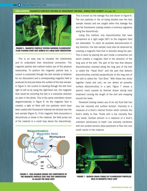
FIGURE 5 - MAGNETIC PARTICLE TESTING SHOWING FLUORESCENT<br />
FLUID FLOWING OVER TEST SAMPLE IN A HEAD SHOT ORIENTATION<br />
This is an easy way to visualize the relationship<br />
and to understand their directional connection. The<br />
magnetic particle test method makes use of this physical<br />
relationship. To perform the magnetic particle test, a<br />
current is conducted through the test sample (a fastener<br />
for our discussion) and a corresponding magnetic field is<br />
produced at and just below the surface of the test sample.<br />
In Figure 5, the current is traveling through the bolt from<br />
right to left so by using the right-hand rule, the magnetic<br />
field would be encircling the bolt in a clockwise direction<br />
as seen in the photo. This is the same orientation shown<br />
diagrammatically in Figure 6. As the magnetic field is<br />
created, a light oil filled with iron particles which have<br />
been coated with fluorescent material are drizzled over the<br />
test sample (Figure 5). If the magnetic field encounters a<br />
discontinuity or break in the material, the field jumps out<br />
of the material in a small loop above the discontinuity.<br />
This is known as the leakage flux and shown in Figure 6.<br />
The iron particles in the oil being drizzled over the test<br />
sample interact and are caught within this leakage flux<br />
and the fluorescent coating creates a luminous signature<br />
along the discontinuity.<br />
Using this method, only discontinuities that have<br />
component at a right angle (90°) to the magnetic field<br />
are detectable. To catch all possible discontinuities in<br />
any direction, the test sample must also be observed by<br />
creating a magnetic field that is directed along the part.<br />
This is done by placing the part inside a conductive coil<br />
which creates a magnetic field in the direction of the<br />
long axis of the bolt. The part of the test that detects<br />
discontinuities oriented along the long axis of the bolt<br />
is called the “Head Shot” and the part that detects<br />
discontinuities oriented perpendicular to the long axis of<br />
the bolt is called the “Coil Shot.” With these two shots<br />
together (head and coil), we can detect all possible<br />
surface discontinuities in a part. Figure 7 shows a<br />
quench crack caused by thermal stress during heat<br />
treatment running the length of the bolt and wrapping<br />
around the head.<br />
Penetrant testing makes use of an oily fluid that has<br />
very low viscosity and surface tension. Viscosity is a<br />
measure of a fluid’s internal friction which controls the<br />
fluid’s ability to flow. Fluids with a low viscosity flow<br />
very easily. Surface tension is a measure of a fluid’s<br />
cohesion (stickiness) to itself. Low viscosity combined<br />
with low surface tension allow penetrant to flow into very<br />
small cracks in the material.<br />
FIGURE 6 - THIS DIAGRAM SHOWS THE COMPONENTS OF<br />
THE MAGNETIC PARTICLE TEST THIS TEST ORIENTATION<br />
IS CALLED THE HEAD SHOT<br />
FIGURE 7 - QUENCH CRACK VISIBLE BY FLUORESCENT PARTICLES<br />
HELD IN MAGNETIC FIELD LOOP<br />
CONTINUED ON PAGE 172