

Rosemount TankMaster - Emerson Process Management
Rosemount TankMaster - Emerson Process Management
Rosemount TankMaster - Emerson Process Management

Create successful ePaper yourself
Turn your PDF publications into a flip-book with our unique Google optimized e-Paper software.
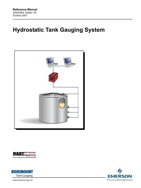
Reference Manual<br />
303033EN, Edition 1B<br />
October 2007<br />
Hydrostatic Tank Gauging System<br />
www.rosemount-tg.com
Reference Manual<br />
303033EN, Edition 1B<br />
October 2007<br />
www.rosemount-tg.com<br />
<strong>Rosemount</strong> <strong>TankMaster</strong><br />
Cover Photo: Cover_system_layout.eps<br />
NOTICE<br />
<strong>Rosemount</strong> <strong>TankMaster</strong><br />
Read this manual before working with the product. For personal and system safety, and for<br />
optimum product performance, make sure you thoroughly understand the contents before<br />
installing, using, or maintaining this product.<br />
For equipment service or support needs, contact your local <strong>Emerson</strong> <strong>Process</strong><br />
<strong>Management</strong>/<strong>Rosemount</strong> Tank Gauging representative.<br />
The contents, descriptions and specifications within this manual is subject to change<br />
without notice. <strong>Rosemount</strong> TankRadar AB accepts no responsibility for any errors that may<br />
appear in this manual.<br />
Spare Parts<br />
Any substitution of non-recognized spare parts may jeopardize safety. Repair, e.g.<br />
substitution of components etc, may also jeopardize safety and is under no circumstances<br />
allowed.<br />
<strong>Rosemount</strong> Tank Radar AB will not take any responsibility for faults, accidents, etc caused<br />
by non-recognized spare parts or any repair which is not made by<br />
<strong>Rosemount</strong> Tank Radar AB.<br />
Specific FCC Requirements (USA only)<br />
<strong>Rosemount</strong> TankRadar REX generates and uses radio frequency energy. If it is not installed<br />
and used properly, that is, in strict accordance with the manufacturer´s instructions, it may<br />
violate FCC regulations on radio frequency emission.<br />
<strong>Rosemount</strong> TankRadar REX has been FCC certified under test conditions which assume a<br />
metallic tank. Installation on a non-metallic tank is not certified, and is not allowed.<br />
The FCC certificate for <strong>Rosemount</strong> TankRadar REX requires that the tank is closed as far<br />
as emitted radio energy is concerned. Tanks with open manholes, external-floating-roof<br />
tanks without still pipes etc. are not covered by the certificate.
Reference Manual<br />
303033EN, Edition 1B<br />
October 2007<br />
SECTION 1<br />
Getting started<br />
SECTION 2<br />
System overview<br />
SECTION 3<br />
Installation<br />
SECTION 4<br />
Tank Inventory<br />
Configuration<br />
SECTION 5<br />
Alarm handling<br />
SECTION 6<br />
Viewing Tank Data<br />
www.rosemount-tg.com<br />
Table of Contents<br />
<strong>Rosemount</strong> Tank Master<br />
1.1 Introduction . . . . . . . . . . . . . . . . . . . . . . . . . . . . . . . . . . . . . . . . 1-1<br />
1.2 Definitions and abbreviations . . . . . . . . . . . . . . . . . . . . . . . . . . 1-1<br />
2.1 Introduction . . . . . . . . . . . . . . . . . . . . . . . . . . . . . . . . . . . . . . . . 2-1<br />
2.1.1 Components. . . . . . . . . . . . . . . . . . . . . . . . . . . . . . . . 2-2<br />
2.1.2 Communication . . . . . . . . . . . . . . . . . . . . . . . . . . . . . 2-2<br />
2.2 Function. . . . . . . . . . . . . . . . . . . . . . . . . . . . . . . . . . . . . . . . . . . 2-3<br />
3.1 Software configuration. . . . . . . . . . . . . . . . . . . . . . . . . . . . . . . . 3-1<br />
4.1 Tank HTG Calculations . . . . . . . . . . . . . . . . . . . . . . . . . . . . . . . 4-1<br />
4.2 Tank Capacity Setup . . . . . . . . . . . . . . . . . . . . . . . . . . . . . . . . . 4-3<br />
4.3 Volume Calculation Setup . . . . . . . . . . . . . . . . . . . . . . . . . . . . . 4-5<br />
5.1 Device alarms and tank alarms . . . . . . . . . . . . . . . . . . . . . . . . . 5-1<br />
5.2 Alarm configuration . . . . . . . . . . . . . . . . . . . . . . . . . . . . . . . . . . 5-1<br />
5.2.1 Set level alarm limits or sensor alarm<br />
limits for HTG-tanks . . . . . . . . . . . . . . . . . . . . . . . . . . 5-1<br />
5.2.2 Set volume alarm limits for a HTG-tank . . . . . . . . . . . 5-3<br />
6.1 Tank Inventory. . . . . . . . . . . . . . . . . . . . . . . . . . . . . . . . . . . . . . 6-1<br />
6.2 Reports . . . . . . . . . . . . . . . . . . . . . . . . . . . . . . . . . . . . . . . . . . . 6-2
<strong>Rosemount</strong> Tank Radar REX<br />
Reference Manual<br />
303033EN, Edition 1B<br />
October 2007<br />
TOC-2 Table of Contents
Reference Manual<br />
303033EN, Edition 1B<br />
October 2007<br />
Section 1 Getting Started<br />
www.rosemount-tg.com<br />
<strong>Rosemount</strong> Tank Master<br />
1.1 Introduction . . . . . . . . . . . . . . . . . . . . . . . . . . . . . . . . page 1-1<br />
1.2 Definitions and abbreviations . . . . . . . . . . . . . . . . . page 1-1<br />
1.1 INTRODUCTION Hydrostatic Tank Gauging (HTG) is a pressure measuring method used<br />
mostly in the refining, petrochemical and chemical industries. The method is<br />
simple: pressure readouts from transmitters in the tank are used to calculate<br />
the weight of the product.<br />
1.2 DEFINITIONS AND<br />
ABBREVIATIONS<br />
This document describes the system overview, installation and operation of<br />
the <strong>TankMaster</strong> HTG System developed by <strong>Rosemount</strong> Tank Gauging.<br />
The HTG System is an extension to the already existing <strong>TankMaster</strong> System.<br />
For instructions how to install, configure and use the <strong>TankMaster</strong> system, see<br />
<strong>Rosemount</strong> <strong>TankMaster</strong> WinSetup User’s Guide [Ref. no. 303027 EN] and<br />
<strong>Rosemount</strong> <strong>TankMaster</strong> WinOpi User’s Guide [Ref. no. 303028 EN].<br />
Abbreviation Explanation<br />
HTG Hydrostatic Tank Gauging<br />
FCU Field Communication Unit<br />
GOV Gross Observed Volume<br />
GSV Gross Standard Volume<br />
LAN Local Area Network<br />
DS4 Director Series 4<br />
NSV Net Standard Volume<br />
RTG Radar Tank Gauge<br />
TCP/IP Transmission Control Protocol/Internet Protocol<br />
TCT Tank Capacity Table<br />
TOV Total Observed Volume<br />
VCF Volume Correction Factor
<strong>Rosemount</strong> Tank Master<br />
Reference Manual<br />
303033EN, Edition 1B<br />
October 2007<br />
1-2 Section 1. Getting Started
Reference Manual<br />
303033EN, Edition 1B<br />
October 2007<br />
Section 2 System Overview<br />
www.rosemount-tg.com<br />
<strong>Rosemount</strong> Tank Master<br />
2.1 Introduction . . . . . . . . . . . . . . . . . . . . . . . . . . . . . . . . page 2-1<br />
2.2 Function . . . . . . . . . . . . . . . . . . . . . . . . . . . . . . . . . . page 2-3<br />
2.1 INTRODUCTION The <strong>TankMaster</strong> HTG system is an intelligent direct mass measuring system.<br />
It takes advantage of the high precision pressure transmitters installed at<br />
different levels in the tank. HTG uses product hydrostatic pressure<br />
measurements to derive both the specific gravity and liquid level.<br />
Figure 2-1. System Layout<br />
<strong>TankMaster</strong> PC<br />
for data communication,<br />
calculations, displaying and<br />
reporting<br />
Modem<br />
RS-485<br />
LAN<br />
RS-232<br />
Two alternative<br />
interfaces, RS-232 or<br />
RS-485 with modem<br />
Host<br />
Director Series<br />
(DS4)<br />
Modbus Communication<br />
Hart Communication<br />
P3<br />
P2<br />
T<br />
P1
<strong>Rosemount</strong> Tank Master<br />
2.1.1 Components DS4<br />
2.1.2 Communication <strong>TankMaster</strong> to DS4<br />
Reference Manual<br />
303033EN, Edition 1B<br />
October 2007<br />
The Director Series 4 (DS4) is a gateway for enabling operational data to be<br />
acquired, transformed and utilized through full TCP/IP communication. The<br />
DS4 polls the transmitters for Primary Values (PV) and Secondary Values<br />
(SV) and sends information to the <strong>TankMaster</strong> network.<br />
The DS4 is factory configured.<br />
Pressure and Temperature Transmitters<br />
<strong>Rosemount</strong> pressure and temperature transmitters support the DS4 with<br />
measurement data. Different types and numbers of transmitters are used<br />
depending on tank configuration. For example, a tank with vapor pressure<br />
requires three transmitters for online measurement. Two transmitters<br />
measuring the liquid pressure and one at the top measuring the vapor<br />
pressure.<br />
All transmitter configuration is done using 275/375 handheld communicator or<br />
AMS suite software.<br />
WinOpi<br />
The program supports data display of mass data as well as data entry. In<br />
order to display special HTG windows and HTG values, a special hardware<br />
key with HTG option is needed.<br />
TankServer<br />
The TankServer calculates the mass value and other variables and handles<br />
the alarms. It also polls the DS4 for the PVs and SVs. In order for the<br />
TankServer to calculate HTG values, a special hardware key with the HTG<br />
option is needed.<br />
Electrical interface<br />
The electrical interface uses RS-232 or RS-485 standard interface. A modem<br />
is needed for converting the RS-485 to RS-232.<br />
<strong>TankMaster</strong> communicates via Modbus protocol to the DS4 devices. It polls<br />
the registers where the DS4 has cashed PV and SV from the transmitters.<br />
DS4 to HART transmitters<br />
The DS4 polls PV and SV from the transmitters using HART protocol.<br />
OPC compatibility<br />
<strong>TankMaster</strong> uses OPC Data Access 2.0, an open industry standard. With the<br />
OPC standard it is easy to import information from other OPC clients.<br />
2-2 Section 2. System Overview
Reference Manual<br />
303033EN, Edition 1B<br />
October 2007<br />
Section 2. System Overview<br />
<strong>Rosemount</strong> Tank Master<br />
2.2 FUNCTION HTG uses product hydrostatic pressure measurements to derive both specific<br />
gravity and liquid level. A typical HTG system uses three pressure<br />
transmitters: one near the bottom of the tank, another above the first, and a<br />
third at the top.<br />
Figure 2-2. HTG tank setup<br />
Figure 2-3. Block diagram HTG<br />
calculation<br />
Comparison of the pressure readouts from the two submerged transmitters<br />
are used to calculate the specific gravity of the liquid thus generating mass<br />
and density. The liquid level can be determined by comparing readouts from<br />
the transmitter above the liquid level (which measures the vapor pressure in<br />
the tank) and the transmitter at the bottom.<br />
TCT PRESSURE TRANSMITTERS TEMPERATURE<br />
MASS(WEIGHT)<br />
LEVEL<br />
DENSITY<br />
Vapor pressure<br />
Liquid pressure<br />
Temperature<br />
P1 Liquid pressure<br />
As a complement the temperature measurement is needed to get the<br />
standard volume.<br />
P3<br />
P2<br />
T<br />
STANDARD VOLUME<br />
2-3
<strong>Rosemount</strong> Tank Master<br />
Reference Manual<br />
303033EN, Edition 1B<br />
October 2007<br />
2-4 Section 2. System Overview
Reference Manual<br />
303033EN, Edition 1B<br />
October 2007<br />
Section 3 Installation<br />
3.1 SOFTWARE<br />
CONFIGURATION<br />
Figure 3-1. Select Setup<br />
www.rosemount-tg.com<br />
<strong>Rosemount</strong> Tank Master<br />
3.1 Software configuration . . . . . . . . . . . . . . . . . . . . . . page 3-1<br />
For a complete installation do the following:<br />
1. “Configure Preferences” on page 3-1.<br />
2. “Configure the ModbusMaster protocol” on page 3-3.<br />
3. “Install Device DS4” on page 3-5.<br />
4. “Tank installation” on page 3-7.<br />
Before doing the configuration for the HTG system perform the WinSetup<br />
installation, see <strong>Rosemount</strong> <strong>TankMaster</strong> WinSetup User’s Guide.<br />
Step 1 Configure Preferences<br />
In this step important parameters for units, volume correction, gravity, air<br />
density and Tank Capacity Table (TCT) are set.<br />
NOTE!<br />
It is important to set parameters in the Preferences before continuing with the<br />
device and tank installation. The installed tanks will otherwise display<br />
incorrect values.<br />
1. Select the desired server (for example “This Workstation”) in the<br />
<strong>TankMaster</strong> WinSetup workspace.<br />
2. Right click and select Setup.
<strong>Rosemount</strong> Tank Master<br />
Figure 3-2. Preferences window<br />
in WinSetup<br />
Reference Manual<br />
303033EN, Edition 1B<br />
October 2007<br />
3. Choose System Units and remaining parameters as correct as possible.<br />
Click OK.<br />
These parameters are important when setting up tanks and performing<br />
the calculations.<br />
3-2 Section 3. Installation
Reference Manual<br />
303033EN, Edition 1B<br />
October 2007<br />
Figure 3-3. ModbusMaster<br />
protocol<br />
Figure 3-4. Modbus protocol<br />
properties<br />
Section 3. Installation<br />
Step 2. Configure the ModbusMaster protocol<br />
<strong>Rosemount</strong> Tank Master<br />
The ModbusMaster protocol must be configured in order for the network<br />
connection to work. Do the following to enable the ModbusMaster protocol in<br />
WinSetup:<br />
1. In the WinSetup workspace open the Protocols folder.<br />
2. Select the protocol icon that corresponds to the protocol to be<br />
configured.<br />
3. Click the right mouse button and select Properties.<br />
4. Select the desired channel.<br />
5. Click the Properties button.<br />
3-3
<strong>Rosemount</strong> Tank Master<br />
Figure 3-5. Protocol channel<br />
configuration<br />
Reference Manual<br />
303033EN, Edition 1B<br />
October 2007<br />
6. Select the Communication tab and configure the communication<br />
parameters: Baud Rate: 19200, Modem: RS-232, Stop bits: 1 and Parity:<br />
None. Make sure that the Enable Channel check box is selected.<br />
Check that Port is set to the COM port that the DS4 is connected to.<br />
7. Click OK. The ModbusMaster protocol configuration is now finished.<br />
3-4 Section 3. Installation
Reference Manual<br />
303033EN, Edition 1B<br />
October 2007<br />
Figure 3-6. Select device<br />
Figure 3-7. Establish<br />
communication<br />
Section 3. Installation<br />
Step 3. Install Device DS4<br />
<strong>Rosemount</strong> Tank Master<br />
<strong>TankMaster</strong> does not support the HART protocol. The HTG system uses the<br />
DS4 for transforming the HART protocol to the Modbus protocol. In WinSetup<br />
the DS4 must be installed as a new device before a tank can be installed.<br />
1. Start the Device Installation Wizard, see Chapter 3.7 in <strong>Rosemount</strong><br />
<strong>TankMaster</strong> WinSetup User’s Guide. Click OK if the following message<br />
appears: “If your TankRadar system configuration has FCU you must<br />
install it first ...”<br />
2. Choose device type - DS4. Specify a name for the device in the<br />
corresponding Tag input field. In this installation example the name is<br />
DS4-1 but any name can be specified. If you want to install the DS4<br />
before the actual device is connected to the field bus, select the Install<br />
Offline check box.<br />
3. Click the Next button.<br />
3-5
<strong>Rosemount</strong> Tank Master<br />
Figure 3-8. Channel<br />
Configuration window<br />
Figure 3-9. The installed DS4<br />
appears in the WinSetup<br />
Workspace.<br />
Reference Manual<br />
303033EN, Edition 1B<br />
October 2007<br />
4. Check that the Communication Channel and Modbus Address are<br />
correct and click the Verify Communication button to make sure that<br />
communication is established.<br />
5. Click Next. The communication will be tested again. Click OK in the<br />
dialog box.<br />
6. Select HBI Port and Channel. There are two HBI Ports with two<br />
channels on each port. Check that all channels have been configured<br />
before moving on.<br />
7. Click the Get Value Units button. For each HART Poll Address select<br />
Device Type and type a Tag name. Check that the value units are<br />
correct.<br />
8. If Secondary Value is used unmark the PV Only check box.<br />
9. Click the Next button.<br />
10. Read summary and then click the Finish button.<br />
3-6 Section 3. Installation
Reference Manual<br />
303033EN, Edition 1B<br />
October 2007<br />
Figure 3-10. Install tank in<br />
WinSetup workspace<br />
Figure 3-11. Tank HTG<br />
configuration<br />
Section 3. Installation<br />
Step 4. Tank installation<br />
<strong>Rosemount</strong> Tank Master<br />
Continue with tank installation. The tank type will be selected by the user as a<br />
HTG-tank (three choices).<br />
1. Start the Tank Installation Wizard, see Chapter 3.5 in <strong>Rosemount</strong><br />
<strong>TankMaster</strong> WinSetup User’s Guide.<br />
2. Choose one of the three optional types of HTG tanks: HTG fixed roof,<br />
HTG floating roof or HTG floating blanket. Also enter appropriate<br />
Tag-name. Click Next.<br />
3. Select channels to associate with the tank as input for Liquid Pressure,<br />
Vapor Pressure and Temperature. Check the units for each device before<br />
clicking Next.<br />
3-7
<strong>Rosemount</strong> Tank Master<br />
Figure 3-12. The installed<br />
channels appear in the<br />
WinSetup workspace after the<br />
tank installation is finished.<br />
4. Click Finish and view the tank in the WinSetup workspace.<br />
Reference Manual<br />
303033EN, Edition 1B<br />
October 2007<br />
3-8 Section 3. Installation
Reference Manual<br />
303033EN, Edition 1B<br />
October 2007<br />
Section 4 Tank Inventory Configuration<br />
4.1 TANK HTG<br />
CALCULATIONS<br />
Figure 4-1. WinSetup<br />
Workspace<br />
www.rosemount-tg.com<br />
<strong>Rosemount</strong> Tank Master<br />
4.1 Tank HTG Calculations . . . . . . . . . . . . . . . . . . . . . . page 4-1<br />
4.2 Tank Capacity Setup . . . . . . . . . . . . . . . . . . . . . . . . . page 4-3<br />
4.3 Volume Calculation Setup . . . . . . . . . . . . . . . . . . . . page 4-5<br />
Position of the pressure sensors are set in the Tank HTG Calculations window<br />
that can be found in WinSetup.<br />
1. Select the HTG-tank in WinSetup Workspace window.<br />
2. Right click and select the HTG Tank Setup option.
<strong>Rosemount</strong> Tank Master<br />
Figure 4-2. Tank HTG<br />
Calculations Setup<br />
Reference Manual<br />
303033EN, Edition 1B<br />
October 2007<br />
3. Type the sensor positions for Vapor Pressure and Liquid Pressure. It is<br />
important that these figures are given with high accuracy. Enter the HTG<br />
Reference Point in the Ho Distance field. The Ho Distance parameter is<br />
equal to zero if the Datum Plate is used as HTG Reference Point,<br />
otherwise the Ho Distance is equal to the distance between the HTG<br />
Reference Point and the Datum Plate.<br />
The Thresholds settings can be used to avoid HTG calculations in a<br />
measurement range where the pressure sensor accuracy is low. The<br />
P1-P2 threshold sets the lower limit for how close to the P1 sensor HTG<br />
calculations are performed. The P2-P3 threshold sets a similar limit for<br />
the P2 sensor.<br />
Installation Temperature is the temperature inside the tank at the time<br />
when the sensor positions were measured.<br />
NOTE!<br />
It is important to type the positions with three decimals.<br />
The positions should always be measured to the centre of the sensor<br />
pressure membrane.<br />
The HTG reference point can have the same position as the Datum Plate.<br />
4. Click OK.<br />
4-2 Section 4. Tank Inventory Configuration
Reference Manual<br />
303033EN, Edition 1B<br />
October 2007<br />
4.2 TANK CAPACITY<br />
SETUP<br />
Figure 4-3. Tank Capacity in<br />
WinSetup Workspace<br />
Figure 4-4. Tank Capacity Table<br />
Section 4. Tank Inventory Configuration<br />
<strong>Rosemount</strong> Tank Master<br />
The tank geometry is defined in a Strapping Table, also called Tank Capacity<br />
Table, which converts the product level to the corresponding volume.<br />
To create a Tank Capacity Table do the following:<br />
1. Select the HTG-tank in WinSetup Workspace window.<br />
2. Right click and select the Tank Capacity option.<br />
4-3
<strong>Rosemount</strong> Tank Master<br />
3. Enter the corresponding level and volume values.<br />
Reference Manual<br />
303033EN, Edition 1B<br />
October 2007<br />
NOTE!<br />
Sump Volume is the volume below the Zero Level, see <strong>Rosemount</strong><br />
<strong>TankMaster</strong> WinOpi User’s Guide. Base Temp is the temperature in the tank<br />
when the strapping table was created.<br />
4. Click OK.<br />
4-4 Section 4. Tank Inventory Configuration
Reference Manual<br />
303033EN, Edition 1B<br />
October 2007<br />
4.3 VOLUME<br />
CALCULATION<br />
SETUP<br />
Figure 4-5. WinSetup<br />
Workspace<br />
Figure 4-6. Tank Volume<br />
Calculation Setup window<br />
Section 4. Tank Inventory Configuration<br />
<strong>Rosemount</strong> Tank Master<br />
To configure the tank for volume calculations do the following:<br />
1. Select the HTG-tank in the WinSetup Workspace window.<br />
2. Right click and select Tank Volume Calculation option.<br />
4-5
<strong>Rosemount</strong> Tank Master<br />
Reference Manual<br />
303033EN, Edition 1B<br />
October 2007<br />
3. Select desired Product. Inventory calculations are based on various<br />
parameters which are specified in the Product Table. The Product Table<br />
can be extended with new products when needed. See <strong>Rosemount</strong><br />
<strong>TankMaster</strong> WinOpi User’s Guide for a description of how to edit the<br />
Product Table.<br />
NOTE!<br />
If a vapor product is specified then type the vapor density in the Vapor Density<br />
Setup.<br />
4-6 Section 4. Tank Inventory Configuration
Reference Manual<br />
303033EN, Edition 1B<br />
October 2007<br />
Section 5 Alarm handling<br />
5.1 DEVICE ALARMS<br />
AND TANK<br />
ALARMS<br />
www.rosemount-tg.com<br />
<strong>Rosemount</strong> Tank Master<br />
5.1 Device alarms and tank alarms . . . . . . . . . . . . . . . . page 5-1<br />
5.2 Alarm configuration . . . . . . . . . . . . . . . . . . . . . . . . . page 5-2<br />
The possible alarms in the HTG system are Hi, Lo or CFail. CFail is a<br />
communication failure, and means that <strong>TankMaster</strong> is not able to<br />
communicate with the device at the moment. Hi and Lo means that the live<br />
values from the transmitters or the calculated values from <strong>TankMaster</strong> are too<br />
high or too low compared with a user defined limit. See “Set level alarm limits<br />
or sensor alarm limits for HTG-tanks” on page 5-2 for how to set these limits.<br />
The values received from the different field devices are continuously checked<br />
against the alarm limits. If a value has passed an alarm limit, it will be<br />
activated after a delay time given by the Delay Time option.<br />
The alarm status is shown with a flashing bright red color in the Alarm<br />
Summary window. When the operator has accepted the alarm the status is<br />
shown in dark red color.<br />
In order to disable an alarm the parameter that caused the alarm must pass<br />
below the alarm limit and an extra amount specified by the Hysteresis value.<br />
When these conditions are fulfilled the alarm reset is delayed an amount of<br />
time given by the Delay Time.
<strong>Rosemount</strong> Tank Master<br />
5.2 ALARM<br />
CONFIGURATION<br />
5.2.1 Set level alarm<br />
limits or sensor<br />
alarm limits for<br />
HTG-tanks<br />
Figure 5-1. Select Alarm Limits<br />
Figure 5-2. Alarm Limits. Note<br />
the sensor values for the<br />
pressure sensors.<br />
Reference Manual<br />
303033EN, Edition 1B<br />
October 2007<br />
The following section describes how to set alarm limits for HTG-tanks. This is<br />
similar to the alarm handling described in the <strong>Rosemount</strong> <strong>TankMaster</strong> WinOpi<br />
User’s Guide.<br />
To set or change the alarm limits for a HTG-tank do the following:<br />
1. Select the HTG-tank in the WinOpi Workspace window.<br />
2. Right click the tank and select the Alarm Limits option.<br />
3. Set desired Alarm Limits. Alarm Limits for Level values refer to the<br />
calculated values based on input from the various pressure sensors.<br />
Alarm Limits for Sensors refer to the actual measurement values that are<br />
presented by the pressure sensors. Click the OK button.<br />
For explanations of Leak and Hysteresis see Chapter 5 in <strong>Rosemount</strong><br />
<strong>TankMaster</strong> WinOpi User’s Guide.<br />
5-2 Section 5. Alarm handling
Reference Manual<br />
303033EN, Edition 1B<br />
October 2007<br />
5.2.2 Set volume alarm<br />
limits for a<br />
HTG-tank<br />
Figure 5-3. Select Volume Tank<br />
Limits<br />
Figure 5-4. Volume Alarm Limits<br />
Section 5. Alarm handling<br />
1. Select the HTG-tank in the WinOpi Workspace window.<br />
<strong>Rosemount</strong> Tank Master<br />
2. Right click the tank and select the Volume Alarm Limits option.<br />
5-3
<strong>Rosemount</strong> Tank Master<br />
Reference Manual<br />
303033EN, Edition 1B<br />
October 2007<br />
3. Set the desired Alarm Limits for Net Standard Volume (See the<br />
<strong>Rosemount</strong> <strong>TankMaster</strong> WinOpi User’s Guide for a description of<br />
standard volumes). The Flow Rate alarm can be set to indicate an<br />
uncontrolled flow in or out of the tank.<br />
4. Click the OK button.<br />
5-4 Section 5. Alarm handling
Reference Manual<br />
303033EN, Edition 1B<br />
October 2007<br />
Section 6 Viewing Tank Data<br />
www.rosemount-tg.com<br />
<strong>Rosemount</strong> Tank Master<br />
6.1 Tank Inventory . . . . . . . . . . . . . . . . . . . . . . . . . . . . . page 6-1<br />
6.2 Reports . . . . . . . . . . . . . . . . . . . . . . . . . . . . . . . . . . . page 6-2<br />
6.1 TANK INVENTORY Summary of levels, volumes, weights, product, temperature and pressure can<br />
be viewed in the Tank Inventory window.<br />
Figure 6-1. The WinOpi<br />
Workspace.<br />
1. Select the tank in the WinOpi Workspace window.<br />
2. Right click the tank and select View Tank > Inventory.
<strong>Rosemount</strong> Tank Master<br />
Figure 6-2. The Tank Inventory<br />
window.<br />
Reference Manual<br />
303033EN, Edition 1B<br />
October 2007<br />
NOTE!<br />
Values highlighted with yellow background are manually typed.<br />
For Weight In Air (WIA) the air pressure is taken into consideration when<br />
calculating the product weight.<br />
The Weight in Vacuum (WIV) is the product weight in vacuum i.e. the mass of<br />
the product.<br />
6.2 REPORTS Two standard report types are available: Log report and Mass balance<br />
report. See <strong>Rosemount</strong> <strong>TankMaster</strong> WinOpi User’s Guide for further<br />
information.<br />
Reports can be published automatically at a predefined schedule. They can<br />
also be distributed by an operator at any moment. Reports can be printed,<br />
emailed or saved to file.<br />
6-2 Section 6. Viewing Tank Data
Reference Manual<br />
303033EN, Edition 1B<br />
October 2007<br />
<strong>TankMaster</strong> is a trademark of <strong>Rosemount</strong> Tank Radar AB.<br />
Modbus is a registered trademark of Modicon.<br />
<strong>Rosemount</strong> and the <strong>Rosemount</strong> logotype are registered trademarks of <strong>Rosemount</strong> Inc.<br />
HART is a registered trademark of the HART Communication Foundation.<br />
All other marks are the property of their respective owners.<br />
<strong>Emerson</strong> <strong>Process</strong> <strong>Management</strong><br />
<strong>Rosemount</strong> Tank Gauging<br />
Box 130 45<br />
SE-402 51 Göteborg<br />
SWEDEN<br />
Tel (International): +46 31 337 00 00<br />
Fax (International): +46 31 25 30 22<br />
E-mail: sales.srt@emersonprocess.com<br />
www.rosemount-tg.com<br />
© 2007 <strong>Rosemount</strong> Tank Radar AB. All rights reserved.<br />
<strong>Rosemount</strong> <strong>TankMaster</strong>


