FOXBOX Tx/Rx VGA, VGA/YUV, DVI, and - Extron Electronics
FOXBOX Tx/Rx VGA, VGA/YUV, DVI, and - Extron Electronics
FOXBOX Tx/Rx VGA, VGA/YUV, DVI, and - Extron Electronics

You also want an ePaper? Increase the reach of your titles
YUMPU automatically turns print PDFs into web optimized ePapers that Google loves.
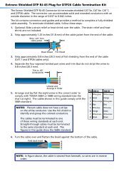
d RS-232 Over Fiber port — If you want the <strong>FOXBOX</strong> to pass serial<br />
comm<strong>and</strong> signals to the receiver, for serial control of a projector for example,<br />
RS-232<br />
OVER FIBER ALARM<br />
connect the host device to the transmitter via the first three leftmost poles<br />
(<strong>Tx</strong>, <strong>Rx</strong>, <strong>and</strong> _) of this 5-pole captive screw connector (see “RS-232<br />
connections“ on page 15 to wire this connector).<br />
<strong>Tx</strong> <strong>Rx</strong> 1 2<br />
NOTES: • If you connect only one fiber optic cable (item f, below), or you<br />
configure the receiver for daisy-chaining, you will not receive reports<br />
from the controlled device. To receive responses from the controlled<br />
device, you must install two fiber optic cables <strong>and</strong> leave the <strong>FOXBOX</strong><br />
receiver in normal configuration (Mode DIP switch 1 down on the receiver).<br />
• The <strong>FOXBOX</strong> can pass RS-232 comm<strong>and</strong>s <strong>and</strong> responses at rates up to<br />
115200 baud.<br />
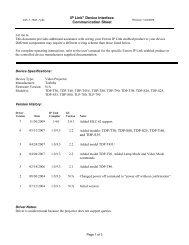
e Alarm outputs port — For remote monitoring of the status of fiber optic<br />
link 2, connect a locally-constructed or furnished monitoring device to the<br />
RS-232<br />
OVER FIBER ALARM<br />
transmitter via the two rightmost poles (1 <strong>and</strong> 2) of this 5-pole captive screw<br />
connector. When the transmitter does not detect a light link on fiber cable<br />
<strong>Tx</strong> <strong>Rx</strong> 1 2<br />
<strong>Rx</strong> (optional), pin 1 <strong>and</strong> pin 2 of this port are shorted together (see “Alarm outputs<br />
connection“ on page 15 to wire this connector).<br />
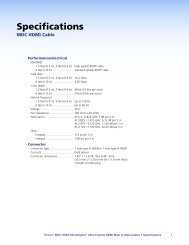
f Fiber optic connectors <strong>and</strong> LEDs —<br />
WARNING: These units output continuous invisible light, which may be harmful to<br />
the eyes; use with caution. For additional safety, plug the attached dust<br />
caps into the optical transceivers when the fiber cable is unplugged.<br />
NOTES: • Ensure that you use the proper fiber cable for your transmitter/receiver<br />
pair. Typically, singlemode fiber has a yellow jacket <strong>and</strong> multimode cable<br />
has an orange or aqua jacket.<br />
• Only one fiber optic cable, transmitter <strong>Tx</strong> to receiver <strong>Rx</strong>, is required for<br />
video, audio, <strong>and</strong> serial comm<strong>and</strong> transmission. But, if you connect only<br />
one fiber optic cable, or if your transmitter is configured to daisy-chain<br />
the optical signal, system functionality is reduced. You will not receive<br />
RS-232 reports from the controlled device, <strong>and</strong> some FOX Extender<br />
Control Program functions <strong>and</strong> RS-232 comm<strong>and</strong>s will not work. To<br />
receive responses from the controlled device <strong>and</strong> for full functionality, you<br />
need to install both fiber optic cables <strong>and</strong> leave the <strong>FOXBOX</strong> receiver in<br />
normal configuration (Mode DIP switch 1 down on the receiver).<br />
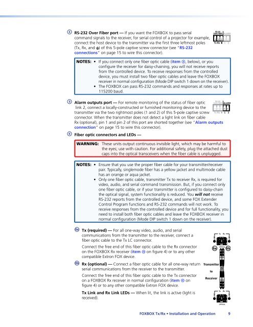
ä <strong>Tx</strong> (required) — For all one-way video, audio, <strong>and</strong> serial<br />
communications from the transmitter to the receiver, connect a<br />
fiber optic cable to the <strong>Tx</strong> LC connector.<br />
Connect the free end of this fiber optic cable to the <strong>Rx</strong> connector<br />
on the <strong>FOXBOX</strong> <strong>Rx</strong> receiver (item o on figure 4) or to any other<br />
compatible <strong>Extron</strong> FOX device.<br />
ã <strong>Rx</strong> (optional) — Connect a fiber optic cable for all one-way return<br />
serial communications from the receiver to the transmitter.<br />
Connect the free end of this fiber optic cable to the <strong>Tx</strong> connector<br />
on a <strong>FOXBOX</strong> <strong>Rx</strong> receiver in normal configuration (item o on<br />
figure 4) or to any other compatible <strong>Extron</strong> FOX device.<br />
<strong>Tx</strong> Link <strong>and</strong> <strong>Rx</strong> Link LEDs — When lit, the link is active (light is<br />
received).<br />
Transmitter<br />
to<br />
LINK<br />
Receiver<br />
LINK<br />
<strong>Tx</strong><br />
OPTICAL<br />
6a 6b<br />
<strong>Tx</strong><br />
<strong>Rx</strong><br />
<strong>Rx</strong><br />
OPTICAL<br />
<strong>FOXBOX</strong> <strong>Tx</strong>/<strong>Rx</strong> • Installation <strong>and</strong> Operation 9<br />
LINK<br />
LINK