FOXBOX Tx/Rx VGA, VGA/YUV, DVI, and - Extron Electronics
FOXBOX Tx/Rx VGA, VGA/YUV, DVI, and - Extron Electronics
FOXBOX Tx/Rx VGA, VGA/YUV, DVI, and - Extron Electronics

Create successful ePaper yourself
Turn your PDF publications into a flip-book with our unique Google optimized e-Paper software.
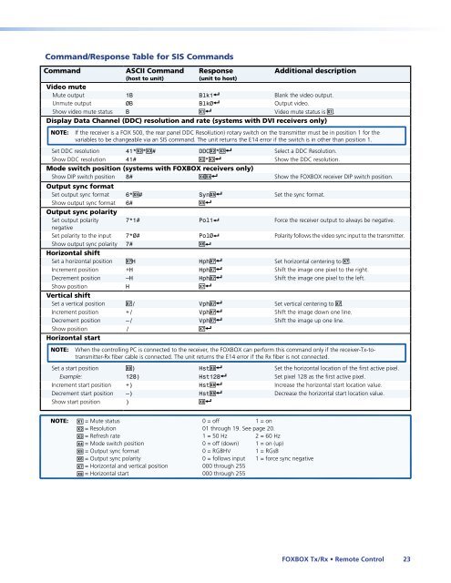
Comm<strong>and</strong>/Response Table for SIS Comm<strong>and</strong>s<br />
Comm<strong>and</strong> ASCII Comm<strong>and</strong><br />
(host to unit)<br />
Response<br />
(unit to host)<br />
Additional description<br />
Video mute<br />
Mute output 1B Blk1] Blank the video output.<br />
Unmute output 0B Blk0] Output video.<br />
Show video mute status B X!] Video mute status is X!.<br />
Display Data Channel (DDC) resolution <strong>and</strong> rate (systems with <strong>DVI</strong> receivers only)<br />
NOTE: If the receiver is a FOX 500, the rear panel DDC Resol(ution) rotary switch on the transmitter must be in position 1 for the<br />
variables to be changeable via an SIS comm<strong>and</strong>. The unit returns the E14 error if the switch is in other than position 1.<br />
Set DDC resolution 41*X@*X## DDCX@*X#] Select a DDC Resolution.<br />
Show DDC resolution 41# X@*X#] Show the DDC resolution.<br />
Mode switch position (systems with <strong>FOXBOX</strong> receivers only)<br />
Show DIP switch position 8# X$X$] Show the <strong>FOXBOX</strong> receiver DIP switch position.<br />
Output sync format<br />
Set output sync format 6*X%# SynX%] Set the sync format.<br />
Show output sync format<br />
Output sync polarity<br />
6# X%]<br />
Set output polarity<br />
negative<br />
7*1# Pol1] Force the receiver output to always be negative.<br />
Set polarity to the input 7*0# Pol0] Polarity follows the video sync input to the transmitter.<br />
Show output sync polarity<br />
Horizontal shift<br />
7# X^]<br />
Set a horizontal position X&H HphX&] Set horizontal centering to X&.<br />
Increment position +H HphX&] Shift the image one pixel to the right.<br />
Decrement position –H HphX&] Shift the image one pixel to the left.<br />
Show position<br />
Vertical shift<br />
H X&]<br />
Set a vertical position X&/ VphX&] Set vertical centering to X&.<br />
Increment position +/ VphX&] Shift the image down one line.<br />
Decrement position –/ VphX&] Shift the image up one line.<br />
Show position<br />
Horizontal start<br />
/ X&]<br />
NOTE: When the controlling PC is connected to the receiver, the <strong>FOXBOX</strong> can perform this comm<strong>and</strong> only if the receiver-<strong>Tx</strong>-totransmitter-<strong>Rx</strong><br />
fiber cable is connected. The unit returns the E14 error if the <strong>Rx</strong> fiber is not connected.<br />
Set a start position X*) HstX*] Set the horizontal location of the first active pixel.<br />
Example: 128) Hst128] Set pixel 128 as the first active pixel.<br />
Increment start position +) HstX*] Increase the horizontal start location value.<br />
Decrement start position –) HstX*] Decrease the horizontal start location value.<br />
Show start position ) X*]<br />
NOTE: X! = Mute status 0 = off 1 = on<br />
X@ = Resolution 01 through 19. See page 20.<br />
X# = Refresh rate 1 = 50 Hz 2 = 60 Hz<br />
X$ = Mode switch position 0 = off (down) 1 = on (up)<br />
X% = Output sync format 0 = RGBHV 1 = RGsB<br />
X^ = Output sync polarity 0 = follows input 1 = force sync negative<br />
X& = Horizontal <strong>and</strong> vertical position 000 through 255<br />
X* = Horizontal start 000 through 255<br />
<strong>FOXBOX</strong> <strong>Tx</strong>/<strong>Rx</strong> • Remote Control 23