


You also want an ePaper? Increase the reach of your titles
YUMPU automatically turns print PDFs into web optimized ePapers that Google loves.
UPWIND<br />
same as in state 1, changes in geometry of the inflow occur. On the one hand the resulting<br />
inflow shows a lower magnitude which is negligible over a wide range of operational conditions,<br />
especially in the outer part of the rotor blades. On the other hand the inflow angle is decreased<br />
resulting in a decreased angle of attack. Decreasing the angle of attack results in changes of<br />
the aerodynamic coefficients as shown in Figure 2.10. In normal operation conditions a<br />
decreased angle of attack correlates with decreased lift coefficients and therefore with<br />
decreased lift forces. The decreased inflow angle tends to increase the sectional thrust force as<br />
a portion of the lift force, but the influence of the decreased sectional lift force is generally larger<br />
due to relatively small inflow angles. Of course this is only valid for the outer part of the blades,<br />
but the influence from the inner parts of the blades is much smaller due to the much smaller<br />
inflow velocity c. This reduction of the total thrust force Ft can be considered as an additional<br />
force superimposed to the reference thrust force (from state 1) acting against the direction of the<br />
tower top movement and therefore having a damping effect.<br />
It should also be noted that the circumferential (= tangential) force dFc decreases due to the<br />
change in the lift coefficient resulting in a lower overall torque and therefore in a lower power<br />
output.<br />
In state 3 the RNA shows the maximum downwind deflection but a zero velocity from the<br />
support structure movement. The instantaneous aerodynamic inflow conditions and forces<br />
correspond to those given in state 1 as shown in Figure 2.9. Differences in the deformed<br />
configurations of state 1 and state 3 due to the different orientation of the rotor plane with<br />
respect to the undeflected rotor plane are neglected.<br />
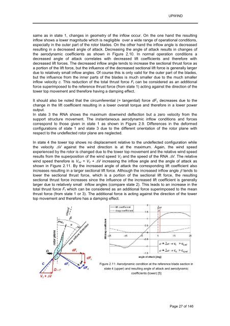
In state 4 the tower top shows no displacement relative to the undeflected configuration while<br />
the velocity �V against the wind direction is at the maximum. Again, the wind speed<br />
experienced by the rotor is changed due to the tower top movement and the relative wind speed<br />
results from the superposition of the wind speed V2 and the speed of the RNA �V. The relative<br />
wind speed therefore is Vrel = V2 + �V increasing the inflow angle and the angle of attack as<br />
shown in Figure 2.11. By the increased angle of attack the corresponding lift coefficient also<br />
increases resulting in a larger sectional lift force. Although the increased inflow angle � tends to<br />
lower the sectional thrust force, which is a portion of the sectional lift force, the resulting<br />
sectional thrust force increases since the influence of the increased lift coefficient is generally<br />
larger due to relatively small inflow angles (compare state 2). This leads to an increase in the<br />
total thrust force Ft which can be considered as an additional force superimposed to the mean<br />
thrust force (from state 1 or 3). The additional force is acting against the direction of the tower<br />
top movement and therefore has a damping effect.<br />
Figure 2.11: Aerodynamic condition at the reference blade section in<br />
state 4 (upper) and resulting angle of attack and aerodynamic<br />
coefficients (lower) [5]<br />
Page 27 of 146


