


Create successful ePaper yourself
Turn your PDF publications into a flip-book with our unique Google optimized e-Paper software.
UPWIND<br />
Another fact is that the dynamically critical and costly transition piece, as for jacket-tubular tower<br />
configurations, can be saved for truss-type support structures. Therefore the transition piece is<br />
moved to the connection between truss tower top and nacelle, which can also be difficult to<br />
design but in general lighter due to the lower bending moments from the aerodynamic loading<br />
from the rotor. Besides, the truss tower offers a geometrical flexibility. They can be designed as<br />
three leg towers but also as four leg solution. They can have different types of bracings, for<br />
example x-braces or z-braces.<br />
The complex structure of a truss tower also imposes much higher cost for manufacturing and<br />
maintenance, as the number of welds is increased significantly as well as the amount of joints to<br />
maintain and to secure against corrosion. The transparent tower cannot be used anymore for<br />
storage of power electronics or spare parts like heavy converters, as done for some offshore<br />
turbines in order to reduce the mass of the nacelle.<br />
Beside all the disadvantages in fabrication and maintenance, truss towers experience also<br />
different loading phenomena compared to designs with tubular towers. In general, the tubular<br />
joints with their stress concentrations are sensitive to high cycle fatigue introduced by the<br />
aerodynamic tower top loading and the reduced torsional stiffness. This can potentially lead to<br />
dynamic problems. At the bottom of the structure (close to seabed) the bending or buckling of<br />
the elements is critical and closer to the tower top (close to the nacelle) the torsional modes are<br />
also critical. The torsion at the tower top is induced by unbalanced loadings on the rotor from<br />
wind shear or skewed inflow. This also includes a much higher sensitivity to certain extreme<br />
events such as extreme directional changes. Therefore truss towers would benefit from<br />
particular aerodynamic load mitigation concepts like individual pitch control in order to reduce<br />
the torsional response.<br />
Page 40 of 146<br />
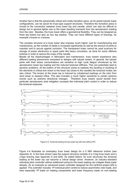
Figure 4.5: Torsional loading at truss-tower top with and without IPC<br />
Figure 4.4 illustrates an exemplary truss tower design for a 5 MW reference turbine (see<br />
Appendix A). In the here shown case the support structure consists of a 3-leg truss tower and a<br />
z-type bracing (see Appendix A and [24]). As stated before, for such structures the torsional<br />
loading at the tower top can become a critical design driver. However, an industry-standard<br />
individual pitch controller without additional tuning for the tower loading can mitigate these loads<br />
already. As an example an advanced power controller designed for the UpWind project [25] is<br />
applied. The controller includes 1P individual pitch control to reduce asymmetric rotor loads, and<br />
here especially 1P loads on rotating components and lower frequency loads on non-rotating


