


You also want an ePaper? Increase the reach of your titles
YUMPU automatically turns print PDFs into web optimized ePapers that Google loves.
UPWIND<br />
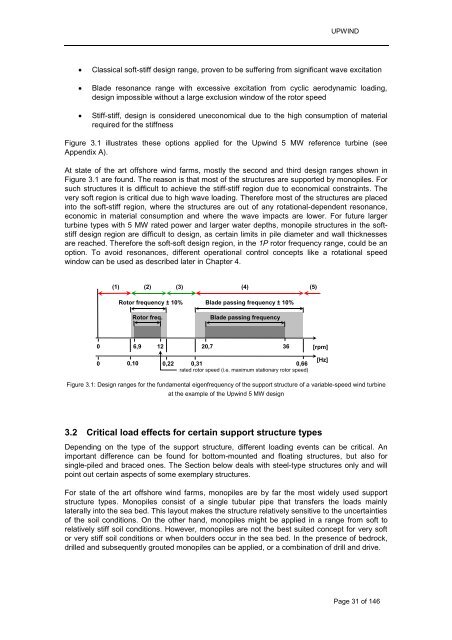
� Classical soft-stiff design range, proven to be suffering from significant wave excitation<br />
� Blade resonance range with excessive excitation from cyclic aerodynamic loading,<br />
design impossible without a large exclusion window of the rotor speed<br />
� Stiff-stiff, design is considered uneconomical due to the high consumption of material<br />
required for the stiffness<br />
Figure 3.1 illustrates these options applied for the Upwind 5 MW reference turbine (see<br />
Appendix A).<br />
At state of the art offshore wind farms, mostly the second and third design ranges shown in<br />
Figure 3.1 are found. The reason is that most of the structures are supported by monopiles. For<br />
such structures it is difficult to achieve the stiff-stiff region due to economical constraints. The<br />
very soft region is critical due to high wave loading. Therefore most of the structures are placed<br />
into the soft-stiff region, where the structures are out of any rotational-dependent resonance,<br />
economic in material consumption and where the wave impacts are lower. For future larger<br />
turbine types with 5 MW rated power and larger water depths, monopile structures in the softstiff<br />
design region are difficult to design, as certain limits in pile diameter and wall thicknesses<br />
are reached. Therefore the soft-soft design region, in the 1P rotor frequency range, could be an<br />
option. To avoid resonances, different operational control concepts like a rotational speed<br />
window can be used as described later in Chapter 4.<br />
0<br />
0<br />
(1)<br />
(2) (3)<br />
(4)<br />
(5)<br />
Rotor frequency ± 10%<br />
Rotor freq.<br />
Blade passing frequency ± 10%<br />
Blade passing frequency<br />
6,9 12 20,7 36 [rpm]<br />
0,10 0,22 0,31 0,66<br />
rated rotor speed (i.e. maximum stationary rotor speed)<br />
Figure 3.1: Design ranges for the fundamental eigenfrequency of the support structure of a variable-speed wind turbine<br />
at the example of the Upwind 5 MW design<br />
3.2 Critical load effects for certain support structure types<br />
Depending on the type of the support structure, different loading events can be critical. An<br />
important difference can be found for bottom-mounted and floating structures, but also for<br />
single-piled and braced ones. The Section below deals with steel-type structures only and will<br />
point out certain aspects of some exemplary structures.<br />
For state of the art offshore wind farms, monopiles are by far the most widely used support<br />
structure types. Monopiles consist of a single tubular pipe that transfers the loads mainly<br />
laterally into the sea bed. This layout makes the structure relatively sensitive to the uncertainties<br />
of the soil conditions. On the other hand, monopiles might be applied in a range from soft to<br />
relatively stiff soil conditions. However, monopiles are not the best suited concept for very soft<br />
or very stiff soil conditions or when boulders occur in the sea bed. In the presence of bedrock,<br />
drilled and subsequently grouted monopiles can be applied, or a combination of drill and drive.<br />
[Hz]<br />
Page 31 of 146


