


Create successful ePaper yourself
Turn your PDF publications into a flip-book with our unique Google optimized e-Paper software.
UPWIND<br />
successful if the benefit from adding fore-aft damping to the wave response compensates for<br />
the additional production-induced aerodynamic loads. This is in general the case for sites with<br />
larger water depths, where the wave-induced fatigue loads are governing.<br />
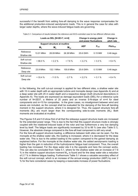
Table 5.1: Comparison of results between the reference and SCO-controlled case for two different offshore sites<br />
Reference<br />
Shallow site<br />
Soft cut-out<br />
Shallow site<br />
Reference<br />
Deep site<br />
Soft cut-out<br />
Deep site<br />
Page 54 of 146<br />
Loads as DEL [N=2E+7, m=4] Change in energy yield<br />
and power fluctuations<br />
Support structure at mudline<br />
AEP<br />
Mx My Mxy<br />
Pstd<br />
Change in<br />
pitch rate<br />
Pitchstd<br />
13.01 MNm 28.09 MNm 26.38 MNm 25.6 GWh 0.15 MW 0.46 deg/s<br />
+ 66.0 % + 2.2 % + 7.6 % + 2.2 % + 3.3 % + 6.4 %<br />
23.9 MNm 132.1 MNm 100.6 MNm 25.6 GWh 0.15 MW 0.46 deg/s<br />
+ 33.4 % - 11.5 % - 2.7 % + 2.2 % + 3.1 % + 6.4 %<br />
In the following, the soft cut-out concept is applied for two different sites, a shallow water site<br />
with 10 m water depth with an appropriate turbine and monopile design (see Appendix A) and at<br />
a deep water site with 25 m water depth and a respective design (both structural descriptions in<br />
Appendix A). The loads are expressed as damage equivalent loads (DEL) for a reference cycle<br />
number of N=2E07, a lifetime of 20 years and an inverse S-N-slope of m=4 for steel<br />
components and m=10 for composites. In the given cases, no misalignment between wind and<br />
waves are included, as the concept shall be evaluated for the damping of the fore-aft bending<br />
moment in the support structure, where it is designed for. Thus, the support structure fore-aft<br />
moments (My) are much larger than the corresponding side-to-side moments (Mx). Both<br />
moments are evaluated at mudline.<br />
The Figures 5.8 and 5.9 show first of all that the sideways support structure loads are increased<br />
for the extended power range. This is due to the fact that this support structure mode is strongly<br />
coupled with the rotational-induced loads of the rotor and has furthermore a very low damping<br />
level by itself. The fatigue loads are significantly increased by 33 to 66 % (see also Table 5.1).<br />
However, the absolute change compared to the fore-aft load component is still very small.<br />
For the fore-aft support structure loading, a difference between both sites can be seen. For the<br />
monopile at the shallow water site, the loading is increased, where it is decreased for the deep<br />
water site. This is due to the added loading to the system compared to the gained damping as<br />
explained before. For the monopile at the shallow water site, the added aerodynamic loading is<br />
higher than the gain in reduction of the hydrodynamic fatigue load component. Thus, the overall<br />
loading has increased. For the deep water site it is the opposite and here the concept works.<br />
This can also be concluded from Table 5.1, where for the shallow water site an increase of 7.6<br />
% in the relative support structure moment Mxy is found and for the deep water site a reduction<br />
of 2.7 % in lifetime fatigue loading. Furthermore Table 5.1 shows a valuable secondary effect of<br />
the soft cut-out concept, which is an increase of the annual energy production (AEP) by over 2<br />
% for the here considered cases by keeping a reasonable increase of power fluctuations.


