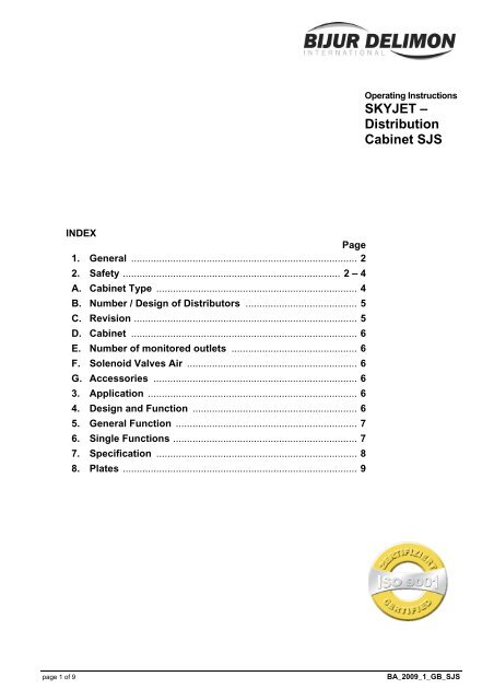
SKYJET – Distribution Cabinet SJS - Bijur Delimon
SKYJET – Distribution Cabinet SJS - Bijur Delimon
SKYJET – Distribution Cabinet SJS - Bijur Delimon

You also want an ePaper? Increase the reach of your titles
YUMPU automatically turns print PDFs into web optimized ePapers that Google loves.
INDEX<br />
Page<br />
1. General ................................................................................. 2<br />
2. Safety .............................................................................. 2 <strong>–</strong> 4<br />
A. <strong>Cabinet</strong> Type ........................................................................ 4<br />
B. Number / Design of Distributors ........................................ 5<br />
C. Revision ................................................................................ 5<br />
D. <strong>Cabinet</strong> ................................................................................. 6<br />
E. Number of monitored outlets ............................................. 6<br />
F. Solenoid Valves Air ............................................................. 6<br />
G. Accessories ......................................................................... 6<br />
3. Application ........................................................................... 6<br />
4. Design and Function ........................................................... 6<br />
5. General Function ................................................................. 7<br />
6. Single Functions .................................................................. 7<br />
7. Specification ........................................................................ 8<br />
8. Plates .................................................................................... 9<br />
Operating Instructions<br />
<strong>SKYJET</strong> <strong>–</strong><br />
<strong>Distribution</strong><br />
<strong>Cabinet</strong> <strong>SJS</strong><br />
page 1 of 9 BA_2009_1_GB_<strong>SJS</strong>
1. General<br />
Prior to start up, we recommend to read these operating instructions carefully as we do not assume any<br />
liability for damages and operating troubles which result from the nonobservance of these operating<br />
instructions!<br />
Any use beyond the applications described in these operating instructions is considered to be not in<br />
accordance with the product’s intended purposes. The manufacturer is not to be held responsilbe for any<br />
damages resulting from this: the user alone bears the corresponding risk.<br />
As to figures and indications in these operating instructions we reserve the right to make technical changes<br />
which might become necessary for improvements.<br />
The copyright on these operating instructions is kept reserved to the company DELIMON. These operating<br />
instructions are intended for the erecting, the operating and supervising personnel. They contain<br />
regulations and drawings of technical nature which must not <strong>–</strong> completely or partially - be distributed nor<br />
used nor communicated to others without authorization for competition purposes.<br />
Company address, spare parts and service address<br />
DELIMON Branch office<br />
Arminstraße 15 Am Bockwald 4<br />
D-40277 Düsseldorf D-08344 Grünhain-Beierfeld<br />
Phone : +49 211 77 74-0 E-mail : kontakt@bijurdelimon.com<br />
Fax : +49 211 77 74-210 www.bijurdelimon.com<br />
2. Safety<br />
These operating instructions contain fundamental instructions which are to be observed during erection,<br />
operation and maintenance. Therefore it is absolutely necessary for the fitter and the competent qualified<br />
staff/user to read these operating instructions before installation and start-up. The operating instructions<br />
must be available at all times at the place of use of the machine/system.<br />
Not only the general safety instructions stated under this main point “safety“ are to be observed, but also<br />
the other specific safety instructions stated under the other main points.<br />
2.1 Identification of safety warnings in the operating instructions<br />
The safety warnings contained in these operating instructions which, if not observed, may cause dangers to<br />
people, are specially marked with general danger symbols<br />
safety sign according to DIN 4844, warning about a danger spot ,<br />
in case of warning about electric voltage with<br />
safety sign according to DIN 4844, warning about dangerous electric voltage.<br />
In case of safety instructions which, if not observed, may cause damage to the machine and its function,<br />
the word<br />
ATTENTION<br />
is inserted.<br />
Instructions that are directly attached to the machine, as for example<br />
• rotational direction arrow<br />
• identifications for fluid connections<br />
must be observed at all events and maintained in a fully legible condition.<br />
• Note: There is an increased skid risk in case of spilled/leaked out lubricants. They are to be removed<br />
at once properly.<br />
Safety sign according to DIN 4844, warning about skid risk.<br />
page 2 of 9 BA_2009_1_GB_<strong>SJS</strong>
2. Safety (continuation)<br />
2.2 Personnel qualification and training<br />
The operating, maintaining, inspecting and erecting personnel must have the appropriate qualification for<br />
such work. Area of responsibility, competence and supervision of the personnel have to be regulated by<br />
the user. If the personnel do not have the necessary knowledge, they have to be trained and given<br />
instructions. This can be effected, if necessary, by the manufacturer/supplier on behalf of the user of the<br />
machine. Furthermore, the user has to make sure that the contents of the operating instructions are fully<br />
understood by the personnel.<br />
2.3 Dangers in case of nonobservance of the safety instructions<br />
The nonobservance of the safety instructions may result in hazards to persons, to the environment and to<br />
the machine. The nonobservance of the safety instructions may lead to the loss of any claims for damages.<br />
In detail, the nonobservance may for instance lead to the following hazards:<br />
• Failure of important functions of the machine/system<br />
• Failure of prescribed methods for maintenance and repair<br />
• Harzard to persons by electrical, mechanical and chemical influences<br />
• Hazard to the environment by the leakage of dangerous substances<br />
2.4 Safety conscious working<br />
The safety instructions stated in these operating instructions, the existing national regulations as to the<br />
accident preventation as well as possible internal working, operating and safety rules of the user are to be<br />
observed.<br />
2.5 Safety instructions for the user/operator<br />
• If hot or cold machine parts lead to dangers, these parts have to be protected against touch.<br />
• Protection against touch for moving parts (e. g. coupling) must not be removed when the machine is in<br />
operation.<br />
• Leakages (e. g. from the shaft seal) of hazardous goods to be delivered (e. g. explosive, toxic, hot)<br />
are to be removed in such a way that there is no danger to persons and environment. Legal rules are<br />
to be ovserved. .<br />
• Hazards caused by electrial power are to be excluded (for details please refer for instance to the rules<br />
of the VDE and the local power supply companies).<br />
2.6 Safety instructions for maintenance, inspection and installation work<br />
The user has to take care that all the maintenance, inspection and installation work is executed by<br />
authorized and qualified skilled personnel who have informed themselves adequately by thoroughly<br />
studying the operating instructions.<br />
Basically, work on the machine is only to be carried out during shut-down. It is obligatory to observe the<br />
shut-down procedure described in the operating instructions .<br />
Pumps or pump aggregates that deliver media being hazardous to health have to be decontaminated.<br />
Immediately after completion of the work, all safety and protective equipments have to be reinstalled and/or<br />
reactivated.<br />
• Advice: When working with compressed air, do wear glasses.<br />
(DIN 4844 <strong>–</strong> Use breathing mask)<br />
• Advice: Observe EC-Safety Data Sheet for materials of consumption and additives used and use<br />
personal protective equipment.<br />
(DIN 4844 <strong>–</strong> Use breathing mask)<br />
Before recommissioning, observe the points stated in section “initial start-up“.<br />
page 3 of 9 BA_2009_1_GB_<strong>SJS</strong>
2. Safety (continuation)<br />
2.7 Unauthorized conversion and manufacture of spare parts<br />
Conversion or modifications to the machine are only permitted when agreed with the manufacturer. Original<br />
spare parts and accessories authorized by the manufacturer serve to ensure safety. The use of other parts<br />
may render the liability for consequencial losses null and void.<br />
2.8 Unacceptable modes of operation<br />
The operational reliability of the machine supplied is only guaranteed if the machine is used in accordance<br />
with its intended purposes as per section 1 - General - of the operating instructions. The limiting values<br />
specified in the data sheet must on no account be exceeded.<br />
2.9 Guidelines & standards<br />
1., 2. and 3. guideline (see data sheet: R&N_2009_1_GB)<br />
3.0 Notes on environmental protection and waste disposal<br />
In correct operation with lubricants, the components are subject to the special requirements set by<br />
environmental legislation.<br />
The general requirements for lubricants are specified in the respective safety data sheets.<br />
Used lubricants are hazardous forms of waste and therefore require special supervision in the sense of §<br />
41 paragraph 1 sentence 1 and paragraph 3 no. 1 of KrW-/AbfG (Closed-Loop Waste Management Act).<br />
Used oils must be handled in compliance with AltölV (Waste Oil Ordinance).<br />
The devices or components contaminated with lubricant must be disposed of by a certified waste<br />
management company.<br />
Records of proper waste management must be filed in conformance to NachwV (Ordinance on Waste<br />
Recovery and Disposal Records).<br />
page 4 of 9 BA_2009_1_GB_<strong>SJS</strong>
GENERAL PRODUCT CHARACTERISTICS<br />
• Distributor unit for air-oil lubrication<br />
• Completely mounted in a cabinet<br />
• Including filter regulator (40 μm) and misc. monitoring and shut-off devices<br />
• Optional monitoring for each lubrication line by means of sensor<br />
• Terminal box<br />
A. CABINET TYPE <strong>SJS</strong><br />
B. NUMBER / DESIGN OF DISTRIBUTORS<br />
1 x 1 outlet ZAG04A020224BFFF00<br />
1 x 2 outlets ZAG04A020224BFBF00<br />
1 x 3 outlets ZAG04A020224BJJF00<br />
1 x 4 outlets ZAG04A020224BBBB00<br />
1 x 5 outlets ZAG04A020224AIFB00<br />
1 x 6 outlets ZAG04A020224AIIF00<br />
1 x 7 outlets ZAG04A020224AIIJ00<br />
1 x 8 outlets ZAG04A020224AAAA00<br />
C. REVISION<br />
Status A<br />
page 5 of 9 BA_2009_1_GB_<strong>SJS</strong>
D. CABINET<br />
Steel W x H x D 760 x 760 x 210 (1 x distributor with 1 to 4 outlets)<br />
Steel W x H x D 760 x 760 x 210 (1 x distributor with 5 to 8 outlets)<br />
E. NUMBER OF MONITORED OUTLETS<br />
without<br />
1 outlet<br />
2 outlets<br />
3 outlets<br />
4 outlets<br />
5 outlets<br />
6 outlets<br />
7 outlets<br />
8 outlets<br />
F. SOLENOID VALVES AIR<br />
without<br />
1 x 2/2-way solenoid valve 24 V DC<br />
1 x 2/2-way solenoid valve 110 V AC<br />
1 x 2/2-way solenoid valve 230 V AC<br />
G. ACCESSORIES<br />
without<br />
3. Application<br />
The <strong>SKYJET</strong> distributor cabinet serves to dose and distribute the air-oil mixture to the relevant lube points.<br />
The cabinet (in larger-size facilities several cabinets) is arranged in a decentralized location. Oil supply is<br />
accomplished via the upstream oil lubrication unit.<br />
4. Design and Function<br />
The distributor cabinet accommodates a filter regulator with pressure gauge for compressed-air supply and<br />
a socket ball cock. Compressed-air feed is via a downstream 2/2-way solenoid valve. The air pressure is<br />
monitored by a suitable pressure switch. <strong>Distribution</strong> of the oil volume is accomplished via a progressive<br />
group-lubrication distributor. The design of the outlets depends on the requirements of the system. An<br />
upstream 2/2-way solenoid valve takes care of controlling the oil feed to the progressive distributor.<br />
Distributor monitoring is ensured by a proximity switch within the mix block. All electrical components are<br />
wired up to a terminal block in a terminal box.<br />
page 6 of 9 BA_2009_1_GB_<strong>SJS</strong>
5. General Function<br />
The air pressure set at the filter regulator should be approx. 6 bar. The mix block fed with compressed air<br />
and metered oil volume produces an air-oil mixture which is carried in pipelines to the downstream <strong>SKYJET</strong><br />
distributors or directly to the lube points. To perform a lubricating cycle, the central electrical control system<br />
first of all opens the solenoid valve for oil feed. On completion of the distributor cycle, the proximity switch<br />
first cuts out the solenoid valve and then the pump. The compressed air is permanently connected.<br />
6. Single Functions<br />
Filter regulator (16220-4223)<br />
The filter regulator comprises a filter with automatic tank emptying. Installed downstream of the filter is a<br />
pressure reducing valve with excess-pressure control provision. The device serves for compressed-air<br />
cleaning and control.<br />
Socket ball cock (73631-1643)<br />
The socket ball cock is installed upstream of the filter controller to interrupt the connection to the<br />
compressed-air mains during maintenance and repair work.<br />
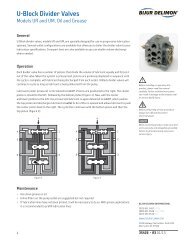
Progressive group-lubrication distributor ZP-A/G<br />
The Progressive group-lubrication distributor ZP-A/G is a progressive distributor with flanged mounted 2/2<br />
way solenoid valve, integrated filter and throttle. The progressive distributor consist of 3 up to maximum 4<br />
individual segments, which are screwed with each other and sealed against each other. Dependent on the<br />
arrangement in the distributor, the individual segments are manufactured as an initial- or A-segment, as a<br />
medium or M-segment as well as a final- or E-segment.<br />
Triggered by a signal of the electric control system, the 2/2-way solenoid valve opens, and lubricant is<br />
supplied under pressure via the filter and the throttle to the progressive distributor. Then the lubricant is<br />
divided into partial quantities, which are carried one after the other to the up to 8 possible outlets. The<br />
progressive distributor is fitted with two motion indicators, which make an electrical operational monitoring<br />
of the progressive group-lubrication distributor ZP-A/G possible.<br />
Mix block<br />
The mixing block is a distributor block with up to four outlets. It is used for injecting oil into the air flow, thus<br />
creating a homogeneous oil-air-mix. The oil feed-in is done by a progressive group-lubrication distributor,<br />
the air is provided by an air service unit. Monitoring of the air flow is optional and done with a separate flow<br />
monitor in each outlet (48741S008).<br />
2/2-way solenoid valve, compressed air (38152....)<br />
The 2/2-way solenoid valve opens and closes the compressed-air feed line from the filter controller to the<br />
group-lubrication distributor.<br />
Pressure switch (34241D040)<br />
The pressure switch serves to monitor the air pressure. If air pressure drops to below the as-set value, a<br />
fault alarm is given out in the electrical control system.<br />
Terminal box<br />
The terminal box serves for the wiring or cabling of all electronic components.<br />
Monitoring switch (66925-1311)<br />
The monitoring switch attached to the group-lubrication distributor enables precise monitoring and control<br />
of the distributor cycles and hence of the oil volumes fed to the relevant outlets.<br />
page 7 of 9 BA_2009_1_GB_<strong>SJS</strong>
7. Specification<br />
Filter regulator, 16220-4223<br />
Connecting thread .................................................................................................................................. G 1/2<br />
Operating medium .................................................................................................................. compressed air<br />
Operating pressure max.. ...................................................................................................................... 10 bar<br />
Temperature range ................................................................................. + 1 to 50°C, with dry air up to -20°C<br />
Filter element .......................................................................................................................... 40 μm standard<br />
Emptying ........................................................................................................................................... automatic<br />
Secondary pressure range .......................................................................................................... 0.3 to 10 bar<br />
Weight ................................................................................................................................................... 0.7 kg<br />
Socket ball cock, 73631-1643<br />
Connecting thread .................................................................................................................................. G 1/2<br />
Nominal pressure ................................................................................................................................... 65 bar<br />
Nominal width ........................................................................................................................................ DN 15<br />
Admissible operating temperature ......................................................................................... - 20 to + 170 °C<br />
Weight ............................................................................................................................................... 0.265 kg<br />
Pressure gauge, 75111-9293<br />
Indicating range ................................................................................................................................ 0 - 60 bar<br />
Connection .......................................................................................................................... R 1/4 to the back<br />
Diameter ............................................................................................................................................... 63 mm<br />
Filling fluid ............................................................................................................................................ glycerin<br />
Weight ................................................................................................................................................. 0.75 kg<br />
Progressive group-lubrication distributor ZP-A/G<br />
Dosing volume ..................................................................................................................... 0.1 / 0.2 / 0.3 cm³<br />
Outlets .................................................................................................................................................... 1 to 8<br />
Response pressure ............................................................................................................................... 10 bar<br />
Admissible lubricants ....................................................................... ISO VG 68 to 1500 (DIN 51519) at 20°C<br />
Temperature range ........................................................................................................................ 0 to + 80°C<br />
Operating pressure .............................................................................................................................. 160 bar<br />
2/2-way solenoid valve, 38152....<br />
Nominal pressure ................................................................................................................................ 400 bar<br />
Medium ........................................................................................................................................... grease, oil<br />
Seal ............................................................................................................................................... NBR 90 Sh<br />
Voltage ............................................................................................................................................... 24 V DC<br />
Weight ............................................................................................................................................ ca. 0.83 kg<br />
Temperature medium max. .................................................................................................................... 70 °C<br />
Flow rate Q max. ................................................................................................................................. 15 l/min<br />
2/2-way solenoid valve, 38152-<br />
Connecting thread .................................................................................................................................. G 1/2<br />
Nominal pressure .................................................................................................................................. 16 bar<br />
Nominal width ........................................................................................................................................ DN 16<br />
Medium ................................................................................................................................... compressed air<br />
Seal .......................................................................................................................................................... NBR<br />
Voltage ............................................................................................................ 24 V DC / 110V AC / 230V AC<br />
Weight ...................................................................................................................................... approx. 0.8 kg<br />
Pressure switch, 34241D040<br />
Connecting thread ..................................................................................................................................... G ¼<br />
Adjusting range .......................................................................................................................... 0.5 … 10 bar<br />
Burst strenght ........................................................................................................................................ 25 bar<br />
Switching frequency ...................................................................................................................... 50 Mio/min.<br />
Ambient temperature / medium temperature ........................................................................... - 25 to + 80 °C<br />
Operating voltage .................................................................................................................... 9.6 … 32 V DC<br />
Type of protection .................................................................................................................................... IP 67<br />
Monitoring switch, 66925-1311<br />
Operating voltage ....................................................................................................................... 10V to 30V D<br />
Switching function ......................................................................................................................... NO contact<br />
Switching frequency .................................................................................................................. max. 1000 Hz<br />
Temperature range .................................................................................................................... - 25 to + 70°C<br />
Type of protection ......................................................................................................... IP 65 in plugged state<br />
page 8 of 9 BA_2009_1_GB_<strong>SJS</strong>
8. Plates<br />
Name plate 110 x 60 mm (75511-1531) Type plate 110 x 60 mm (75511-1321)<br />
page 9 of 9 BA_2009_1_GB_<strong>SJS</strong>