TTK70: Absolute, non-contact linear measuring system ... - Mysick.com
TTK70: Absolute, non-contact linear measuring system ... - Mysick.com
TTK70: Absolute, non-contact linear measuring system ... - Mysick.com

Create successful ePaper yourself
Turn your PDF publications into a flip-book with our unique Google optimized e-Paper software.
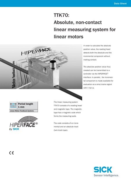
Period length<br />
1 mm<br />
Linear Motor Feedback Systems<br />
<strong>TTK70</strong>:<br />
<strong>Absolute</strong>, <strong>non</strong>-<strong>contact</strong><br />
<strong>linear</strong> <strong>measuring</strong> <strong>system</strong> for<br />
<strong>linear</strong> motors<br />
The <strong>linear</strong> <strong>measuring</strong> <strong>system</strong><br />
<strong>TTK70</strong> consists of a reading head<br />
and magnetic tape. The magnetic<br />
tape has a magnetic code which<br />
forms the <strong>measuring</strong> scale.<br />
The code consists of an incre-<br />
mental and an absolute track<br />
(twin-track tape).<br />
In order to calculate the absolute<br />
position value, the reading head<br />
detects both the absolute and the<br />
incremental <strong>com</strong>ponent without<br />
making <strong>contact</strong>.<br />
The absolute position value thus<br />
created can be transmitted to a<br />
controller via the HIPERFACE ®<br />
interface. In parallel, the incremental<br />
<strong>com</strong>ponent is made available for<br />
evaluation as a sine/cosine signal<br />
with 1 Vp-t-p.<br />
Data Sheet
Linear Motor Feedback Systems with HIPERFACE ® <strong>TTK70</strong><br />
Period length<br />
1 mm<br />
Linear Motor Feedback Systems<br />
▀ Measurement length up to 4 m<br />
▀ Non-<strong>contact</strong> length <strong>measuring</strong><br />
<strong>system</strong>, wear-free<br />
▀ <strong>Absolute</strong> position determination,<br />
no reference run<br />
▀ Length-independent position<br />
sensing time<br />
▀ Electronically adjustable<br />
Protection class up to IP 65<br />
Product may differ from illustration<br />
Accessories<br />
Connection <strong>system</strong>s (page 7)<br />
Programming Tool (page 7)<br />
Dimensions and positional tolerances<br />
M12 x 1<br />
14 (0.55)<br />
14 (0.55)<br />
5.3<br />
(0.21)<br />
30 (1.18)<br />
1) Without cover strip<br />
2) With cover strip<br />
PIN and wire allocation<br />
View of the<br />
plug-in face<br />
23.6 (0.93)<br />
PIN Colour of wires Signal Explanation<br />
1 brown REFSIN Process data channel<br />
2 white + SIN Process data channel<br />
3 black REFCOS Process data channel<br />
4 pink + COS Process data channel<br />
5 grey or yellow Data + RS-485 Parameter channel<br />
6 green or purple Data – RS-485 Parameter channel<br />
7 blue GND Ground connection<br />
8 red + Us Encoder Supply voltage<br />
Screen Housing potential<br />
Screening via plug housing<br />
Electronically adjustable via<br />
Programming Tool<br />
2 T T K 7 0 W I T H H I P E R FA C E ® 2 0 1 1 - 0 1<br />
Subject to change without notice<br />
5.5<br />
(0.22)<br />
8<br />
(0.31)<br />
10<br />
(0.39)<br />
61.5 (2.42)<br />
40 (1.58)<br />
70 (2.76)<br />
5.5 (0.22)<br />
6.6 (0.26)<br />
13 (0.51)<br />
0<br />
10–0.1<br />
(0.39)<br />
All dimensions in mm (inch)<br />
General tolerances according to DIN ISO 2768-mk
Technical data to DIN 32878 <strong>TTK70</strong> HIPERFACE ®<br />
Period length 1 mm<br />
Max. measurement length 4,000 mm<br />
Magnetic tape length Measurement length + 80 mm<br />
Dimensions mm (see dimensional drawing)<br />
Max. distance ot the sensor to the magnetic tape<br />
without cover strip 0.3 mm<br />
with cover strip 0.2 mm<br />
Mass read head 0.08 kg<br />
magnetic tape 0.18 kg/m<br />
Material read head zinc diecasting<br />
magnetic tape 17410 Hard ferrite 9/28 P<br />
Code type for the absolut value Binary<br />
Measurement step at interpolation of the sine/cosine signals<br />
with e. g. 12 bits 0.244 µm<br />
System accuracy (at 20 °C ambient temperature)<br />
< ± 10 µm<br />
Repeatability < 5 µm<br />
Hysteresis error < 10 µm<br />
Operating speed up to which the absolute position<br />
can be reliably produced 1.3 m/s<br />
Max. operating speed 10 m/s<br />
Permitted mounting tolerance See dimensional drawing page 2<br />
Working temperature range –30 … +80 °C<br />
Storage temperature range –40 … +100 °C (without packaging)<br />
Permissible relative humidity 100 % (condesation permitted)<br />
Temperature coefficient magnetic tape (11 ± 1) x 10-6 /K<br />
Maximum permitted ambient field strength to guarantee <strong>com</strong>pliance<br />
with the quoted accuracy values 1) < 3 .. 4 kA/m (3.8 .. 5 mT)<br />
Maximum permitted field strength to ensure that the magnetic tape<br />
is not permanently damaged<br />
Resistance (read head)<br />
< 150 kA/m (< 190 mT)<br />
to shocks to EN 60068-2-27 30 g/6 ms<br />
to vibration to EN 60068-2-6 20 g/10 … 2,000 Hz<br />
Protection class to IEC 60529 2) IP 65<br />
EMC 3)<br />
Operating voltage range 7 … 12 V<br />
Re<strong>com</strong>mended supply voltage 8 V<br />
Max. operating current, no load < 65 mA 4)<br />
Available memory area<br />
within EEPROM 2048 5) Interface signals<br />
1,792 bytes<br />
Process data channel = SIN, REFSIN, COS, REFCOS Analogue, differential<br />
Parameter channel = RS 485 Digital<br />
1) The maximum permitted external field influence is reached when the position value<br />
deviates from the original value (without external field influence) by more than 5 µm.<br />
This value is reached when, at the sensor location, a field strength of 3 … 4 kA/m<br />
(3.8 .. 5 mT) occurs in addition to the field strength of the magnetic tape.<br />
2) With mating plug mounted<br />
3) To EN 61000-6-2 and EN 61000-6-3<br />
The EMC according to the standards quoted is achieved when the motor feedback<br />
<strong>system</strong> is mounted in an electrically conductive housing, which is connected to the<br />
central earthing point of the motor controller via a cable screen.<br />
The GND (0V) connection of the supply voltage is also connected to earth there.<br />
Users must perform their own tests when other screen designs are used.<br />
4) 100 mA approx. during adjustment<br />
5) If applying the electronic type label, in connection with numeric controllers, attention<br />
should be paid to Patent EP 425 912 B 2; Application of the electronic type label in<br />
connection with speed regulation is exempt.<br />
1 Magnetic tape Working temperature range –20 ... +70 °C<br />
Storage temperature range –30 ... +80 °C<br />
2 0 1 1 - 0 1<br />
Subject to change without notice<br />
Ordering information<br />
Length <strong>measuring</strong> <strong>system</strong> <strong>TTK70</strong><br />
Model name<br />
<strong>TTK70</strong>-HXA0-K02<br />
Part no.<br />
1037434<br />
Description<br />
Read head<br />
Ordering information<br />
Magnetic tape with adhesive tape and cover band incl. 1<br />
Model name<br />
Part no. Description<br />
MVM-0M5-2MC-MKLB<br />
6037415<br />
Magnetic tape 0.5 m<br />
MVM-01M-2MC-MKLB<br />
6037417<br />
Magnetic tape 1.0 m<br />
MVM-1M5-2MC-MKLB<br />
6037418<br />
Magnetic tape 1.5 m<br />
MVM-02M-2MC-MKLB<br />
6037419<br />
Magnetic tape 2.0 m<br />
MVM-2M5-2MC-MKLB<br />
6037420<br />
Magnetic tape 2.5 m<br />
MVM-03M-2MC-MKLB<br />
6037421<br />
Magnetic tape 3.0 m<br />
MVM-3M5-2MC-MKLB<br />
6037422<br />
Magnetic tape 3.5 m<br />
MVM-04M-2MC-MKLB<br />
6037423<br />
Magnetic tape 4.0 m<br />
T T K 7 0 W I T H H I P E R FA C E ®<br />
<strong>TTK70</strong><br />
3
Linear Motor Feedback Systems with HIPERFACE ® <strong>TTK70</strong><br />
Further informations to the interface<br />
see HIPERFACE ® -description<br />
part no. 8010701<br />
Electrical interface<br />
• Safe data transmission • Only 8 leads<br />
• High information content • Bus-enabled parameter channel<br />
• Electronic type label • Process data channel in real time<br />
Signal specification of the process data channel<br />
Access to the process data used for speed Sophisticated technology guarantees stable<br />
control, i.e. to the sine and cosine signals, is amplitudes of the analogue signals across all<br />
practically always "online". When the supply volt- specified environmental conditions, with a maxiage<br />
is applied, the speed controller has access<br />
to this information at any time.<br />
mum variation of only 20 %.<br />
Characteristics applicable to all permissible environmental conditions<br />
Signal Value/Units<br />
Signal peak, peak Vss of SIN, COS 0.9 … 1.1 V<br />
Signal offset REFSIN, REFCOS 2.2 … 2.8 V<br />
Re<strong>com</strong>mended receiver circuit for sine and cosine signals<br />
The output circuit of the process data channel within the SinCos encoder<br />
4 T T K 7 0 W I T H H I P E R FA C E ® 2 0 1 1 - 0 1<br />
Subject to change without notice
1) The <strong>linear</strong> length <strong>measuring</strong> <strong>system</strong><br />
supports the following baud rates: 9600,<br />
19200 and 38400.<br />
2) The <strong>com</strong>mands thus labelled include<br />
the parameter "Code 0".<br />
Code 0 is a byte inserted into the<br />
protocol, for additional safeguarding<br />
of vital <strong>system</strong> parameters against<br />
accidental overwriting.<br />
When shipped, "Code 0" = 55h.<br />
3) The temperature value will be reliably<br />
formed approx. 2 s after power on/reset.<br />
Further informations to the interface<br />
see HIPERFACE ® -description<br />
part no. 8010701<br />
2 0 1 1 - 0 1<br />
Subject to change without notice<br />
Type-specific settings <strong>TTK70</strong><br />
Type ID (<strong>com</strong>mand 52h) FFh<br />
Free EEPROM [bytes] 1,792<br />
Address 40h<br />
Mode_485 1) E4h<br />
Codes 0 … 3 55h<br />
Counter 0<br />
Overview of <strong>com</strong>mands supported <strong>TTK70</strong><br />
Command byte<br />
42h<br />
43h<br />
44h<br />
46h<br />
47h<br />
49h<br />
4Ah<br />
4Bh<br />
4Ch<br />
4Dh<br />
4Eh<br />
4Fh<br />
50h<br />
52h<br />
53h Encoder reset<br />
55h Allocate encoder address<br />
•<br />
56h Read serial number and program version<br />
57h Configure serial interface<br />
•<br />
67h Change serial interface temporary<br />
6Ah Set position with internal synchronization • see page 6<br />
6Bh Sensor adjustment (during <strong>com</strong>missioning) •<br />
Overview of status messages<br />
Function Code 0 2)<br />
Read position (5 bits per sine/cosine period)<br />
Set position<br />
Read analogue value<br />
Read counter<br />
Increase counter<br />
Reset counter<br />
Read data<br />
Save data<br />
Determine status of a data field<br />
Create data field<br />
Determine available memory area<br />
Change access code<br />
Read encoder status<br />
Read out name plate<br />
Comments<br />
31.25 µm<br />
Channel number 48h<br />
Temperature [°C] 3)<br />
Encoder type = FFh<br />
Error type Status code Description <strong>TTK70</strong><br />
00h The encoder has recognised no error •<br />
02h Faulty internal angular offset<br />
•<br />
03h Data field partitioning table damaged<br />
•<br />
04h Analogue limit values not available<br />
•<br />
05h Internal I •<br />
2 Initialisation 01h Adjustment data faulty •<br />
C bus not operational<br />
06h Internal checksum error<br />
•<br />
Protocol 09h Parity error<br />
•<br />
0Ah Checksum of the data transmitted is incorrect<br />
•<br />
0Bh Unknown <strong>com</strong>mand code<br />
•<br />
0Ch Number of data transmitted is incorrect<br />
•<br />
0Dh Command argument transmitted is not allowed<br />
•<br />
Data 0Eh The selected data field must not be written to •<br />
0Fh Incorrect access code •<br />
10h Size of data field stated cannot be changed •<br />
11h Word address stated, is outside data field •<br />
12h Access to <strong>non</strong>-existent data field •<br />
Position 20h Sensor is not adjusted or is in adjustment mode. •<br />
21h Distance magnetic tape/sensor too high •<br />
23h Positional error •<br />
Other 1Ch Monitoring the value of the analogue signals (process data) •<br />
1Eh Encoder temperature critical •<br />
08h Counter overflow •<br />
•<br />
•<br />
T T K 7 0 W I T H H I P E R FA C E ®<br />
<strong>TTK70</strong><br />
5
Description HIPERFACE ® -Commands <strong>TTK70</strong><br />
Set position with internal synchronization 6 Ah<br />
address 6Ah Pos_HH Pos_HL Pos_LH Pos_LL Code 0 checksum<br />
address 6Ah PosNeu_HH PosNeu_HL PosNeu_LH PosNeu_LL checksum<br />
With this <strong>com</strong>mand, the encoder position is set such that the required position value points to the beginning of a period<br />
of the SIN signal. This is achieved by not changing, in contrast to the<br />
<strong>com</strong>mand “Set position” (43h), the lower 5 bits of the position value, as these are responsible for the interpolation within<br />
a period.<br />
The position value given in the <strong>com</strong>mand is transmitted in the “unsigned long” format with the LSB right-aligned and<br />
saved to <strong>non</strong>-volatile memory. The value range is between 0 .. 127999 and must be interpreted as a multiple of 1/32mm.<br />
The following events trigger an error message:<br />
• Number of transmitted <strong>com</strong>mand bytes wrong (WRONG_COMMAND_LENGTH, 0Ch)<br />
• Wrong access code entered (ERR_ACCESS_CODE, 0Fh),<br />
• Internal error occurred, which would lead to an invalid position value (ERR_INT_ANGLE_OFFSET, 02h),<br />
• Encoder is not adjusted (ERR_NOT_CALIBRATED, 20h),<br />
• Transmitted <strong>com</strong>mand argument is invalid (WRONG_ARGUMENT, 0Dh),<br />
• Internal checksum error (ERR_CHKSUM, 06h)<br />
5 LSB<br />
of the digital<br />
absolute position<br />
Codification magnetic tape<br />
The absolute coding of the magnetic tape allows a max. <strong>measuring</strong> range of 4095.999mm. As the resolution of the<br />
position data is 1/32 mm, the resulting numeric value for the maximum <strong>measuring</strong> range is 131072.<br />
0 0<br />
+131071 +1 +131071 +1<br />
Internal position calculation <strong>TTK70</strong><br />
Position value (-3072 .. 00 .. +127999):<br />
To avoid rapid jumps to the maximum value, around the 0 position, the max. <strong>measuring</strong> range is limited to 4000mm<br />
(= 128000 * 1/32mm). Therefore, in the negative direction of travel, a range of -96mm (= -3072 * 1/32mm)<br />
can be detected.<br />
0<br />
+127999 -3072 -1 +1 +127999 -3072 -1 +1<br />
Due to the positional calculations performed inside the <strong>TTK70</strong>, during <strong>com</strong>missioning it is necessary to send the <strong>com</strong>-<br />
mand "6Ah" (Position set with internal synchronisation) at the start of the magnetic tape.<br />
– Sine<br />
– Cosine<br />
6 T T K 7 0 W I T H H I P E R FA C E ® 2 0 1 1 - 0 1<br />
Subject to change without notice<br />
0
Dimensional drawings and ordering information<br />
Round screw <strong>system</strong> M12<br />
Cable connector M12 male, 8-pin, straight, screened,<br />
for field assembly (adapter side)<br />
Model name<br />
STE-1208-GA<br />
Part no.<br />
6028370<br />
2 0 1 1 - 0 1<br />
Subject to change without notice<br />
Contacts/cable diameter<br />
8 / 4 … 8 mm<br />
All dmensions in mm (inch)<br />
Cable connector M12 female, 8-pin, angled, screened,<br />
for field assembly (adapter side)<br />
Model name<br />
DOS-1208-WA<br />
SW 13<br />
Female connector M12, 8-pin, straight, pre-wired with cable<br />
8-wire, 4 x 2 x 0.25 mm 2 , screened, flexible (adapter side)<br />
Model name<br />
DOL-1208-G02MAC1<br />
Part no.<br />
6032866<br />
DOL-1208-G05MAC1 6032867<br />
DOL-1208-G10MAC1 6032868<br />
DOL-1208-G20MAC1 6032869<br />
Contacts<br />
8<br />
8<br />
8<br />
8<br />
All dimensions in mm (inch)<br />
Cable HIPERFACE ® , 8 wires, per metre 4 x 2 x 0,15 mm 2<br />
Model name<br />
LTG-2708-MW<br />
Ø 19<br />
(0.75)<br />
M12<br />
approx. 41 (1.61)<br />
Part no.<br />
6043358<br />
approx. 48 (1.89)<br />
Part no.<br />
6028361<br />
Contacts/cable diameter<br />
8 / 4 … 8 mm<br />
All dimensions in mm (inch)<br />
Wires<br />
8<br />
Cable length „L“<br />
2,0 2.0 m<br />
2,0 5.0 m<br />
2,0 10.0 m<br />
20.0 m<br />
Accessories Connection Systems/Programming Tool<br />
Cable connector M12 female, 8-pin, straight, screened,<br />
for field assembly (adapter side)<br />
Model name<br />
DOS-1208-GA<br />
Part no.<br />
6028369<br />
Contacts/cable diameter<br />
8 / 4 … 8 mm<br />
All dimensions in mm (inch)<br />
Right angled M12, 8-pin female connector, pre-wired with cable<br />
8 cores, 4 x 2 x 0.25mm 2 , screened, suitable for use in a drag chain (adapter side)<br />
Model name<br />
DOL-1208-W02MAC1<br />
Part no.<br />
6037724<br />
DOL-1208-W05MAC1 6037725<br />
DOL-1208-W10MAC1 6037726<br />
DOL-1208-W20MAC1 6037727<br />
Programming Tool<br />
Cores<br />
8<br />
8<br />
8<br />
8<br />
All dimensions in mm (inch)<br />
Programming Tool for <strong>TTK70</strong> with HIPERFACE ® interface<br />
Model name<br />
PGT-03-S<br />
Part no.<br />
1034252<br />
Cable length „L“<br />
2,0 2.0 m<br />
2,0 5.0 m<br />
2,0 10.0 m<br />
20.0 m<br />
T T K 7 0 W I T H H I P E R FA C E ®<br />
7
8012887/2011-01-27 ∙ SF (2011-01) ∙ A4 2c int35a<br />
Australia<br />
Phone +61 3 9497 4100<br />
1800 33 48 02 – tollfree<br />
E-Mail sales@sick.<strong>com</strong>.au<br />
Belgium/Luxembourg<br />
Phone +32 (0)2 466 55 66<br />
E-Mail info@sick.be<br />
Brasil<br />
Phone +55 11 3215-4900<br />
E-Mail sac@sick.<strong>com</strong>.br<br />
Ceská Republika<br />
Phone +420 2 57 91 18 50<br />
E-Mail sick@sick.cz<br />
China<br />
Phone +852-2763 6966<br />
E-Mail ghk@sick.<strong>com</strong>.hk<br />
Danmark<br />
Phone +45 45 82 64 00<br />
E-Mail sick@sick.dk<br />
Deutschland<br />
Phone +49 211 5301-301<br />
E-Mail kundenservice@sick.de<br />
España<br />
Phone +34 93 480 31 00<br />
E-Mail info@sick.es<br />
France<br />
Phone +33 1 64 62 35 00<br />
E-Mail info@sick.fr<br />
Great Britain<br />
Phone +44 (0)1727 831121<br />
E-Mail info@sick.co.uk<br />
India<br />
Phone +91–22–4033 8333<br />
E-Mail info@sick-india.<strong>com</strong><br />
Israel<br />
Phone +972-4-999-0590<br />
E-Mail info@sick-sensors.<strong>com</strong><br />
Italia<br />
Phone +39 02 27 43 41<br />
E-Mail info@sick.it<br />
Japan<br />
Phone +81 (0)3 3358 1341<br />
E-Mail support@sick.jp<br />
Nederlands<br />
Phone +31 (0)30 229 25 44<br />
E-Mail info@sick.nl<br />
Norge<br />
Phone +47 67 81 50 00<br />
E-Mail austefjord@sick.no<br />
SICK AG | Waldkirch | Germany | www.sick.<strong>com</strong><br />
Österreich<br />
Phone +43 (0)22 36 62 28 8-0<br />
E-Mail office@sick.at<br />
Polska<br />
Phone +48 22 837 40 50<br />
E-Mail info@sick.pl<br />
Republic of Korea<br />
Phone +82-2 786 6321/4<br />
E-Mail info@sickkorea.net<br />
Republika Slovenija<br />
Phone +386 (0)1-47 69 990<br />
E-Mail office@sick.si<br />
România<br />
Phone +40 356 171 120<br />
E-Mail office@sick.ro<br />
Russia<br />
Phone +7 495 775 05 34<br />
E-Mail info@sick-automation.ru<br />
Schweiz<br />
Phone +41 41 619 29 39<br />
E-Mail <strong>contact</strong>@sick.ch<br />
Singapore<br />
Phone +65 6744 3732<br />
E-Mail admin@sicksgp.<strong>com</strong>.sg<br />
Suomi<br />
Phone +358-9-25 15 800<br />
E-Mail sick@sick.fi<br />
Sverige<br />
Phone +46 10 110 10 00<br />
E-Mail info@sick.se<br />
Taiwan<br />
Phone +886 2 2375-6288<br />
E-Mail sales@sick.<strong>com</strong>.tw<br />
Türkiye<br />
Phone +90 216 528 50 00<br />
E-Mail info@sick.<strong>com</strong>.tr<br />
United Arab Emirates<br />
Phone +971 4 8865 878<br />
E-Mail info@sick.ae<br />
USA/Canada/México<br />
Phone +1(952) 941-6780<br />
1 800-325-7425 – tollfree<br />
E-Mail info@sickusa.<strong>com</strong><br />
More representatives and agencies<br />
in all major industrial nations at<br />
www.sick.<strong>com</strong>