

Series 100 Single Package Units, Engineering Guide, 100.50-EG7
Series 100 Single Package Units, Engineering Guide, 100.50-EG7
Series 100 Single Package Units, Engineering Guide, 100.50-EG7

Create successful ePaper yourself
Turn your PDF publications into a flip-book with our unique Google optimized e-Paper software.
<strong>Series</strong> <strong>100</strong><br />
<strong>Single</strong> <strong>Package</strong> <strong>Units</strong><br />
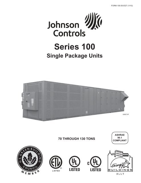
70 THROUGH 130 TONS<br />
FORM <strong>100</strong>.50-<strong>EG7</strong> (1110)<br />
00887VIP<br />
ASHRAE<br />
90.1<br />
COMPLIANT
Nomenclature<br />
2<br />
BASE MODEL NUMBER:<br />
YPAL070-105<br />
1 2 3 4 5 6 7 8 9 10 11 12 13 14 15 16<br />
BASE PRODUCT TYPE NOMINAL CAPACITY APPLICATION REFRIGERANT VOLTAGE SUPPLY RETURN DESIGN/SPECIAL<br />
Y : Johnson Controls 0 7 0 : 070-ton<br />
E : R410A 1 7 : 208/230-3-60 B : Bottom Supply F : Revision Level D (initial)<br />
P : <strong>Single</strong> <strong>Package</strong> 0 7 5 : 075-ton<br />
4 6 : 460 / 3 / 60 L : Left Supply X : Standard Product<br />
A : Air Cooled<br />
0 8 0 : 080-ton<br />
5 8 : 575 / 3 / 60<br />
R : Right Supply S : Special<br />
L : Scroll<br />
0 9 0 : 090-ton<br />
B : Bottom Return<br />
1 0 5 : 105-ton C : Cooling Only R : Rear Return<br />
N : Natural Gas Heat S : Side Return<br />
G : Natural Gas Heat SS HX<br />
M : Modulating Gas Heat<br />
E : Electric Heat<br />
H : Hot Water Heat<br />
S : Steam Heat<br />
C : Constant Volume<br />
V : VAV, VFD<br />
F : Flexsys<br />
YPAL120-130<br />
1 2 3 4 5 6 7 8 9 10 11 12 13 14 15 16<br />
BASE PRODUCT TYPE NOMINAL CAPACITY APPLICATION REFRIGERANT VOLTAGE SUPPLY RETURN DESIGN/SPECIAL<br />
Y : Johnson Controls 1 2 0 : 120-ton E : R-410 4 6 : 460 / 3 / 60 B : Bottom Supply F : Revision Level D (initial)<br />
P : <strong>Single</strong> <strong>Package</strong> 1 3 0 : 130-ton 5 8 : 575 / 3 / 60 L : Left Supply X : Standard Product<br />
A : Air Cooled<br />
R : Right Supply S : Special<br />
L : Scroll<br />
B : Bottom Return<br />
C : Cooling Only R : End Return<br />
M : Modulating Gas Heat<br />
E : Electric Heat<br />
H : Hot Water Heat<br />
S : Steam Heat<br />
N : Staged Gas Heat<br />
G<br />
: Staged SS Gas Heat<br />
FORM <strong>100</strong>.50-<strong>EG7</strong> (1110)<br />
C : Constant Volume<br />
V : VAV, VFD<br />
F : Flexsys<br />
JOHNSON CONTROLS
Table of Contents<br />
Nomenclature ..........................................................2<br />
Introduction ..............................................................4<br />
Features and Benefi ts .............................................5<br />
Application Data ....................................................12<br />
Physical Data ........................................................18<br />
Weight Data ...........................................................22<br />
Cooling Performance Data ....................................26<br />
Heating Performance Data – Gas/Electric Heat ....54<br />
Supply Fan Data ....................................................56<br />
Component Static Pressure Drops ........................58<br />
Gas Heat Pressure Drops .....................................62<br />
Electric Heat Pressure Drops ................................64<br />
Exhaust Fan Data ..................................................66<br />
Return Fan Data ....................................................68<br />
Electrical Data .......................................................70<br />
Controls .................................................................73<br />
Power Wiring .........................................................80<br />
Field Control Wiring ...............................................85<br />
General Arrangement Drawings ............................87<br />
Hot Water/Steam Coil Connection Locations ......108<br />
Lifting Lug Locations ...........................................109<br />
Power/Control Entry Drawing .............................. 110<br />
<strong>Guide</strong> Specifi cations ............................................ 111<br />
TABLES<br />
1 Supply Air Duct Connection Confi gurations ....13<br />
2 Return Air Duct Connection Confi gurations ....13<br />
3 Physical Data – Models 70-105 ......................18<br />
4 Physical Data – Models 120-130 ....................20<br />
5 Refrigerant Charge Data .................................21<br />
6 Effi ciency Ratings ...........................................21<br />
7 Approximate Base Operating Weights (lbs) ....22<br />
8 Component Weights (lbs) ...............................25<br />
9 Cooling Performance Data – 70 Ton Model ....26<br />
10 Cooling Performance Data – 75 Ton Model ....30<br />
11 Cooling Performance Data – 80 Ton Model ....34<br />
12 Cooling Performance Data – 90 Ton Model ....38<br />
13 Cooling Performance Data – 105 Ton Model ..42<br />
14 Cooling Performance Data – 120 Ton Model ..46<br />
15 Cooling Performance Data – 130 Ton Model ..50<br />
16 Gas Heat Performance Data ...........................54<br />
17 Electric Heat Performance Data .....................54<br />
18 28X25 Forward Curved Fan ............................56<br />
19 28X28 Forward Curved Fan ............................56<br />
20 32" Airfoil Fan ..................................................57<br />
21 40" Airfoil Fan ..................................................57<br />
22 Component Static Pressure Drops .................58<br />
JOHNSON CONTROLS<br />
FORM <strong>100</strong>.50-<strong>EG7</strong> (1110)<br />
23 Gas Heat Pressure Drops ...............................62<br />
24 Electric Heat Size Availability By Unit Size .....64<br />
25 Electric Heat Pressure Drops ..........................64<br />
26 Exhaust Fan Performance ..............................66<br />
27 18X18 Forward-Curved Fan ...........................66<br />
28 20X18 Forward-Curved Fan ...........................67<br />
29 32" Forward-Curved Fan ................................67<br />
30 Return Fan Performance ................................68<br />
31 270 SWSI Airfoil Fan .......................................68<br />
32 445 Plenum Fan ..............................................69<br />
33 Compressor Data – R410A .............................70<br />
34 Supply and Exhaust Fan Motor<br />
Electrical Data .................................................71<br />
35 Power Supply Voltage Limits ..........................71<br />
36 Condenser Fan Motors ...................................71<br />
37 Miscellaneous Electrical Data .........................72<br />
38 Electric Heat Amp Draw ..................................72<br />
39 Electrical Heat Stages .....................................72<br />
40 YPAL Supply Conductor Size Range<br />
70-75 Ton <strong>Units</strong> ...........................................79<br />
80 Ton <strong>Units</strong> ................................................79<br />
90-105 Ton <strong>Units</strong> .........................................79<br />
120-130 Ton <strong>Units</strong> .......................................79<br />
41 Fitting Location Dimensions ..........................108<br />
42 Lifting Lug Distances .....................................109<br />
43 Power/Control Dimensions ........................... 110<br />
FIGURES<br />
1 Traditional Overhead VAV Air Delivery<br />
System ............................................................14<br />
2 JOHNSON CONTROLS FlexSys Underfl oor Air<br />
Delivery System ..............................................14<br />
3 <strong>Single</strong>-Point Power Supply Wiring<br />
(YPAL120-130) ...............................................80<br />
4 <strong>Single</strong>-Point Power Supply Wiring with<br />
Non-Fused Disconnect (YPAL120-130) ..........81<br />
5 <strong>Single</strong>-Point Power Supply Wiring<br />
(YPAL070-105) ...............................................82<br />
6 <strong>Single</strong>-Point Power Supply Wiring with<br />
Non-Fused Disconnect (YPAL070-105) ..........83<br />
7 Dual Point Power Supply Wiring<br />
(YPAL070-105) ...............................................84<br />
8 Field Control Wiring ........................................85<br />
9 Field Control Wiring ........................................86<br />
10 General Arrangement Drawing .......................87<br />
11 Power/Control Entry Drawing ........................ 110<br />
3
Introduction<br />
The <strong>Series</strong> <strong>100</strong> single package<br />
units – Designed to meet the<br />
demands of the market for today<br />
and tomorrow.<br />
Better Economy...<br />
Lower total cost of ownership<br />
• High effi ciency <strong>Series</strong> <strong>100</strong> single package units are<br />
optimized for HFC-410a refrigerant. JOHNSON<br />
CONTROLS provides a standard product offering<br />
that meets the latest ASHRAE 90.1 energy<br />
effi ciency requirements.<br />
• Fully modulating gas heat and greater steps of capacity<br />
control offer superior off-design performance<br />
while maintaining optimum occupant comfort.<br />
• Accurate ventilation control ensures that no more<br />
than the proper amount of ventilation air is utilized.<br />
This avoids the energy cost of conditioning excess<br />
outside air and simultaneously monitors all other<br />
unit functions for maximized energy effi ciency.<br />
• Flexible design confi gurations simplify the design<br />
process and allows the <strong>Series</strong> <strong>100</strong> to be applied to<br />
virtually any building application.<br />
• Accessibility through double-wall access doors,<br />
spacious compartments and supportive fl oors improves<br />
serviceability.<br />
Better Ecology...<br />
Indoor air quality features for the indoor environment<br />
• A double-sloped stainless steel drain pan with a<br />
single drain connection ensures that all condensate<br />
is voided from the drain pan. It is also visible and<br />
accessible for periodic inspection and cleaning<br />
required by the ASHRAE 62 IAQ standard.<br />
• Double-wall construction of the roof, fl oor, doors,<br />
and walls prevents insulation fi bers from entering<br />
the conditioned air. The inner liner also facilitates<br />
periodic cleaning of the unit to prevent harmful<br />
build-up of bacteria or contaminants.<br />
• The single package unit control center uses microprocessor<br />
logic to analyze and optimize ventilation<br />
decisions and perform demand ventilation, airfl ow<br />
compensation, and airfl ow measurement to maintain<br />
the air quality at a healthy level.<br />
4<br />
FORM <strong>100</strong>.50-<strong>EG7</strong> (1110)<br />
LD07431<br />
The <strong>Single</strong> <strong>Package</strong> Unit Control Center uses microprocessor logic<br />
to optimize operation of the <strong>Series</strong> <strong>100</strong> single package unit.<br />
JOHNSON CONTROLS
Features and Benefi ts<br />
AIRFLOW CONFIGURATIONS<br />
Variable-Air-Volume – <strong>Series</strong> <strong>100</strong> units are available<br />
for single-zone variable-air-volume (VAV) applications.<br />
Control can be used with a zone sensor or building automation<br />
system. Supply fans are controlled to the supply<br />
duct static pressure setpoint, which can be reset via a<br />
BAS, or through a 0-5VDC analog input on the unit<br />
controller for optimized duct static pressure control. The<br />
static pressure transducer is provided in the single package<br />
unit, and 5/16" or 1/4" plastic tubing and static pressure<br />
sensor must be supplied by others and installed<br />
approximately 3/4 down the longest duct run.<br />
FlexSys Underfl oor Air VAV – <strong>Series</strong> <strong>100</strong> units are<br />
confi gurable for underfl oor air variable-air-volume (VAV)<br />
applications. Control can be used with a zone sensor or<br />
building automation system. Supply fans are controlled<br />
to the supply duct static pressure setpoint, which can<br />
be reset via a BAS, or through a 0-5VDC analog input<br />
on the unit controller for optimized duct static pressure<br />
control. The static pressure transducer is provided in<br />
the single package unit, and 5/16" or 1/4" plastic tubing<br />
and static pressure sensor must be supplied by others<br />
and installed approximately 3/4 down the longest duct<br />
run. Refer to engineering guide form <strong>100</strong>.50-EG8 for<br />
more detailed information on this application.<br />
Constant Volume – <strong>Series</strong> <strong>100</strong> units are available for<br />
single-zone constant volume applications. Control can<br />
be used with a zone sensor, thermostat, or building<br />
automation system.<br />
COOLING AND HEATING CONFIGURATIONS<br />
Cooling Only – For applications where no heat is<br />
required, or heating is provided elsewhere within the<br />
building HVAC system, cooling only units include an<br />
empty discharge plenum. Supply duct connections<br />
are confi gurable for bottom, left or right discharge.<br />
The supply air temperature sensor is included and<br />
factory-installed.<br />
Staged Gas Heat – For applications requiring gas heat<br />
for morning warm-up, or other heating needs, a staged<br />
natural gas furnace is available. The furnace is located<br />
in the discharge plenum, downstream of the supply fan.<br />
The supply air temperature sensor is located across the<br />
face of the supply duct opening in the unit. Furnaces<br />
are designed in 375 mbh modules with two stages in<br />
each. Three stages are available for the YPAL070-130.<br />
For 70 through 105 ton units, optional Propane Conversion<br />
Kits contain the necessary orifi ces and gas valve/<br />
parts to convert staged heat only (Not modulating) from<br />
natural gas to propane. Ignition and safety controls are<br />
included and factory-wired. <strong>Units</strong> with staged gas heat<br />
are UL listed.<br />
JOHNSON CONTROLS<br />
FORM <strong>100</strong>.50-<strong>EG7</strong> (1110)<br />
Modulating Gas Heat – For applications requiring<br />
gas heat for morning warm-up, supply air tempering or<br />
other heating needs, a modulating natural gas furnace<br />
is available for fi ner temperature control. The furnace<br />
is located in the discharge plenum, downstream of<br />
the supply fan. The supply air temperature sensor is<br />
located across the face of the supply duct opening in<br />
the unit. Furnaces are designed in 375 mbh modules<br />
in 8:1 turndown increments. Three are available for the<br />
YPAL070-130 (8:1, 16:1 or 24:1 turndown). Ignition and<br />
safety controls are included and factory-wired. <strong>Units</strong><br />
with modulating gas heat are UL listed.<br />
Electric Resistance Heat – For applications where<br />
electric heat is desired, a slip-in electric resistance<br />
heat element is available in sizes from 80-250 kW<br />
depending on the single package unit model size. The<br />
number of stages varies by size and voltage, but all<br />
have a minimum of two stages of capacity. <strong>Units</strong> with<br />
electric heat are ETL listed.<br />
Hot Water Heat – For applications where hot water is<br />
available for heating, a hot water heating coil is available.<br />
A range of coil fi n count selections are available to<br />
properly size the heating for the application. <strong>Units</strong> with<br />
hot water heat are ETL listed.<br />
Steam Heat – For applications where steam is available<br />
for heating, a steam heating coil is available. A range<br />
of coil fi n count selections are available to properly size<br />
the heating for the application. <strong>Units</strong> with steam heat<br />
are ETL listed.<br />
POWER OPTIONS<br />
<strong>Single</strong>-point supply with terminal block – This<br />
confi guration is standard, and includes three terminals<br />
for the incoming 3-phase power and is the standard<br />
confi guration for the <strong>Series</strong> <strong>100</strong> product. It includes the<br />
enclosure, terminal-block, and interconnecting wiring to<br />
the compressors, heater and furnace controls, all fans,<br />
etc. In this confi guration, code requires that a means of<br />
disconnect (not provided) must be installed at the site<br />
within line-of-sight of the equipment.<br />
<strong>Single</strong>-point supply with non-fused disconnect<br />
switch – This option is the same the single-point with<br />
terminal block option except it includes a unit-mounted<br />
through-the-door manual non-fused disconnect switch<br />
with an external, lockable handle (in compliance with<br />
Article 440-14 of N.E.C.). This option provides a means<br />
to isolate the unit power voltage for servicing. Others<br />
must supply separate external fusing which must comply<br />
with the National Electric Code and/or local codes.<br />
5
Features and Benefi ts (continued)<br />
Dual-point supply with terminal block – This option<br />
includes enclosure, terminal blocks circuited to the supply<br />
and exhaust fans and control transformer and a second<br />
set of terminal blocks with interconnecting wiring to<br />
the compressors, heat (if applicable) and condenser.<br />
Convenience Outlet – This options includes a<br />
powered 115V GFCI convenience outlet that can be<br />
used for powering tools or lights for servicing. A protective<br />
cover plate is included while not in use. The<br />
outlet is located on the bottom left hand corner of the<br />
power panel.<br />
CONTROL FEATURES AND OPTIONS<br />
Microprocessor-Based <strong>Single</strong> <strong>Package</strong> Unit Controller<br />
– All <strong>Series</strong> <strong>100</strong> units are equipped with a factoryinstalled,<br />
programmed and commissioned unit controller<br />
with all I/O capabilities and control sequences. The controls<br />
include all on-board diagnostic, safety and control<br />
features to operate the single package unit. A multimedia<br />
card interface is included for software upgrades and can<br />
be used for data logging to simplify equipment troubleshooting.<br />
Communication ports are included as standard<br />
with three alarm outputs, a shutdown contact, remote<br />
start/stop input, smoke ventilation controls, analog inputs<br />
for supply air temperature and duct static pressure rest,<br />
along with a variety of other capabilities.<br />
Standard Ambient – YPAL070-105 models operate<br />
down to 45°F as standard. YPAL120-130 models operate<br />
down to 0°F as standard.<br />
Low Ambient – (YPAL070-105) This option includes<br />
low ambient control of the fi rst refrigerant circuit down<br />
to 0°F through the use of suction and discharge pressure<br />
transducers on circuit one, and condenser fan<br />
speed using a variable-frequency drive on the fi rst<br />
condenser fan of circuit one. Mechanical cooling<br />
with circuit and three for YPAL070-105 is locked out<br />
below 45°F.<br />
Low Ambient on Circuits One, Two and Three –<br />
(YPAL070-105) This option includes low ambient control<br />
of the fi rst, second and third refrigerant circuits down to<br />
0°F through the use of suction and discharge pressure<br />
transducers on both circuits.<br />
Pressure Transducers with Readout Capability –<br />
This option includes suction and discharge pressure<br />
transducers on each circuit and provides pressure<br />
readout of all circuits at the unit control panel.<br />
6<br />
FORM <strong>100</strong>.50-<strong>EG7</strong> (1110)<br />
SENSOR AND THERMOSTAT AND SENSOR<br />
OPTIONS<br />
Wall-Mount Zone Sensor –<br />
a 10 kOhm thermister type<br />
III NTC zone sensor for wall<br />
mounting. This zone sensor<br />
is for sensing temperature<br />
only, and does not include<br />
any setpoint adjustment features.<br />
7-Wire Thermostat – This<br />
option is for a ship-loose thermostat<br />
to interface with the<br />
<strong>Series</strong> <strong>100</strong> unit. All models,<br />
YPAL070-130, include an interface<br />
for a 7-wire thermostat<br />
as standard.<br />
COMMUNICATIONS<br />
Zone Sensor<br />
Thermostat<br />
BACnet MSTP (RS-485) Communications – This<br />
communication option is standard on every <strong>Series</strong> <strong>100</strong><br />
unit. Communications to the unit are through a twisted<br />
pair, and the wire terminations are on the primary unit<br />
control board. See supplemental information for the<br />
available control points and PICS/Bibbs statements<br />
of conformity.<br />
Modbus RTU Communications – This communication<br />
option is standard on every <strong>Series</strong> <strong>100</strong> unit and can be<br />
used in lieu of the BACnet communications (only one<br />
can be used at a time). See supplemental information<br />
for the available control points.<br />
JOHNSON CONTROLS
FILTER OPTIONS<br />
Filter Options – two-inch throwaway, cleanable,<br />
carbon coated or pleated fi lters in an angled rack are<br />
available. For higher fi ltration requirements, optional<br />
rigid fi lter racks are available with twelve-inch 65%<br />
or 95% effi cient rigid fi lters. Two-inch pre-fi lters are<br />
included with rigid fi lter options. The rigid fi lter rack option<br />
is available without fi lter media where fi eld-supplied<br />
fi lters are required.<br />
OUTSIDE AIR DAMPER OPTIONS<br />
Manual Damper – This option includes a manually<br />
adjustable outside air damper. It is manually adjustable<br />
at the unit by setting a mechanical stop between<br />
0-<strong>100</strong> percent.<br />
Two-Position – This outside air damper option is controlled<br />
to a two positions, opened and closed. Determination<br />
of the damper position is based on the occupancy<br />
schedule. In the occupied mode, the outside air<br />
damper is positioned to the manually confi gured point<br />
(set by mechanical stop). In the unoccupied mode, the<br />
damper is fully closed.<br />
Modulating Economizer – This option includes<br />
modulating outdoor air and return air dampers that are<br />
software interlocked (YPAL070-130 software interlock)<br />
and positioned by fully modulating, solid state damper<br />
actuators. Control of the damper is via a standard ambient<br />
outdoor air dry bulb sensor, or optional single or<br />
comparative enthalpy controls.<br />
Airfl ow Measurement – Optional outside airfl ow measurement<br />
is available on units equipped with a Modulating<br />
Economizer. Two options exist for airfl ow measurement;<br />
minimum (0-25%) and full (0-<strong>100</strong>%) .<br />
CO Sensors – Optional carbon dioxide sensors for<br />
2<br />
occupied space that operate demand ventilation control<br />
opening outside air dampers to ventilate building. The<br />
CO sensors can operate in a single or comparative<br />
2<br />
control scheme.<br />
Rain Hoods on Outside Air Intakes – For all options<br />
with outside air intake openings, rain hoods are provided<br />
as standard to keep moisture from entering the equipment.<br />
The rain hoods are an integral part of the unit<br />
and are rotated into place at the jobsite.<br />
RELIEF SYSTEM<br />
Barometric Relief – Optional building air exhaust shall<br />
be accomplished through barometric relief dampers installed<br />
in the return air plenum. The dampers will open<br />
relative to the building pressure. The opening pressure<br />
shall be adjustable via a spring tension adjustment.<br />
JOHNSON CONTROLS<br />
FORM <strong>100</strong>.50-<strong>EG7</strong> (1110)<br />
On/Off Powered Exhaust – This option provides simple<br />
building pressure control. It can be controlled via a building<br />
pressure signal, or via outside air damper control.<br />
This option is not available for VAV units.<br />
Modulating Powered Exhaust with Damper Control<br />
– This option consists of a constant-speed exhaust fan<br />
with a discharge damper that is modulated to control the<br />
fl ow of exhaust air. The damper control logic is based<br />
on the building static pressure setpoint within the single<br />
package unit controller. The static pressure transducer<br />
is provided in the return plenum of the single package<br />
unit, and 5/16" or 1/4" plastic tubing and static pressure<br />
sensor must be supplied by others and installed in a<br />
representative location in the building.<br />
Modulating Powered Exhaust with a VFD – This option<br />
consists of a VFD to modulate the speed of the exhaust<br />
fan to control the fl ow of exhaust air. The VFD control<br />
logic is based on the building static pressure setpoint<br />
within the single package unit controller. The static pressure<br />
transducer is provided in the return plenum of the<br />
single package unit, and 5/16" or 1/4" plastic tubing and<br />
static pressure sensor must be supplied by others and<br />
installed in a representative location in the building.<br />
Powered Return Fan with Exhaust – This option<br />
uses SWSI plenum fan(s) to control building pressure.<br />
The fan motors are driven by a VFD to maintain a constant<br />
return plenum pressure. An exhaust hood with a<br />
modulating control damper is used to maintain building<br />
pressure via the building static pressure. The static<br />
pressure transducer is provided in the return plenum of<br />
the single package unit, and 5/16" or 1/4" plastic tubing<br />
and static pressure sensor must be supplied by others<br />
and installed in a representative location in the building.<br />
The powered return fan is also available without the<br />
exhaust capabilities. For units with no exhaust capabilities,<br />
the HVAC system must provide alternate means of<br />
controlling building pressure.<br />
SUPPLY FAN OPTIONS<br />
DWDI Forward-Curved Supply Fan – The standard<br />
supply air blower in the YPAL070-105 models is a<br />
forward-curved supply fan. This fan is good for medium<br />
static pressures and high airfl ows.<br />
DWDI Airfoil Supply Fan – An optional airfoil blade<br />
supply fan is available on all models for higher static<br />
conditions. This option offers higher effi ciency and lower<br />
sound in certain applications.<br />
Fan Skid Isolation – the entire supply fan assembly<br />
is isolated from the unit base with two-inch defl ection<br />
springs, or one (standard) or two-inch defl ection springs<br />
with seismic restraints.<br />
7
Features and Benefi ts (continued)<br />
Supply and Exhaust Fan Motors – high effi ciency<br />
ODP, and standard and high effi ciency TEFC motors<br />
are available all meeting the Energy Policy Act of 1992<br />
(EPACT).<br />
Supply Fan VFD and Manual Bypass – for VAV applications,<br />
VFD’s are provided to modulate air fl ow.<br />
Optional manual bypass can also be provided to allow<br />
full airfl ow in the event of a VFD failure.<br />
EVAPORATOR SECTION<br />
Double Sloped Stainless Steel Drain Pan – The <strong>Series</strong><br />
<strong>100</strong>’s stainless steel drain pan is factory-mounted<br />
and installed on every unit. A condensate drain trap is<br />
needed, and must be provided and installed in the fi eld<br />
by others.<br />
Double Wall Construction – Double-wall construction<br />
is the standard construction of the <strong>Series</strong> <strong>100</strong> and incorporates<br />
powder coated pre-fabricated outer panels and<br />
corner post for maximum exterior surface protection.<br />
Factory Shrink-wrap – All <strong>Series</strong> <strong>100</strong> single package<br />
units are shipped from the factory with factory-fresh<br />
shrink-wrap packaging. No longer does the contractor<br />
need to worry about dirt and debris clogging up condenser<br />
coils or moisture leaking into the air handler on<br />
the units way to the job site or rigging yard.<br />
Copper Fins – For more extreme climates that aggressively<br />
can attack aluminum, copper tube evaporator coils<br />
with copper fi ns are available. (This is not recommended<br />
for units in areas where they may be exposed to acid<br />
rain or environments where ammonia is present)<br />
CONDENSER FEATURES AND OPTIONS<br />
Scroll Compressors – Reliable, effi cient, trouble-free<br />
operation is the true measure of a single package unit’s<br />
value. That’s why JOHNSON CONTROLS <strong>Series</strong> <strong>100</strong><br />
<strong>Package</strong>d <strong>Single</strong> package units Air Conditioners use<br />
established scroll compressor technology to deliver<br />
dependable, economical performance in a wide range of<br />
applications. With the <strong>Series</strong> <strong>100</strong> <strong>Single</strong> package units,<br />
you get the latest generation of compressor enhancements<br />
added to the scroll’s inherent strengths. The<br />
8<br />
Drain Pan Detail*<br />
LD08022<br />
*NOTE:<br />
This is a visual reference only. Actual drain pan pitch will vary.<br />
FORM <strong>100</strong>.50-<strong>EG7</strong> (1110)<br />
simplicity of a hermetic scroll compressor allows the use<br />
of fewer moving parts to minimize breakdown.<br />
Multiple Compressor Staging – Through the use of<br />
the scroll compressor, the <strong>Series</strong> <strong>100</strong> has the ability<br />
to stage it’s cooling by enabling and disabling multiple<br />
single stage compressors on multiple circuits.<br />
These compressors are manifolded together in pairs on<br />
a single refrigeration circuit have 3 refrigeration circuits<br />
operating a dual manifolded scroll compressor set.<br />
Compressor Circuiting – the <strong>Series</strong> <strong>100</strong> is designed<br />
so that only 2 scroll compressors are in tandem within<br />
one refrigeration circuit. This means more reliable compressors,<br />
and less equipment down time. With multiple<br />
circuits, if a compressor should ever fail on one circuit,<br />
the other circuit/s will remain operational to work to<br />
maintain occupied loads. The <strong>Series</strong> <strong>100</strong> system has 3<br />
circuits in a unit.<br />
Condenser Fan Motors – The condenser fan motors<br />
used on the <strong>Series</strong> <strong>100</strong> unit are Totally Enclosed Air<br />
Over (TEAO) to provide maximum durability through<br />
any season.<br />
Hot Gas Bypass – This options permits continuous,<br />
stable operation at capacities below the minimum step<br />
of unloading by introducing an artifi cial load on the<br />
evaporator. For models YPAL070-105, it is used on the<br />
lead circuit. For models YPAL120-130 it is available on<br />
the fi rst, or all circuits.<br />
Replaceable Core Suction Line Driers – suction line<br />
driers are standard on the <strong>Series</strong> <strong>100</strong> single package<br />
unit. An option is provided for replaceable core driers<br />
(standard on YPAL120-130)<br />
Copper Fins – For more extreme climates that aggressively<br />
can attack aluminum, copper tube condenser coils<br />
with copper fi ns are available. (This is not recommended<br />
for units in areas where they may be exposed to acid<br />
rain or environments where ammonia is present. YPAL<br />
120-130 only.)<br />
Pre-Coated Fins – an epoxy-coated aluminum fi n stock<br />
to guard from corrosive agents and insulate against<br />
galvanic potential. Recommended for mild seashore or<br />
industrial locations (on 120-130 ton units only).<br />
Post-Coated Fins – Technicoat coil-coating process<br />
used on condenser coils for seashore and other corrosive<br />
applications (with the exception of strong alkalis,<br />
oxidizers, wet bromide, chlorine and fl uorine in concentrations<br />
greater than <strong>100</strong>ppm).<br />
Compressor Sound Blankets – Optional compressor<br />
acoustic sound blankets are available for sound sensitive<br />
applications.<br />
JOHNSON CONTROLS
ROOF CURBS<br />
Full perimeter roof curbs – This option includes a<br />
knock-down 14" high roof curb for use with wood nailer<br />
(by others). Roof curb supports the entire perimeter of<br />
the unit.<br />
Partial perimeter roof curbs – This option includes a<br />
knock-down 14" high roof curb for use with wood nailer<br />
(by others). Roof curb supports the air handling section<br />
with a separate support under the condenser end.<br />
CABINET FEATURES AND OPTIONS<br />
Double-Wall Access Doors - Full-sized access doors<br />
provide easy access into the unit for routine maintenance<br />
and inspection. Solid wall liners encase insulation and<br />
prevent damage and erosion into the airstream.<br />
Diffuser Section – An optional diffuser section is available<br />
downstream of the supply fan in the extended<br />
discharge plenum cabinet option. The diffuser section<br />
distributes the airfl ow from the fan evenly across<br />
the downstream fi lter bank to optimize fi lter life and<br />
JOHNSON CONTROLS<br />
FORM <strong>100</strong>.50-<strong>EG7</strong> (1110)<br />
effectiveness. The diffuser design is optimized to provide<br />
uniform fl ow at minimal airside pressure loss.<br />
Downstream Final Filter Rack – A 90-95% effi cient<br />
twelve-inch rigid fi lter rack and fi lters shall be provided<br />
downstream of the supply fan and diffuser segment for<br />
hospital applications (YPAL070-105 only). A magnahelic<br />
pressure gauge is included and visible from the outside<br />
of the unit for servicing and code compliance.<br />
Blank Section – A blank section shall be provided<br />
downstream of the supply fan and diffuser section.<br />
ACCESSORIES<br />
Filter Switch – An optional dirty fi lter alarm can be provided<br />
that will provide an alarm when the fi lters require<br />
cleaning.<br />
Magnahelic Filter Pressure Gauge – On units<br />
equipped with downstream fi ltration, a magnahelic fi lter<br />
gauge is included and visible on the exterior of the unit.<br />
The fi lter gauge measures the air pressure drop for<br />
through the rigid fi lter bank to indicate when replacement<br />
is required.<br />
9
Features and Benefi ts (continued)<br />
YPAL070-105 MODEL<br />
10<br />
Angled<br />
evaporator<br />
coil for<br />
lower<br />
face<br />
velocities<br />
00567VIP<br />
Factoryinstalled<br />
single package<br />
unit controller<br />
V-banked<br />
condenser<br />
coils to<br />
protect<br />
from hail<br />
damage<br />
Complete<br />
double-wall<br />
construction<br />
of walls,<br />
fl oors,<br />
ceiling,<br />
and panels<br />
Double-sloped<br />
stainless steel<br />
IAq drain<br />
pan and<br />
intermediate<br />
drain pan<br />
Doors on both<br />
sides of unit<br />
and tie backs<br />
for unit<br />
servicing<br />
Centrifugal<br />
fan powered<br />
exhaust fan or<br />
optional plenum<br />
return fan<br />
Optional<br />
replaceable<br />
core fi lter<br />
driers<br />
Condenser<br />
wire screen<br />
Optional louvers<br />
available<br />
Optional<br />
horizontal<br />
supply air<br />
openings<br />
Distributor<br />
tubes<br />
protected<br />
in plastic<br />
sleeves<br />
Angled or<br />
rigid fl at<br />
fi lter<br />
section<br />
Optional<br />
airfl ow<br />
measurement<br />
station<br />
Rainhoods to<br />
prevent<br />
moisture<br />
from entering<br />
the unit<br />
FORM <strong>100</strong>.50-<strong>EG7</strong> (1110)<br />
JOHNSON CONTROLS
YPAL120-130 MODEL<br />
• Integrated JOHNSON CONTROLS ISNConneXsys control solution<br />
• Standard BACnet MS/TP and Modbus communications<br />
Advanced <strong>Single</strong> <strong>Package</strong> <strong>Units</strong> Controller<br />
• Multimedia card for updates (no EPROM)<br />
• Multimedia card used for data logging<br />
• Fast and easy setup<br />
JOHNSON CONTROLS<br />
Collapsible OA hoods<br />
• Collapsible for shipping to reduce freight<br />
• <strong>Single</strong>-piece shipment<br />
24:1 modulating gas heat<br />
• Induced draft furnace<br />
• Accepts gas pressures down to 3.5"<br />
• 6-stage base design<br />
Shared-Fan Design<br />
• Standard low-ambient to 0°F<br />
• Control to discharge pressure<br />
• Quiet part load operation<br />
FORM <strong>100</strong>.50-<strong>EG7</strong> (1110)<br />
Exhaust & return fans<br />
• Horizontal return for all confi gurations<br />
• DWDI centrifugal exhaust fans<br />
• SWSI plenum return fans<br />
• Variable-frequency drive options<br />
• Standard Stainless steel<br />
drain pan<br />
Mixing box<br />
• OA from two sides<br />
• Facilitates mixing<br />
Side discharge with heat<br />
• Does not require an elevated structure or curb<br />
• Flexible solution for building application<br />
Evaporator<br />
• Angled coil to reduce<br />
risk of carryover<br />
<strong>Single</strong> supply fan<br />
• Eliminates stratifi cation<br />
• Fewer moving parts<br />
• Solid steel shaft<br />
• Isolated assembly<br />
• Laser aligned and balanced<br />
Blower VFDs<br />
• Located in conditioned space<br />
• Remote keypad in control section<br />
• In fi ltered air stream to prevent dust and<br />
dirt build-up<br />
11
Application Data<br />
GENERAL<br />
The <strong>Series</strong> <strong>100</strong> air conditioning units are designed for<br />
outdoor installation. When selecting a site for installation,<br />
be guided by the following conditions:<br />
• Unit must be installed on a level surface.<br />
• For the outdoor location of the unit, select a place<br />
having a minimum sun exposure and an adequate<br />
supply of fresh air for the condenser.<br />
• Also avoid locations beneath windows or between<br />
structures.<br />
• Optional condenser coil protection should be used<br />
for seashore locations or other harsh environments.<br />
• The unit should be installed on a roof that is structurally<br />
strong enough to support the weight of the<br />
unit with a minimum of defl ection. It is recommended<br />
that the unit(s) be installed not more than<br />
15 feet from a main support beam to provide proper<br />
structural support and to minimize the transmission<br />
of sound and vibration. Ideally, the center of gravity<br />
should be located over a structural support or<br />
building column.<br />
• Location of unit(s) should also be away from building<br />
fl ue stacks or exhaust ventilators to prevent possible<br />
reintroduction of contaminated air through the<br />
outside air intakes.<br />
• Be sure the supporting structures will not obstruct<br />
the duct, gas or wiring connections.<br />
• Proper service clearance space of 6-feet around<br />
the perimeter of the unit, 8-feet on one side for coil<br />
servicing, and 12-feet to any adjacent units is required<br />
to eliminate cross contamination of exhaust<br />
and outdoor air, and for maintenance tasks such<br />
as coil pull and cleaning. No obstructions should<br />
be above the condensing unit section.<br />
LOCATION<br />
Of the many factors that can effect the location of<br />
equipment, some of the most important to consider are<br />
Structural, Acoustical and Service clearances. Proper<br />
attention should be made at the design stage to ensure<br />
proper structural support. In cases where equipment is<br />
being replaced, be aware of building design to insure<br />
support is adequate for the application.<br />
The next most important consideration in applying single<br />
package units equipment is that of sound from the<br />
equipment. Special care should be made to keep the<br />
single package unit away from sound sensitive areas<br />
such as conference rooms, auditoriums and executive<br />
offi ces and any other room that may have potential for<br />
tenant occupancy. Possible locations could be above<br />
hallways, mechanical or utility rooms.<br />
12<br />
FORM <strong>100</strong>.50-<strong>EG7</strong> (1110)<br />
Finally, service clearances should be maintained in<br />
single package unit design to insure safe access to the<br />
unit. Unit clearances are designed so that technicians<br />
have enough space between units, building walls, and<br />
edges of building to gain access safely. In cases where<br />
space is limited, please call your local JOHNSON CON-<br />
TROLS representative for additional information.<br />
96"<br />
LD08044<br />
NOTE:<br />
1. Under certain conditions these clearances may be encroached upon.<br />
2. This is a visual reference for all <strong>Series</strong> <strong>100</strong> units.<br />
RIGGING<br />
Proper rigging and handling of the equipment is mandatory<br />
during unloading and setting it into position to<br />
retain warranty status.<br />
Spreader bars must be used by cranes to prevent damage<br />
to the unit casing. All lifting lugs must be used when<br />
lifting the single package unit unit. Fork lifts will damage<br />
the single package unit and are not recommended.<br />
Care must be taken to keep the unit in the upright position<br />
during rigging and to prevent damage to the watertight<br />
seams in the unit casing. Avoid unnecessary jarring<br />
or rough handling.<br />
UNIT PLACEMENT<br />
• Elevated – Elevated roof curbs or dunnage steel<br />
can be used to support the unit in order to raise it<br />
to specifi c heights. When this type of placement<br />
is required, be sure to keep unit access in mind.<br />
Cat walks or other forms of unit access may be<br />
required to one or both sides of the unit, depending<br />
on your area of the country and the local codes<br />
that are enforced. Please check with local offi cials<br />
to ensure the application conforms to local codes<br />
and regulations.<br />
• Ground Level Locations – It is important that the<br />
units be installed on a substantial base that will not<br />
settle, causing strain on the refrigerant lines and<br />
sheet metal and resulting in possible leaks. A onepiece<br />
concrete slab with footers extended below<br />
the frost line is highly recommended. Additionally,<br />
the slab should be isolated from the main building<br />
foundation to prevent noise and vibration transmission<br />
to the building structure.<br />
JOHNSON CONTROLS
For ground level installations, precautions should be<br />
taken to protect the unit from tampering by, or injury<br />
to, unauthorized persons. Erecting a fence around<br />
the unit is common practice.<br />
• Roof curb – JOHNSON CONTROLS offers optional<br />
roof curbs designed specifi cally for the <strong>Series</strong> <strong>100</strong><br />
footprint. These curbs come in full perimeter or<br />
open condenser models and are shipped disassembled<br />
and require fi eld assembly and installation.<br />
For bottom supply and return openings, the curbs<br />
have matching connections to ease installation. A<br />
pipe chase that matches the single package unit<br />
pipe chase is also included in the curb footprint for<br />
through-the-curb utility connections.<br />
The curb should be located according to the location<br />
recommendations above, and properly sealed<br />
to prevent moisture and air leakage into and out of<br />
the duct system. Flexible collars should be used<br />
when connecting the duct work to prevent unit noise<br />
transmission and vibration into the building.<br />
Duct work should be supported independently of<br />
the unit.<br />
TABLE 1: SUPPLY AIR DUCT CONNECTION CONFIGURATIONS<br />
Unit Confi guration<br />
Standard Cabinet<br />
Supply Air<br />
Bottom Left Right<br />
Cooling only X X X<br />
Cool/gas heat X X<br />
YPAL Cool/electric heat X<br />
070-105 Cool/hydronic heat<br />
Extended Cabinet<br />
X<br />
Cooling only X X X<br />
Cool/hydronic heat<br />
Standard Cabinet<br />
X X X<br />
YPAL Cooling only X X X<br />
120-130 Cool/electric heat X<br />
Cool/gas heat X X<br />
JOHNSON CONTROLS<br />
UNIT ORIENTATION<br />
FORM <strong>100</strong>.50-<strong>EG7</strong> (1110)<br />
TABLE 2: RETURN AIR DUCT CONNECTION CONFIGURATIONS<br />
Unit Confi guration<br />
Bottom<br />
Return Air<br />
Left Right Front<br />
No exhaust X X X X<br />
YPAL Barometric relief damper X X X<br />
070-105 Powered exhaust fan<br />
(all types) X X X<br />
Powered return fan X<br />
No exhaust X X<br />
YPAL Barometric relief damper X X<br />
120-130 Powered exhaust fan<br />
(all types) X X<br />
Powered return fan X X<br />
For applications with multiple single package units<br />
located in close proximity on the roof, the orientation<br />
of the unit may be important to reduce the potential for<br />
re-entrainment of outside airfl ow. Regardless of the<br />
outside air and exhaust air openings on a unit, all single<br />
package unit applications can permit recirculation of<br />
exhaust air to the return, if applied improperly.<br />
HORIZONTAL APPLICATIONS<br />
The spectrum of applications for single package units in<br />
today’s market is continuing to grow wider by the day.<br />
Flexibility in unit design and construction is a must in<br />
today’s market in order to insure safe and sound applications<br />
of HVAC equipment. The <strong>Series</strong> <strong>100</strong> has been<br />
designed for specifi c application of horizontal supply<br />
and return airfl ow taking the guess work out if unit application<br />
by building a unit specifi c to these needs. If<br />
the application calls for horizontal supply and return air,<br />
JOHNSON CONTROLS can ship it from the factory as<br />
a horizontal unit. This option elevates the need for fi eld<br />
modifi cation of equipment saving time and money. The<br />
<strong>Series</strong> <strong>100</strong> can support a left discharge on all units and/<br />
or right discharge on all cooling only units and hydronic<br />
heat units with an extended cabinet. Return air can be<br />
brought through the end or side return air inlet making<br />
the unit specifi c to building needs.<br />
NOTE:<br />
This diagram is provided as a visual reference of the <strong>Series</strong> <strong>100</strong> discharge & return air openings & locations for all sizes. Please refer to the dimensional<br />
data for exact size & location of panels and openings.<br />
LD08045<br />
13
Application Data (continued)<br />
ECONOMIZER<br />
The economizer section is used for ventilation of the<br />
conditioned space to maintain indoor air quality, and<br />
also to reduce energy consumption by using outdoor<br />
air cooling in lieu of mechanical cooling. If outdoor air is<br />
appropriate for cooling, but not suffi cient for the cooling<br />
demand, mechanical cooling will stage on as necessary<br />
until the cooling load is met.<br />
Dual (comparative or differential) enthalpy operation is<br />
the most accurate and effi cient means of economizer<br />
operation. The IPU controller monitors the return and<br />
outside air energy content, and selects the lower of the<br />
two for operation.<br />
VAV SUPPLY AIR PRESSURE CONTROL<br />
Traditional packaged single package unit systems<br />
use inlet guide vanes (IGVs) for duct static pressure<br />
control. These control supply duct pressure by modulating<br />
dampers (introducing losses and ineffi ciencies)<br />
on the inlet of the fan, open and closed. JOHNSON<br />
CONTROLS variable frequency drives (VFDs) offer<br />
superior fan speed control and quieter, energy effi cient<br />
operation.<br />
FIG 1: TRADITIONAL OVERHEAD VAV AIR<br />
DELIVERY SYSTEM<br />
For VAV applications, the JOHNSON CONTROLS <strong>Series</strong><br />
<strong>100</strong> unit uses a VFD to modulate fan speed and<br />
maintain a constant duct static pressure. VFDs offer<br />
superior control over the operation of the unit at part<br />
load, and offer the additional benefi ts of quieter and<br />
more effi cient operation when compared to IGV.<br />
FLEXSYS<br />
The traditional approach to HVAC design in commercial<br />
buildings has been to supply conditioned air through<br />
14<br />
FORM <strong>100</strong>.50-<strong>EG7</strong> (1110)<br />
extensive overhead duct networks to an array of diffusers<br />
spaced evenly in the ceiling. In Figure 1, the conditioned<br />
air is both supplied and returned at ceiling level. Ceiling<br />
plenums must be designed large enough to accommodate<br />
the supply ducts that run through them. Return air<br />
is typically confi gured as ceiling plenum return without<br />
any ductwork. This type of air distribution, known as the<br />
“well-mixed” type, is the most common system in use.<br />
This conventional HVAC system is designed to promote<br />
complete mixing of supply air with room air, thereby<br />
maintaining the entire volume of all air in the space (from<br />
fl oor to ceiling) at the desired space setpoint temperature.<br />
In addition, to meet IAQ requirements, an adequate<br />
supply of fresh outside air must be introduced to this mix.<br />
A key disadvantage to this control strategy is that it has<br />
no provisions to accommodate different temperature<br />
preferences among the building occupants or to provide<br />
preferential ventilation in the occupied zone.<br />
FIG. 2: JOHNSON CONTROLS FLEXSYS UNDER-<br />
FLOOR AIR DELIVERY SYSTEM<br />
With the JOHNSON CONTROLS FlexSys Underfl oor<br />
Air System, conditioned air from the air handling unit<br />
(AHU) is ducted to the underfl oor plenum. As shown in<br />
Figure 2, this conditioned air fl ows freely throughout<br />
the plenum to individual supply discharge outlets. Unlike<br />
the larger single supply duct outlets typical of overhead<br />
systems, underfl oor systems are confi gured to<br />
have a large number of smaller supply outlets, in close<br />
proximity to the building occupants. These adjustable<br />
outlets provide an opportunity for nearby occupants to<br />
have some amount of control over thermal comfort<br />
conditions in their local environment. Air is returned from<br />
the room at ceiling level (unducted plenum return is<br />
shown). The resulting overall fl oor-to-ceiling air fl ow<br />
pattern takes advantage of the natural buoyancy produced<br />
by heat sources in the space and more effi -<br />
ciently removes heat loads and contaminants from the<br />
space, particularly for cooling applications. In fact, some<br />
of the most important advantages of underfl oor systems<br />
JOHNSON CONTROLS
over ceiling-based systems occur during cooling conditions,<br />
which are required year-round in the vast majority<br />
of interior offi ce space in many parts of the United<br />
States.<br />
HARSH ENVIRONMENTS – CONDENSER AND<br />
EVAPORATOR COIL PROTECTION<br />
For harsh environmental conditions such as seashore<br />
applications, JOHNSON CONTROLS offers three types<br />
of coil protection: copper fi n material, black fi n and Technicoat<br />
coatings. JOHNSON CONTROLS recommends<br />
that for corrosive environments that copper fi ns be used<br />
to protect the evaporator and/or condenser coils (120-<br />
130 Ton only). In areas where chemicals that can corrode<br />
copper are present, such as ammonia, JOHNSON<br />
CONTROLS recommends that the black fi n or Technicoat<br />
coating be used for maximum protection.<br />
• Copper Fin Condenser Coil – Copper fi ns can be<br />
used instead of aluminum for additional corrosion<br />
protection (120-130 Ton only), however it is not suitable<br />
for areas that are subject to acid rain or exposed<br />
to ammonia.<br />
• Post-Coated Condenser Fins – Technicoat (a<br />
post-coated application of epoxy) can be used for<br />
seashore and other corrosive applications with the<br />
exception of strong alkaloides, oxidizers, wet bromide,<br />
chlorine and fl uorine in concentrations greater<br />
than <strong>100</strong> ppm.<br />
Any of the above suitable options should be selected<br />
based on the particular project design parameters<br />
and related environmental factors. The application<br />
should be further reviewed and approved by the<br />
consulting engineer or owner based on their knowledge<br />
of the job site conditions.<br />
BUILDING PRESSURE CONTROL SYSTEMS<br />
Building pressure control systems are often necessary<br />
when economizers are used to bring in outdoor<br />
air. Without proper building exhaust, the building may<br />
become over pressurized. The pressure control system<br />
maintains the proper building pressure by expelling the<br />
appropriate amount of air from the building.<br />
Return fans – For high return static applications, such<br />
as buildings with ducted return systems, a powered<br />
return fan may be necessary to maintain building pressure<br />
control. JOHNSON CONTROLS offers a powered<br />
return fan that is located in the return plenum. This fan<br />
operates coincidentally with the supply fan and draws<br />
return air back through the return ductwork and into a<br />
JOHNSON CONTROLS<br />
FORM <strong>100</strong>.50-<strong>EG7</strong> (1110)<br />
pressurized plenum. A control damper modulates to<br />
exhaust air out of the building and maintain the building<br />
pressure. A second control damper modulates to<br />
provide return air from the ductwork to the unit to the<br />
single package air mixing section.<br />
The return fan confi guration is available in two forms:<br />
with and without an exhaust damper. The option with the<br />
exhaust damper provides a means of building exhaust<br />
at the unit. In some applications, the exhaust system<br />
is located elsewhere and the single package unit is not<br />
required to provide building exhaust. In these situations,<br />
the <strong>Series</strong> <strong>100</strong> can be offered without the exhaust<br />
damper to help reduce installed costs.<br />
Exhaust/relief fans – In this application, a powered<br />
exhaust fan may be suitable, however careful consideration<br />
of the fan type is necessary. JOHNSON<br />
CONTROLS offers a centrifugal powered exhaust fan<br />
to perform this function. Some manufacturers use a<br />
propeller exhaust fan, which cannot handle the static<br />
pressure requirements.<br />
For systems with moderate to low return static pressure,<br />
an exhaust fan is recommended. The benefi t of the exhaust<br />
fan is that it does not run all of the time, and may<br />
facilitate compliance with the ASHRAE 90.1 fan motor<br />
horsepower requirement.<br />
The exhaust fan operates in parallel with the supply<br />
fan. In this arrangement, the supply fan handles the full<br />
static pressure requirements of the system. For normal<br />
building pressure control, the exhaust fan operates to<br />
draw air from the return plenum and exhaust it out of<br />
the building.<br />
The exhaust fan confi guration is available in two forms,<br />
modulating and non-modulating. Modulating is the most<br />
common and recommended for the majority of applications,<br />
while non-modulating should be used with in only<br />
certain circumstances.<br />
In the modulating exhaust system, the volume of airfl ow<br />
exhausted from the building is proportional to the entering<br />
volume of outside air. Control is accomplished via<br />
either a discharge damper or a variable-frequency-drive<br />
(VFD). JOHNSON CONTROLS recommends the use of<br />
a VFD to reduce energy consumption, sound levels and<br />
improved reliability due to fewer moving parts.<br />
In the non-modulating exhaust system, the exhaust<br />
airfl ow is constant whenever the exhaust fan is operating.<br />
This type of control should only be used to either<br />
assist a smoke purge system or when a system requires<br />
a constant volume of exhaust airfl ow.<br />
15
Application Data (continued)<br />
ACOUSTICAL CONSIDERATIONS<br />
The <strong>Series</strong> <strong>100</strong> unit is designed for lower sound levels<br />
than competitive units by using fl exible fan connections,<br />
fan spring isolators, double-wall construction, multiple<br />
fan options, and lower speed and horsepower fans. For<br />
VAV applications, VFDs are used instead of inlet guide<br />
vanes. Additional sound attenuation can be obtained<br />
using compressor sound blankets when necessary.<br />
Even with these equipment design features, the acoustical<br />
characteristics of the entire installation must never<br />
16<br />
FORM <strong>100</strong>.50-<strong>EG7</strong> (1110)<br />
be overlooked. Additional steps for the acoustical characteristics<br />
of a single package unit installation should be<br />
addressed during the design phase of a project to avoid<br />
costly alterations after the installation of the equipment.<br />
During the design phase of a project, the designing<br />
engineer should consider, at a minimum, the impact of<br />
the equipment location, single package unit installation,<br />
building structure, and duct work. For sound sensitive<br />
projects, refer to the JOHNSON CONTROLS sound<br />
application guide, Form <strong>100</strong>.00-AG1.<br />
JOHNSON CONTROLS
JOHNSON CONTROLS<br />
This page intentionally left blank<br />
FORM <strong>100</strong>.50-<strong>EG7</strong> (1110)<br />
17
Physical Data<br />
TABLE 3 – PHYSICAL DATA – MODELS 70-105<br />
18<br />
FORM <strong>100</strong>.50-<strong>EG7</strong> (1110)<br />
MODEL SIZE 70 75 80 90 105<br />
Compressor Data<br />
Quantity/Size (Nominal HP) 4x10, 2x11 4x11, 2x13 4x13, 2x11 4x15, 2x13 4x20, 2x15<br />
Type Scroll Scroll Scroll Scroll Scroll<br />
Capacity Steps (Qty x %) 4x16, 2x18 4x16, 2x18 4x17, 2x15 4x18, 2x15 4x18, 2x14<br />
Supply Fan and Drive<br />
Quantity 1 1 1 1 1<br />
Type FC FC FC FC FC<br />
Size 28-25 28-25 28-25 28-28 28-28<br />
Motor Size Range (min. to max. HP) 7.5-60 7.5-60 7.5-60 7.5-60 7.5-60<br />
Air Flow Range (min. to max. cfm) 14000-32000 14000-32000 14000-32000 18000-36000 18000-36000<br />
Static Pressure Range (min. to max. ESP)<br />
Optional Airfoil Supply Fan<br />
0-4" 0-4" 0-4" 0-4" 0-4"<br />
Quantity 1 / 1 1 / 1 1 / 1 1 / 1 1 / 1<br />
Type AF AF AF AF AF<br />
Size 32 32 32 32 32<br />
Motor Size Range (min. to max. HP) 7.5-50 7.5-50 7.5-50 7.5-60 7.5-60<br />
Air Flow Range (min. to max. cfm) 0-32000 0-32000 0-32000 0-36000 0-36000<br />
Static Pressure Range (min. to max. ESP) 0-6" 0-6" 0-6" 0-6" 0-6"<br />
Exhaust Fan<br />
Quantity 2 2 2 2 2<br />
Type FC FC FC FC FC<br />
Size 18-18 18-18 18-18 18-18 18-18<br />
Motor Size Range (min. to max. HP) 10-20 10-20 10-20 10-20 10-20<br />
Air Flow Range (min. to max. cfm) 0-20000 0-20000 0-20000 0-20000 0-20000<br />
Static Pressure Range (min. to max. ESP)<br />
Optional Exhaust Fan<br />
0-2" 0-2" 0-2" 0-2" 0-2"<br />
Quantity Fans/Motors 2 / 1 2 / 1 2 / 1 2 / 1 2 / 1<br />
Type FC FC FC FC FC<br />
Size 20-18 20-18 20-18 20-18 20-18<br />
Motor Size Range (min. to max. HP) 5-30 5-30 5-30 5-30 5-30<br />
Airfl ow Range (min. to max. cfm) 0-32000 0-32000 0-32000 0-36000 0-36000<br />
Static pressure range (min. to max., iwg) 0-1" 0-1" 0-1" 0-1" 0-1"<br />
Optional Return Fan<br />
Quantity Fans/Motors 2 / 2 2 / 2 2 / 2 2 / 2 2 / 2<br />
Type Plenum Plenum Plenum Plenum Plenum<br />
Size 270 270 270 270 270<br />
Motor Size Range (min. to max. HP) 5-30 5-30 5-30 5-40 5-40<br />
Airfl ow Range (min. to max. cfm) 0-32000 0-32000 0-32000 0-36000 0-36000<br />
Static pressure range (min. to max., iwg) 0-3" 0-3" 0-3" 0-3" 0-3"<br />
Evaporator Coil<br />
Size (square feet) 56.9 56.9 56.9 56.9 56.9<br />
Number of rows/fi ns per inch 3/17 3/17 3/17 3/17 3/17<br />
Tube Diameter/Surface<br />
Condenser Coil (R410A)<br />
3/8"/enhanced 3/8"/enhanced 3/8"/enhanced 3/8"/enhanced 3/8"/enhanced<br />
Size (square feet) 164 164 164 164 164<br />
Number of rows/fi ns per inch 1/21 1/21 1/21 1/21 1/21<br />
Tube diameter/surface<br />
Condenser Fans<br />
1mm micro channel 1mm micro channel 1mm micro channel 1mm micro channel 1mm micro channel<br />
Quantity 6 6 6 6 6<br />
Type Prop. Prop. Prop. Prop. Prop.<br />
Diameter (inches) 36 36 36 36 36<br />
Power (hp each) 2 2 2 2 2<br />
JOHNSON CONTROLS
TABLE 3 – PHYSICAL DATA – MODELS 70-105 (cont’d)<br />
JOHNSON CONTROLS<br />
FORM <strong>100</strong>.50-<strong>EG7</strong> (1110)<br />
MODEL SIZE 70 75 80 90 105<br />
Filters - 2" throwaway (pre-fi lter position)<br />
Quantity 10 / 15 10 / 15 10 / 15 12 / 18 12 / 18<br />
Size (length x width) (in.) 25X16 / 25x20 25X16 / 25x20 25X16 / 25x20 25X16 / 25x20 25X16 / 25x20<br />
Total Filter Face Area (square feet)<br />
Filters - 2" cleanable (pre-fi lter position)<br />
77.1 77.1 77.1 92.5 92.5<br />
Quantity 10 / 15 10 / 15 10 / 15 12 / 18 12 / 18<br />
Size (length x width) (in.) 25X16 / 25x20 25X16 / 25x20 25X16 / 25x20 25X16 / 25x20 25X16 / 25x20<br />
Total Filter Face Area (square feet) 77.1 77.1 77.1 92.5 92.5<br />
Filters - 2" pleated, 30% effi cient (pre-fi lter position) (MERV 11)<br />
Quantity 10 / 15 10 / 15 10 / 15 12 / 18 12 / 18<br />
Size (length x width) (in.) 25X16 / 25x20 25X16 / 25x20 25X16 / 25x20 25X16 / 25x20 25X16 / 25x20<br />
Total Filter Face Area (square feet) 77.1 77.1 77.1 92.5 92.5<br />
Filters -12" rigid 65%, 2" 30% prefi lter (pre-fi lter position) (MERV 11)<br />
Quantity 2 / 8 / 9 2 / 8 / 9 2 / 8 / 9 8 / 12 8 / 12<br />
Size (length x width) (in.) 16x20/25x16/25x20 16x20/25x16/25x20 16x20/25x16/25x20 25x16/25x20 25x16/25x20<br />
Total Filter Face Area (square feet) 55.8 55.8 55.8 61.6 61.6<br />
Filters -12" rigid 95%, 2" 30% prefi lter (pre-fi lter position) (MERV 14)<br />
Quantity 2 / 8 / 9 2 / 8 / 9 2 / 8 / 9 8 / 12 8 / 12<br />
Size (length x width) (in.) 16x20/25x16/25x20 16x20/25x16/25x20 16x20/25x16/25x20 25x16/25x20 25x16/25x20<br />
Total Filter Face Area (square feet) 55.8 55.8 55.8 61.6 61.6<br />
Filters - 2" carbon (pre-fi lter position) (MERV 7)<br />
Quantity 10 / 15 10 / 15 10 / 15 12 / 18 12 / 18<br />
Size (length x width) (in.) 16x20/25x16/25x20 25X16 / 25x20 25X16 / 25x20 25X16 / 25x20 25X16 / 25x20<br />
Total Filter Face Area (square feet) 77.1 77.1 77.1 92.5 92.5<br />
Filters - 12" rigid 95% in Post-fi lter Position (MERV 14)<br />
Quantity 2 / 7 / 9 2 / 7 / 9 2 / 7 / 9 7 / 12 7 / 12<br />
Size (length x width) (in.) 16x20/25x16/25x20 16x20/25x16/25x20 16x20/25x16/25x20 25x16/25x20 25x16/25x20<br />
Total Filter Face Area (square feet) 55.1 55.1 55.1 61.1 61.1<br />
Gas Furnace<br />
Staged Furnace Sizes 375 mbh / 300 mbh / 2 stages<br />
(input/output/stages) 750 mbh / 600 mbh / 4 stages<br />
1125 mbh / 600 mbh / 6 stages<br />
Gas Pressure Range (min. to max. iwg) 3-14" w.c. 3-14" w.c. 3-14" w.c. 3-14" w.c. 3-14" w.c.<br />
Airfl ow Range (min. to max. cfm) 6,950-36,000 6,950-36,000 11,150-36,000 15,150-36,000 15,150-36,000<br />
Modulating Furnace Sizes 375 mbh / 300 mbh / 8:1 turndown<br />
(input/output/turndown) 750 mbh / 600 mbh / 16:1 turndown<br />
1125 mbh / 900 mbh / 24:1 turndown<br />
Gas Pressure Range (min. to max. iwg) 3.5-14" w.c. 2 3.5-14" w.c. 2 3.5-14" w.c. 2 3.5-14" w.c. 2 3.5-14" w.c. 2<br />
Airfl ow Range (min. to max. cfm) 8,250-36,000 8,250-3600 11,150-36,000 15,150-36,000 15,150-36,000<br />
Electric Heaters<br />
Size Range (min. to max. kW) 80-200 80-200 80-200 80-250 80-251<br />
Heating steps1 1-7 1-7 1-7 1-7 1-8<br />
Minimum OA Temp. for Mech. Cig. 45 45 45 45 45<br />
Low Ambient Option Min. OA Temp 0 0 0 0 0<br />
NOTES<br />
1. Electric heat steps and airfl ow range depends on voltage and size. Consult the air pressure drop tables for specifi c number of steps for a<br />
given voltage.<br />
2. 3.5" is minimum gas pressure for full fi ring rate. 3.0" is acceptable at reduced fi ring rate.<br />
3. Weights are for components only and need to be added to the extended cabinet weights. The diffuser is required in the extended cabinet for<br />
any unit with hot water or fi nal fi lter option.<br />
19
Physical Data (continued)<br />
TABLE 4 – PHYSICAL DATA – MODELS 120-130<br />
20<br />
FORM <strong>100</strong>.50-<strong>EG7</strong> (1110)<br />
MODEL SIZE<br />
Compressor Data<br />
120 130<br />
Quantity/Size (Nominal HP) 4x20 / 2x15 6x20<br />
Type Scroll Scroll<br />
Capacity Steps (Qty x %)<br />
Supply Fan and Drive<br />
2x13, 4x18 6x16<br />
Quantity 1 / 1 1 / 1<br />
Type DWDI Airfoil DWDI Airfoil<br />
Size 40 40<br />
Motor Size Range (min. to max. HP) 10-75 10-75<br />
Air Flow Range (min. to max. cfm) 24000-46000 24000-46000<br />
Static Pressure Range (min. to max. ESP)<br />
Exhaust Fan<br />
0-6" 0-6"<br />
Quantity 1 1<br />
Type DWDI Forward-Curved<br />
Size 32-32 32-32<br />
Motor Size Range (min. to max. HP) 7.5-40 7.5-40<br />
Air Flow Range (min. to max. cfm) 0-46000 0-46000<br />
Static Pressure Range (min. to max. ESP)<br />
Return Fan<br />
0-2" 0-2"<br />
Quantity Fans/Motors 1 / 1 1 / 1<br />
Type SWSI Plenum SWSI Plenum<br />
Size 445 445<br />
Motor Size Range (min. to max. HP) 5-40 5-40<br />
Airfl ow Range (min. to max. cfm) 0-46000 0-46000<br />
Static pressure range (min. to max., iwg)<br />
Evaporator Coil<br />
0-3" 0-3"<br />
Size (square feet) 68.9 68.9<br />
Number of rows/fi ns per inch 5 / 10 5 / 10<br />
Tube Diameter/Surface<br />
Condenser Coil (R410A, Al & Cu Fin)<br />
1/2"/enhanced 1/2"/enhanced<br />
Size (square feet) 145 145<br />
Number of rows/fi ns per inch 4 / 17 4 / 17<br />
Tube diameter<br />
Condenser Fans<br />
3/8" 3/8"<br />
Quantity 6 6<br />
Type Prop. Prop<br />
Diameter (inches) 36 36<br />
Power (hp each)<br />
Filters - 2" throwaway (pre-fi lter position)<br />
2 2<br />
Quantity 24 / 8 24 / 8<br />
Size (length x width) (in.) 25x16 / 25x20 25x16 / 25x20<br />
Total Filter Face Area (square feet)<br />
Filters - 2" cleanable (pre-fi lter position)<br />
94.4 94.4<br />
Quantity 24 / 8 24 / 8<br />
Size (length x width) (in.) 25x16 / 25x20 25x16 / 25x20<br />
Total Filter Face Area (square feet)<br />
Filters - 2" pleated, 30% effi cient (pre-fi lter position) (MERV 11)<br />
94.4 94.4<br />
Quantity 24 / 8 24 / 8<br />
Size (length x width) (in.) 25x16 / 25x20 25x16 / 25x20<br />
Total Filter Face Area (square feet) 94.4 94.4<br />
JOHNSON CONTROLS
TABLE 4 – PHYSICAL DATA – MODELS 120-130 (cont’d)<br />
JOHNSON CONTROLS<br />
FORM <strong>100</strong>.50-<strong>EG7</strong> (1110)<br />
MODEL SIZE<br />
Filters -12" rigid 65%, 2" 30% prefi lter (pre-fi lter position) (MERV 11)<br />
120 130<br />
Quantity 10 / 15 10 / 15<br />
Size (length x width) (in.) 20X16 / 25x20 20X16 / 25x20<br />
Total Filter Face Area (square feet)<br />
Filters -12" rigid 95%, 2" 30% prefi lter (pre-fi lter position) (MERV 14)<br />
74.3 74.3<br />
Quantity 10 / 15 10 / 15<br />
Size (length x width) (in.) 20X16 / 25x20 20X16 / 25x20<br />
Total Filter Face Area (square feet)<br />
Filters - 2" carbon (pre-fi lter position) (MERV 7)<br />
74.3 74.3<br />
Quantity 24 / 8 24 / 8<br />
Size (length x width) (in.) 25x16 / 25x20 25x16 / 25x20<br />
Total Filter Face Area (square feet)<br />
Gas Furnace<br />
Staged Furnace Sizes<br />
(input/output/stages)<br />
94.4 94.4<br />
125 mbh / 900 mbh / 6 stages<br />
Gas Pressure Range (min. to max. iwg)<br />
Modulating Furnace Sizes<br />
(input/output/turndown)<br />
3.5-14" w.c. 3.5-14" w.c.<br />
1125 mbh / 900 mbh / 24:1 turndown<br />
Gas Pressure Range (min. to max. iwg)<br />
Electric Heaters<br />
3.5-14" w.c. 3.5-14" w.c.<br />
Size Range (min. to max. kW) 40-250 40-250<br />
Heating steps1 1-6 1-6<br />
Minimum step1 2 2<br />
Minimum OA Temp. for Mech. Cig. 0 0<br />
Low Ambient Option Min. OA Temp 0 0<br />
NOTES<br />
1. Electric heat steps and airfl ow range depends on voltage and size. Consult the air pressure drop tables for specifi c number of steps for a<br />
given voltage.<br />
2. 3.5" is minimum gas pressure for full fi ring rate. 3.0" is acceptable at reduced fi ring rate.<br />
3. Weights are for components only and need to be added to the extended cabinet weights. The diffuser is required in the extended cabinet for<br />
any unit with hot water or fi nal fi lter option.<br />
TABLE 5 – REFRIGERANT CHARGE DATA<br />
Refrigerant Charge (R410A STD Cabinet)<br />
70 75 80 90 105 120 130<br />
SYS 1 - LB 36 34.5 29.9 33.3 36.1 29.5 28.6<br />
SYS 2 - LB 31 24.3 21.1 23.5 25.9 29.5 28.6<br />
SYS 3 - LB<br />
Refrigerant Charge (R410A EXTD Cabinet)<br />
31 24.3 24.3 23.5 25.5 29.5 28.6<br />
SYS 1 - LB 38.4 36.9 32.3 35.7 38.5 30.4 29.5<br />
SYS 2 - LB 33.4 26.7 23.5 25.9 28.3 30.4 29.5<br />
SYS 3 - LB 33.4 26.7 26.7 25.9 27.9 30.4 29.5<br />
TABLE 6 – EFFICIENCY RATINGS*<br />
Model EER IPLV<br />
YPAL070 10.9 13.7<br />
YPAL075 10.4 12.2<br />
YPAL080 10.3 12<br />
YPAL090 9.8 10.9<br />
YPAL105 9.7 11.1<br />
YPAL120 10.6 11.4<br />
YPAL130 9.8 11.3<br />
* Ratings are for cooling only units with airfoil fans<br />
21
Weight Data<br />
TABLE 7 – APPROXIMATE BASE OPERATING WEIGHTS (LBS)<br />
22<br />
FORM <strong>100</strong>.50-<strong>EG7</strong> (1110)<br />
MODEL SIZE 70 75 80 90 105 120 130<br />
Compressor Data 10309 10433 10449 10799 11287 14890 15264<br />
Notes:<br />
1. Unit base weights include the following features: sheet metal, control panels, refrigerant, compressors, condenser assemblies, minimum<br />
capacity supply fan, and 2" throwaway fi lter.<br />
2. Base weights shown represent approximate operating wieghts and have a ±10% accuracy. To calculate weight for a specifi c confi guration,<br />
use YORKworks or contact a Johnson Controls sales representative.<br />
TABLE 8 – COMPONENT WEIGHTS (LBS)<br />
MODEL SIZE<br />
Cabinet<br />
70 75 80 90 105 120 130<br />
Sheet Metal 6994 6994 6994 6913 6913 7964 7964<br />
Control Panel<br />
Refrigerant<br />
200 200 200 200 200 407 407<br />
Refi rgerant Charge (R410A)<br />
Compressors<br />
75 75 75 75 75 195 177<br />
Compressor 1 131 135 135 227 324 324 351<br />
Compressor 2 131 135 135 227 324 324 351<br />
Compressor 3 135 135 143 227 227 324 351<br />
Compressor 4 135 135 143 227 227 324 351<br />
Compressor 5 135 143 143 227 324 324 351<br />
Compressor 6<br />
Condenser Assembly<br />
Coils<br />
135 143 143 227 324 324 351<br />
Condenser Coils (Aluminum) ¹ 616 616 616 616 616 1320 1320<br />
Condenser Coils (Copper) ²<br />
Condenser Motors/Fans<br />
— — — — — 2040 2040<br />
Condenser Motors, 2Hp 460/208—230 300 300 300 300 300 300 300<br />
Condenser Fans 60 60 60 60 60 60 60<br />
Condenser Fan Grilles 60 60 60 60 60 60 60<br />
Supply Fan<br />
Comefri 25—22 FC Class I 458 458 458 469 469 — —<br />
Comefri 25—22 FC Class II 496 496 496 510 510 — —<br />
Comefri 25 AF Class I 649 649 649 649 649 — —<br />
Comefri 25 AF Class II 694 694 694 694 694 — —<br />
Fan Skid With FC36x36, Class 2 Fan W/O motor — — — — — 1410 1410<br />
Fan Skid With AF40, Class 1 Fan W/O hp motor — — — — — 1667 1667<br />
Isolators 20 20 20 20 20 * *<br />
Supply Fan Motor<br />
5HP 87 87 87 87 87 87 87<br />
7.5HP 120 120 120 120 120 120 120<br />
10HP 144 144 144 144 144 144 144<br />
15HP 217 217 217 217 217 217 217<br />
20HP 237 237 237 237 237 237 237<br />
25HP 330 330 330 330 330 330 330<br />
30HP 372 372 372 372 372 372 372<br />
40HP 474 474 474 474 474 474 474<br />
50HP 472 472 472 472 472 472 472<br />
JOHNSON CONTROLS
TABLE 8 – COMPONENT WEIGHTS (LBS) (cont'd)<br />
JOHNSON CONTROLS<br />
FORM <strong>100</strong>.50-<strong>EG7</strong> (1110)<br />
60HP 556 556 556 556 556 556 556<br />
75HP 808 808 808 808 808 808 808<br />
Supply Fan VFD<br />
5 — 10 HP 22 22 22 22 22 22 22<br />
15—25 HP 51 51 51 51 51 51 51<br />
30 — 40 HP 66 66 66 66 66 66 66<br />
50 — 60 HP 106 106 106 106 106 106 106<br />
75 HP — — — 290 290 290 290<br />
Supply Mtr Base, 364T Frame 50 50 50 50 50 ** **<br />
Supply Motor and Fan Drive 20 20 20 20 20 80 80<br />
Evaporator Coil Top and Btm 540 640 640 540 640 945 1175<br />
Filters<br />
2" Throwaway 25 25 25 25 25 96 96<br />
2" Cleanable 25 25 25 25 25 96 96<br />
2" Pleated 25 25 25 25 25 96 96<br />
2" Carbon 25 25 25 25 25 96 96<br />
RF — Rack only 297 297 297 327 327 200 200<br />
RF — 2" Throwaway 322 322 322 352 352 300 300<br />
RF — 12" 60—65% 535 535 535 565 565 458 458<br />
RF — 12" 90—95% 535 535 535 565 565 458 458<br />
Economizer<br />
OA Damper (30 x 84) 110 110 110 120 120 1541 1541<br />
RA Damper (30 x 84) 110 110 110 120 120 — —<br />
Right Side OA Hood 46 46 46 54 54 — —<br />
Left Side OA Hood 46 46 46 54 54 — —<br />
Rear OA Hood 82 82 82 82 82 — —<br />
Tray & Liner 181 181 181 198 198 — —<br />
OA Filters Back Top 8 8 8 8 8 — —<br />
OA Filters Back Btm 8 8 8 8 8 — —<br />
OA Filters Right Top 2 2 2 2 2 — —<br />
OA Filters Right Btm 2 2 2 2 2 — —<br />
OA Filters Left Top 2 2 2 2 2 — —<br />
OA Filters Left Btm 2 2 2 2 2 — —<br />
Power Exhaust<br />
Exhaust Mtr Base, 256 T Frame 30 30 30 30 30 ** **<br />
Exhaust Fan<br />
Comefri 15—15 FC Class R 194 194 194 194 194 — —<br />
Comefri 15—15 FC Class II 280 280 280 280 280 — —<br />
Comefri 18—18 FC Class R 306 306 306 306 306 — —<br />
Comefri 18—18 FC Class II 396 396 396 396 396 — —<br />
Return Fan 490 490 490 490 490 — —<br />
Exhaust Fan Skid, FC32 x 32 W/o Motor — — — — — 1147 1147<br />
Return Fan Skid, PF40 W/o Motor — — — — — 1574 1574<br />
Exhaust Fan Motor<br />
5HP 87 87 87 87 87 87 87<br />
7.5HP 120 120 120 120 120 120 120<br />
10HP 144 144 144 144 144 144 144<br />
23
Weight Data (cont’d.)<br />
TABLE 8 – COMPONENT WEIGHTS (LBS) (cont'd)<br />
24<br />
FORM <strong>100</strong>.50-<strong>EG7</strong> (1110)<br />
15HP 217 217 217 217 217 217 217<br />
20HP 237 237 237 237 237 237 237<br />
25HP 330 330 330 330 330 330 330<br />
30HP 372 372 372 372 372 372 372<br />
40HP 474 474 474 474 474 474 474<br />
50HP 472 472 472 472 472 472 472<br />
60HP 556 556 556 556 556 556 556<br />
Return Fan Motor<br />
5HP 87 87 87 87 87 87 87<br />
7.5HP 120 120 120 120 120 120 120<br />
10HP 144 144 144 144 144 144 144<br />
15HP 217 217 217 217 217 217 217<br />
20HP 237 237 237 237 237 237 237<br />
25HP 330 330 330 330 330 330 330<br />
30HP 372 372 372 372 372 372 372<br />
40HP 474 474 474 474 474 474 474<br />
50HP 472 472 472 472 472 472 472<br />
60HP 556 556 556 556 556 556 556<br />
Exhaust Fan VFD<br />
5 — 10 HP 22 22 22 22 22 22 22<br />
15—25 HP 51 51 51 51 51 51 51<br />
30 — 40 HP 66 66 66 66 66 66 66<br />
50 — 60 HP<br />
Exhaust Damper<br />
106 106 106 106 106 106 106<br />
Barometric, (24 x 76) 45 45 45 55 55 — —<br />
Modulating, (24 x 76) 75 75 75 90 90 — —<br />
Fan skid 46 46 46 49 49 — —<br />
Exhaust Hood 91 91 91 102 102 — —<br />
Exhaust Damper & Hood (Exhaust Fan) — — — — — 538 538<br />
Exhaust Damper & Hood (Return Fan) — — — — — 445 445<br />
End Panels — No Exhaust — — — — — 238 238<br />
Heating Options<br />
Electric Heat — 40kW (Max) 410 410 410 410 410 263 263<br />
Electric Heat — 80kW (Max) 430 430 430 430 430 263 263<br />
Electric Heat — 108kW (Max) 450 450 450 450 450 263 263<br />
Electric Heat — 150kW (Max) 470 470 470 470 470 263 263<br />
Electric Heat — 200kW (Max) 490 490 490 490 490 263 263<br />
Electric Heat — 250kW (Max) 510 510 510 510 510 263 263<br />
Gas Heat — 375 MBH (Max) 162 162 162 162 162 192 192<br />
Gas Heat — 750 MBH (Max) 324 324 324 324 324 334 334<br />
Gas Heat — 1125 MBH (Max) 486 486 486 486 486 474 474<br />
Hot Water Coil 318 318 318 318 318 435 435<br />
Steam Coil 236 236 236 236 236 375 375<br />
JOHNSON CONTROLS
TABLE 8 – COMPONENT WEIGHTS (LBS) (cont'd)<br />
JOHNSON CONTROLS<br />
FORM <strong>100</strong>.50-<strong>EG7</strong> (1110)<br />
Misc.<br />
Open Perimeter Curb 577 577 577 615 615 675 675<br />
Enclosed Perimeter Curb 1020 1020 1020 1040 1040 909 909<br />
Condenser Section Sheet Metal 2767 2767 2767 2767 2767 *** ***<br />
0—<strong>100</strong>% AMS3 125 125 125 140 140 45 45<br />
Min. AMS 45 45 45 50 50 — —<br />
Condenser Section Wire Guards 102 102 102 102 102 65 65<br />
Louvered Panel Guard 465 465 465 465 465 357 357<br />
Perforated Panels<br />
Notes:<br />
— — — — — 180 180<br />
1 & 2 Indicate that the weight given is the total weight of all eight aluminum coils and all eight copper coils, respectively.<br />
— Indicates that particular option is not available with that model size.<br />
* For 120—130 Ton units, the weights of the isolators are included in the weights of the fan skids above.<br />
** The supply and exhaust motor bases for the 120—130 Ton units are manufactured and included with the unit, so the weights are included<br />
with the fan size weight.<br />
***For the 120—130 Ton units, the weight of the condenser sheet metal is included in the sheet metal weight at the top of the table.<br />
3 The 0—<strong>100</strong>% AMS option needs some predetermined minimum airfl ow rate to work.<br />
25
FORM <strong>100</strong>.50-<strong>EG7</strong> (1110)<br />
Cooling Performance Data – 70 Ton Model<br />
TABLE 9 – COOLING PERFORMANCE DATA* – 70 TON MODEL<br />
26<br />
85° AIR ON CONDENSER COIL<br />
ENT AIR DB<br />
90 86 83 80 77 74 71 68<br />
CFM EWB TKW TMBH SMBH TMBH SMBH TMBH SMBH TMBH SMBH TMBH SMBH TMBH SMBH TMBH SMBH TMBH SMBH<br />
75 59.0 802.8 684.6 802.8 615.5 802.8 563.6 802.8 511.8 802.8 459.9 802.8 408.1 802.8 356.3 802.8 304.4<br />
73 58.9 791.7 683.9 791.7 614.8 791.7 563.0 791.7 511.1 791.7 459.3 791.7 407.5 791.7 355.6 791.7 303.8<br />
16000 71 58.8 780.6 683.1 780.6 614.0 780.6 562.2 780.6 510.3 780.6 458.5 780.6 406.7 780.6 354.8 780.6 303.0<br />
67 58.6 748.8 720.4 748.8 651.3 748.8 599.4 748.8 547.6 748.8 495.8 748.8 443.9 748.8 392.1 748.8 340.2<br />
62 58.2 703.0 703.0 703.0 703.0 703.0 665.6 703.0 613.7 703.0 561.9 703.0 510.1 703.0 458.2 703.0 406.4<br />
17750<br />
19500<br />
21250<br />
23000<br />
24750<br />
26500<br />
28250<br />
75 59.2 829.8 715.5 829.8 638.8 829.8 581.3 829.8 523.8 829.8 466.3 829.8 408.8 829.8 351.3 829.8 293.7<br />
73 59.1 818.4 714.8 818.4 638.2 818.4 580.6 818.4 523.1 818.4 465.6 818.4 408.1 818.4 350.6 818.4 293.1<br />
71 59.0 806.9 714.0 806.9 637.3 806.9 579.8 806.9 522.3 806.9 464.8 806.9 407.3 806.9 349.8 806.9 292.3<br />
67 58.7 774.1 752.1 774.1 675.5 774.1 618.0 774.1 560.4 774.1 502.9 774.1 445.4 774.1 387.9 774.1 330.4<br />
62 58.3 726.7 726.7 726.7 726.7 726.7 685.7 726.7 628.1 726.7 570.6 726.7 513.1 726.7 455.6 726.7 398.1<br />
75 59.3 856.9 746.4 856.9 662.1 856.9 599.0 856.9 535.8 856.9 472.6 856.9 409.4 856.9 346.2 856.9 283.1<br />
73 59.2 845.0 745.7 845.0 661.5 845.0 598.3 845.0 535.1 845.0 471.9 845.0 408.8 845.0 345.6 845.0 282.4<br />
71 59.1 833.2 744.9 833.2 660.6 833.2 597.4 833.2 534.3 833.2 471.1 833.2 407.9 833.2 344.7 833.2 281.5<br />
67 58.9 799.3 783.9 799.3 699.7 799.3 636.5 799.3 573.3 799.3 510.1 799.3 446.9 799.3 383.8 799.3 320.6<br />
62 58.5 750.4 750.4 750.4 750.4 750.4 705.7 750.4 642.5 750.4 579.4 750.4 516.2 750.4 453.0 750.4 389.8<br />
75 59.5 884.0 777.3 884.0 685.5 884.0 616.6 884.0 547.8 884.0 478.9 884.0 410.1 884.0 341.2 884.0 272.4<br />
73 59.4 871.7 776.6 871.7 684.8 871.7 616.0 871.7 547.1 871.7 478.3 871.7 409.4 871.7 340.6 871.7 271.7<br />
71 59.3 859.5 775.7 859.5 683.9 859.5 615.1 859.5 546.2 859.5 477.4 859.5 408.5 859.5 339.7 859.5 270.8<br />
67 59.0 824.6 815.6 824.6 723.8 824.6 655.0 824.6 586.1 824.6 517.3 824.6 448.4 824.6 379.6 824.6 310.7<br />
62 58.7 774.1 774.1 774.1 774.1 774.1 725.8 774.1 656.9 774.1 588.1 774.1 519.2 774.1 450.4 774.1 381.5<br />
75 59.6 911.0 808.2 911.0 708.8 911.0 634.3 911.0 559.8 911.0 485.3 911.0 410.7 911.0 336.2 911.0 261.7<br />
73 59.5 898.4 807.5 898.4 708.1 898.4 633.6 898.4 559.1 898.4 484.6 898.4 410.1 898.4 335.5 898.4 261.0<br />
71 59.4 885.8 806.6 885.8 707.2 885.8 632.7 885.8 558.2 885.8 483.7 885.8 409.2 885.8 334.6 885.8 260.1<br />
67 59.2 849.8 847.4 849.8 748.0 849.8 673.5 849.8 599.0 849.8 524.5 849.8 449.9 849.8 375.4 849.8 300.9<br />
62 58.8 797.8 797.8 797.8 797.8 797.8 745.8 797.8 671.3 797.8 596.8 797.8 522.3 797.8 447.8 797.8 373.2<br />
75 59.8 930.7 844.8 930.7 737.9 930.7 657.7 930.7 577.5 930.7 497.3 930.7 417.2 930.7 336.8 930.7 256.6<br />
73 59.7 917.9 844.1 917.9 737.2 917.9 657.0 917.9 576.8 917.9 496.6 917.9 416.4 917.9 336.0 917.9 255.8<br />
71 59.6 905.0 845.6 905.0 736.3 905.0 656.1 905.0 575.9 905.0 507.2 905.0 427.0 905.0 346.8 905.0 266.6<br />
67 59.3 868.2 866.4 868.2 778.3 868.2 698.2 868.2 618.0 868.2 537.8 868.2 457.6 868.2 377.4 868.2 297.2<br />
62 58.9 815.0 815.0 815.0 815.0 815.0 772.8 815.0 692.6 815.0 612.4 815.0 532.2 815.0 452.0 815.0 371.8<br />
75 59.9 950.4 881.5 950.4 767.0 950.4 681.1 950.4 595.3 950.4 509.4 950.4 423.6 950.4 337.3 950.4 251.4<br />
73 59.8 937.3 880.7 937.3 766.3 937.3 680.4 937.3 594.5 937.3 508.7 937.3 422.8 937.3 336.5 937.3 250.6<br />
71 59.7 924.1 884.5 924.1 765.3 924.1 679.4 924.1 593.6 924.1 530.7 924.1 444.8 924.1 359.0 924.1 273.1<br />
67 59.4 886.6 885.3 886.6 808.7 886.6 722.8 886.6 636.9 886.6 551.1 886.6 465.2 886.6 379.4 886.6 293.5<br />
62 59.1 832.3 832.3 832.3 832.3 832.3 799.7 832.3 713.9 832.3 628.0 832.3 542.2 832.3 456.3 832.3 370.4<br />
75 60.0 970.1 918.1 970.1 796.1 970.1 704.5 970.1 613.0 970.1 521.5 970.1 430.0 970.1 337.8 970.1 246.3<br />
73 59.9 956.7 917.4 956.7 795.3 956.7 703.8 956.7 612.3 956.7 520.7 956.7 429.2 956.7 336.9 956.7 245.4<br />
71 59.8 943.3 923.5 943.3 794.3 943.3 702.8 943.3 611.3 943.3 554.2 943.3 462.7 943.3 371.1 943.3 279.6<br />
67 59.6 904.9 904.3 904.9 839.0 904.9 747.5 904.9 655.9 904.9 564.4 904.9 472.9 904.9 381.3 904.9 289.8<br />
62 59.2 849.5 849.5 849.5 849.5 849.5 826.7 849.5 735.2 849.5 643.6 849.5 552.1 849.5 460.6 849.5 369.0<br />
75 60.1 989.8 954.8 989.8 825.2 989.8 728.0 989.8 630.8 989.8 533.6 989.8 436.4 989.8 338.4 989.8 241.2<br />
73 60.0 976.1 954.0 976.1 824.4 976.1 727.2 976.1 630.0 976.1 532.8 976.1 435.6 976.1 337.4 976.1 240.2<br />
71 59.9 962.4 962.4 962.4 823.4 962.4 726.2 962.4 629.0 962.4 577.7 962.4 480.5 962.4 383.3 962.4 286.1<br />
67 59.7 923.3 923.3 923.3 869.3 923.3 772.1 923.3 674.9 923.3 577.7 923.3 480.5 923.3 383.3 923.3 286.1<br />
30000 62 59.3 866.8 866.8 866.8 866.8 866.8 853.6 866.8 756.4 866.8 659.2 866.8 562.0 866.8 464.8 866.8 367.6<br />
73 60.0 976.1 954.0 976.1 824.4 976.1 727.2 976.1 630.0 976.1 532.8 976.1 435.6 976.1 337.4 976.1 240.2<br />
71 59.9 962.4 962.4 962.4 823.4 962.4 726.2 962.4 629.0 962.4 577.7 962.4 480.5 962.4 383.3 962.4 286.1<br />
67 59.7 923.3 923.3 923.3 869.3 923.3 772.1 923.3 674.9 923.3 577.7 923.3 480.5 923.3 383.3 923.3 286.1<br />
62 59.3 866.8 866.8 866.8 866.8 866.8 853.6 866.8 756.4 866.8 659.2 866.8 562.0 866.8 464.8 866.8 367.6<br />
* Rated performance is at sea level. Cooling capacities are gross cooling capacity.<br />
JOHNSON CONTROLS
TABLE 9 – COOLING PERFORMANCE DATA* – 70 TON MODEL (cont’d)<br />
JOHNSON CONTROLS<br />
95° AIR ON CONDENSER COIL<br />
FORM <strong>100</strong>.50-<strong>EG7</strong> (1110)<br />
ENT AIR DB<br />
90 86 83 80 77 74 71 68<br />
CFM EWB TKW TMBH SMBH TMBH SMBH TMBH SMBH TMBH SMBH TMBH SMBH TMBH SMBH TMBH SMBH TMBH SMBH<br />
75 64.8 791.5 590.6 791.5 521.5 791.5 469.7 791.5 417.8 791.5 366.0 791.5 314.1 791.5 262.3 791.5 210.5<br />
73 64.7 778.6 614.4 778.6 545.3 778.6 493.5 778.6 441.6 778.6 389.8 778.6 338.0 778.6 286.1 778.6 234.3<br />
16000 71 64.6 765.7 637.2 765.7 568.1 765.7 516.3 765.7 464.4 765.7 412.6 765.7 360.7 765.7 308.9 765.7 257.1<br />
67 64.4 734.8 677.7 734.8 608.6 734.8 556.7 734.8 504.9 734.8 453.0 734.8 401.2 734.8 349.4 734.8 297.5<br />
62 64.1 687.2 687.2 687.2 669.9 687.2 618.1 687.2 566.2 687.2 514.4 687.2 462.5 687.2 410.7 687.2 358.9<br />
17750<br />
19500<br />
21250<br />
23000<br />
24750<br />
26500<br />
28250<br />
75 64.9 816.5 627.6 816.5 550.9 816.5 493.4 816.5 435.9 816.5 378.4 816.5 320.9 816.5 263.4 816.5 205.9<br />
73 64.8 803.2 652.4 803.2 575.8 803.2 518.3 803.2 460.7 803.2 403.2 803.2 345.7 803.2 288.2 803.2 230.7<br />
71 64.7 789.8 676.2 789.8 599.5 789.8 542.0 789.8 484.5 789.8 427.0 789.8 369.5 789.8 312.0 789.8 254.5<br />
67 64.5 758.0 715.1 758.0 641.7 758.0 584.2 758.0 526.7 758.0 469.2 758.0 411.7 758.0 354.2 758.0 296.7<br />
62 64.2 708.9 708.9 708.9 695.9 708.9 648.2 708.9 590.7 708.9 533.2 708.9 475.7 708.9 418.2 708.9 360.7<br />
75 65.0 841.5 664.6 841.5 580.3 841.5 517.2 841.5 454.0 841.5 390.8 841.5 327.6 841.5 264.4 841.5 201.3<br />
73 64.9 827.7 690.5 827.7 606.2 827.7 543.0 827.7 479.9 827.7 416.7 827.7 353.5 827.7 290.3 827.7 227.1<br />
71 64.8 814.0 715.2 814.0 631.0 814.0 567.8 814.0 504.6 814.0 441.4 814.0 378.3 814.0 315.1 814.0 251.9<br />
67 64.6 781.2 752.6 781.2 674.9 781.2 611.7 781.2 548.6 781.2 485.4 781.2 422.2 781.2 359.0 781.2 295.8<br />
62 64.3 730.6 730.6 730.6 721.9 730.6 678.4 730.6 615.2 730.6 552.0 730.6 488.9 730.6 425.7 730.6 362.5<br />
75 65.1 866.5 701.6 866.5 609.8 866.5 540.9 866.5 472.1 866.5 403.2 866.5 334.4 866.5 265.5 866.5 196.7<br />
73 65.0 852.3 728.5 852.3 636.7 852.3 567.8 852.3 499.0 852.3 430.1 852.3 361.3 852.3 292.4 852.3 223.6<br />
71 64.9 838.1 754.2 838.1 662.4 838.1 593.6 838.1 524.7 838.1 455.9 838.1 387.0 838.1 318.2 838.1 249.3<br />
67 64.7 804.3 790.1 804.3 708.1 804.3 639.3 804.3 570.4 804.3 501.6 804.3 432.7 804.3 363.9 804.3 295.0<br />
62 64.4 752.3 752.3 752.3 747.9 752.3 708.6 752.3 639.7 752.3 570.9 752.3 502.0 752.3 433.2 752.3 364.3<br />
75 65.2 891.4 738.5 891.4 639.2 891.4 564.7 891.4 490.1 891.4 415.6 891.4 341.1 891.4 266.6 891.4 192.1<br />
73 65.1 876.9 766.5 876.9 667.1 876.9 592.6 876.9 518.1 876.9 443.5 876.9 369.0 876.9 294.5 876.9 220.0<br />
71 65.0 862.3 793.2 862.3 693.8 862.3 619.3 862.3 544.8 862.3 470.3 862.3 395.8 862.3 321.2 862.3 246.7<br />
67 64.8 827.5 827.5 827.5 741.3 827.5 666.8 827.5 592.3 827.5 517.7 827.5 443.2 827.5 368.7 827.5 294.2<br />
62 64.5 774.0 774.0 774.0 774.0 774.0 738.7 774.0 664.2 774.0 589.7 774.0 515.2 774.0 440.6 774.0 366.1<br />
75 65.3 909.0 772.0 909.0 665.1 909.0 584.9 909.0 504.7 909.0 424.5 909.0 344.3 909.0 264.1 909.0 183.9<br />
73 65.2 894.2 800.8 894.2 693.8 894.2 613.7 894.2 533.5 894.2 453.3 894.2 373.1 894.2 292.9 894.2 212.7<br />
71 65.1 879.3 827.5 879.3 721.4 879.3 641.2 879.3 561.0 879.3 480.8 879.3 400.6 879.3 320.4 879.3 240.2<br />
67 64.9 843.8 843.8 843.8 770.2 843.8 690.0 843.8 609.9 843.8 529.7 843.8 449.5 843.8 369.3 843.8 289.1<br />
62 64.6 789.2 789.2 789.2 789.2 789.2 762.8 789.2 683.9 789.2 603.8 789.2 523.6 789.2 443.4 789.2 363.2<br />
75 65.4 926.6 805.5 926.6 691.0 926.6 605.1 926.6 519.3 926.6 433.4 926.6 347.5 926.6 261.7 926.6 175.8<br />
73 65.3 911.4 835.1 911.4 720.6 911.4 634.7 911.4 548.9 911.4 463.0 911.4 377.1 911.4 291.3 911.4 205.4<br />
71 65.2 896.3 861.8 896.3 748.9 896.3 663.0 896.3 577.2 896.3 491.3 896.3 405.5 896.3 319.6 896.3 233.7<br />
67 65.0 860.2 860.2 860.2 799.2 860.2 713.3 860.2 627.5 860.2 541.6 860.2 455.7 860.2 369.9 860.2 284.0<br />
62 64.7 804.5 804.5 804.5 804.5 804.5 786.9 804.5 703.7 804.5 617.8 804.5 532.0 804.5 446.1 804.5 360.2<br />
75 65.6 944.2 838.9 944.2 716.9 944.2 625.4 944.2 533.8 944.2 442.3 944.2 350.8 944.2 259.2 944.2 167.7<br />
73 65.4 928.7 869.3 928.7 747.3 928.7 655.8 928.7 564.2 928.7 472.7 928.7 381.2 928.7 289.7 928.7 198.1<br />
71 65.3 913.3 896.0 913.3 776.4 913.3 684.9 913.3 593.4 913.3 501.8 913.3 410.3 913.3 318.8 913.3 227.2<br />
67 65.1 876.5 876.5 876.5 828.1 876.5 736.6 876.5 645.1 876.5 553.5 876.5 462.0 876.5 370.5 876.5 278.9<br />
62 64.8 819.8 819.8 819.8 819.8 819.8 810.9 819.8 723.4 819.8 631.9 819.8 540.4 819.8 448.8 819.8 357.3<br />
75 65.7 961.8 872.4 961.8 742.8 961.8 645.6 961.8 548.4 961.8 451.2 961.8 354.0 961.8 256.8 961.8 159.6<br />
73 65.6 946.0 903.6 946.0 774.0 946.0 676.8 946.0 579.6 946.0 482.4 946.0 385.2 946.0 288.0 946.0 190.8<br />
30000 71 65.4 930.3 930.3 930.3 804.0 930.3 706.8 930.3 609.6 930.3 512.4 930.3 415.2 930.3 318.0 930.3 220.8<br />
67 65.2 892.8 892.8 892.8 857.1 892.8 759.9 892.8 662.7 892.8 565.5 892.8 468.3 892.8 371.1 892.8 273.9<br />
62 64.9 835.0 835.0 835.0 835.0 835.0 835.0 835.0 743.2 835.0 646.0 835.0 548.8 835.0 451.6 835.0 354.4<br />
* Rated performance is at sea level. Cooling capacities are gross cooling capacity.<br />
27
TABLE 9 – COOLING PERFORMANCE DATA* – 70 TON MODEL (cont’d)<br />
28<br />
105° AIR ON CONDENSER COIL<br />
FORM <strong>100</strong>.50-<strong>EG7</strong> (1110)<br />
Cooling Performance Data – 70 Ton Model (cont’d.)<br />
ENT AIR DB<br />
90 86 83 80 77 74 71 68<br />
CFM EWB TKW TMBH SMBH TMBH SMBH TMBH SMBH TMBH SMBH TMBH SMBH TMBH SMBH TMBH SMBH TMBH SMBH<br />
75 72.3 766.5 581.3 766.5 512.2 766.5 460.4 766.5 408.5 766.5 356.7 766.5 304.9 766.5 253.0 766.5 201.2<br />
73 72.3 754.0 600.2 754.0 531.1 754.0 479.3 754.0 427.4 754.0 375.6 754.0 323.8 754.0 271.9 754.0 220.1<br />
16000 71 72.2 741.5 618.3 741.5 549.2 741.5 497.3 741.5 445.5 741.5 393.6 741.5 341.8 741.5 290.0 741.5 238.1<br />
67 72.0 711.2 661.3 711.2 592.2 711.2 540.4 711.2 488.5 711.2 436.7 711.2 384.9 711.2 333.0 711.2 281.2<br />
62 71.7 662.4 662.4 662.4 653.7 662.4 604.5 662.4 552.6 662.4 500.8 662.4 449.0 662.4 397.1 662.4 345.3<br />
17750<br />
19500<br />
21250<br />
23000<br />
24750<br />
26500<br />
28250<br />
75 72.4 789.5 618.5 789.5 541.8 789.5 484.3 789.5 426.8 789.5 369.2 789.5 311.7 789.5 254.2 789.5 196.7<br />
73 72.3 776.7 638.2 776.7 561.5 776.7 504.0 776.7 446.5 776.7 389.0 776.7 331.5 776.7 274.0 776.7 216.4<br />
71 72.3 763.8 657.0 763.8 580.4 763.8 522.8 763.8 465.3 763.8 407.8 763.8 350.3 763.8 292.8 763.8 235.3<br />
67 72.1 732.6 695.2 732.6 625.3 732.6 567.8 732.6 510.3 732.6 452.8 732.6 395.3 732.6 337.8 732.6 280.3<br />
62 71.8 682.3 682.3 682.3 675.8 682.3 634.5 682.3 577.3 682.3 519.8 682.3 462.3 682.3 404.8 682.3 347.2<br />
75 72.5 812.5 655.6 812.5 571.3 812.5 508.2 812.5 445.0 812.5 381.8 812.5 318.6 812.5 255.4 812.5 192.3<br />
73 72.4 799.3 676.1 799.3 591.9 799.3 528.7 799.3 465.5 799.3 402.4 799.3 339.2 799.3 276.0 799.3 212.8<br />
71 72.3 786.1 695.8 786.1 611.6 786.1 548.4 786.1 485.2 786.1 422.0 786.1 358.8 786.1 295.7 786.1 232.5<br />
67 72.1 754.0 729.1 754.0 658.5 754.0 595.3 754.0 532.1 754.0 468.9 754.0 405.7 754.0 342.6 754.0 279.4<br />
62 71.9 702.2 702.2 702.2 697.9 702.2 664.4 702.2 601.9 702.2 538.8 702.2 475.6 702.2 412.4 702.2 349.2<br />
75 72.6 835.6 692.7 835.6 600.9 835.6 532.0 835.6 463.2 835.6 394.3 835.6 325.5 835.6 256.6 835.6 187.8<br />
73 72.5 822.0 714.1 822.0 622.3 822.0 553.5 822.0 484.6 822.0 415.8 822.0 346.9 822.0 278.1 822.0 209.2<br />
71 72.4 808.4 734.5 808.4 642.7 808.4 573.9 808.4 505.0 808.4 436.2 808.4 367.3 808.4 298.5 808.4 229.6<br />
67 72.2 775.4 762.9 775.4 691.6 775.4 622.7 775.4 553.9 775.4 485.0 775.4 416.2 775.4 347.3 775.4 278.5<br />
62 72.0 722.1 722.1 722.1 719.9 722.1 694.4 722.1 626.6 722.1 557.7 722.1 488.9 722.1 420.0 722.1 351.2<br />
75 72.7 858.6 729.8 858.6 630.5 858.6 555.9 858.6 481.4 858.6 406.9 858.6 332.4 858.6 257.9 858.6 183.3<br />
73 72.6 844.7 752.1 844.7 652.7 844.7 578.2 844.7 503.7 844.7 429.1 844.7 354.6 844.7 280.1 844.7 205.6<br />
71 72.5 830.7 773.3 830.7 673.9 830.7 599.4 830.7 524.9 830.7 450.4 830.7 375.9 830.7 301.3 830.7 226.8<br />
67 72.3 796.8 796.8 796.8 724.7 796.8 650.2 796.8 575.7 796.8 501.1 796.8 426.6 796.8 352.1 796.8 277.6<br />
62 72.1 742.0 742.0 742.0 742.0 742.0 724.4 742.0 651.2 742.0 576.7 742.0 502.2 742.0 427.7 742.0 353.1<br />
75 72.7 874.0 763.4 874.0 656.4 874.0 576.2 874.0 496.1 874.0 415.9 874.0 335.7 874.0 255.5 874.0 175.3<br />
73 72.7 859.7 785.0 859.7 679.3 859.7 599.2 859.7 519.0 859.7 438.8 859.7 358.6 859.7 278.4 859.7 198.2<br />
71 72.6 845.5 802.5 845.5 701.2 845.5 621.0 845.5 540.9 845.5 460.7 845.5 380.5 845.5 300.3 845.5 220.1<br />
67 72.4 811.0 811.0 811.0 752.5 811.0 673.3 811.0 593.2 811.0 513.0 811.0 432.8 811.0 352.6 811.0 272.4<br />
62 72.1 755.3 755.3 755.3 755.3 755.3 742.1 755.3 671.0 755.3 590.8 755.3 510.6 755.3 430.5 755.3 350.3<br />
75 72.8 889.3 796.9 889.3 682.4 889.3 596.6 889.3 510.7 889.3 424.8 889.3 339.0 889.3 253.1 889.3 167.3<br />
73 72.7 874.8 817.9 874.8 706.0 874.8 620.1 874.8 534.3 874.8 448.4 874.8 362.6 874.8 276.7 874.8 190.8<br />
71 72.6 860.4 831.7 860.4 728.5 860.4 642.7 860.4 556.8 860.4 470.9 860.4 385.1 860.4 299.2 860.4 213.4<br />
67 72.5 825.2 825.2 825.2 780.3 825.2 696.5 825.2 610.7 825.2 524.8 825.2 438.9 825.2 353.1 825.2 267.2<br />
62 72.2 768.6 768.6 768.6 768.6 768.6 759.7 768.6 690.8 768.6 605.0 768.6 519.1 768.6 433.2 768.6 347.4<br />
75 72.9 904.6 830.4 904.6 708.4 904.6 616.9 904.6 525.3 904.6 433.8 904.6 342.3 904.6 250.7 904.6 159.2<br />
73 72.8 889.9 850.9 889.9 732.6 889.9 641.1 889.9 549.6 889.9 458.1 889.9 366.5 889.9 275.0 889.9 183.5<br />
71 72.7 875.2 860.9 875.2 755.8 875.2 664.3 875.2 572.8 875.2 481.2 875.2 389.7 875.2 298.2 875.2 206.6<br />
67 72.5 839.5 839.5 839.5 808.0 839.5 719.7 839.5 628.2 839.5 536.6 839.5 445.1 839.5 353.6 839.5 262.0<br />
62 72.3 781.8 781.8 781.8 781.8 781.8 777.4 781.8 710.6 781.8 619.1 781.8 527.6 781.8 436.0 781.8 344.5<br />
75 73.0 920.0 864.0 920.0 734.4 920.0 637.2 920.0 540.0 920.0 442.8 920.0 345.6 920.0 248.4 920.0 151.2<br />
73 72.9 905.0 883.8 905.0 759.3 905.0 662.1 905.0 564.9 905.0 467.7 905.0 370.5 905.0 273.3 905.0 176.1<br />
30000 71 72.8 890.0 890.0 890.0 783.1 890.0 685.9 890.0 588.7 890.0 491.5 890.0 394.3 890.0 297.1 890.0 199.9<br />
67 72.6 853.7 853.7 853.7 835.8 853.7 742.9 853.7 645.7 853.7 548.5 853.7 451.3 853.7 354.1 853.7 256.9<br />
62 72.4 795.1 795.1 795.1 795.1 795.1 795.1 795.1 730.4 795.1 633.2 795.1 536.0 795.1 438.8 795.1 341.6<br />
* Rated performance is at sea level. Cooling capacities are gross cooling capacity.<br />
JOHNSON CONTROLS
TABLE 9 – COOLING PERFORMANCE DATA* – 70 TON MODEL (cont’d)<br />
JOHNSON CONTROLS<br />
115° AIR ON CONDENSER COIL<br />
FORM <strong>100</strong>.50-<strong>EG7</strong> (1110)<br />
ENT AIR DB<br />
90 86 83 80 77 74 71 68<br />
CFM EWB TKW TMBH SMBH TMBH SMBH TMBH SMBH TMBH SMBH TMBH SMBH TMBH SMBH TMBH SMBH TMBH SMBH<br />
75 79.9 741.4 572.0 741.4 502.9 741.4 451.1 741.4 399.2 741.4 347.4 741.4 295.6 741.4 243.7 741.4 191.9<br />
73 79.8 729.4 586.0 729.4 516.9 729.4 465.1 729.4 413.2 729.4 361.4 729.4 309.5 729.4 257.7 729.4 205.9<br />
16000 71 79.7 717.4 599.3 717.4 530.2 717.4 478.4 717.4 426.5 717.4 374.7 717.4 322.9 717.4 271.0 717.4 219.2<br />
67 79.6 687.7 645.0 687.7 575.9 687.7 524.0 687.7 472.2 687.7 420.4 687.7 368.5 687.7 316.7 687.7 264.8<br />
62 79.4 637.5 637.5 637.5 637.5 637.5 590.9 637.5 539.1 637.5 487.2 637.5 435.4 637.5 383.5 637.5 331.7<br />
17750<br />
19500<br />
21250<br />
23000<br />
24750<br />
26500<br />
28250<br />
75 79.9 762.5 609.3 762.5 532.6 762.5 475.1 762.5 417.6 762.5 360.1 762.5 302.6 762.5 245.1 762.5 187.6<br />
73 79.9 750.1 623.9 750.1 547.3 750.1 489.7 750.1 432.2 750.1 374.7 750.1 317.2 750.1 259.7 750.1 202.2<br />
71 79.8 737.8 637.9 737.8 561.2 737.8 503.7 737.8 446.2 737.8 388.6 737.8 331.1 737.8 273.6 737.8 216.1<br />
67 79.7 707.3 675.2 707.3 608.9 707.3 551.4 707.3 493.9 707.3 436.4 707.3 378.9 707.3 321.4 707.3 263.9<br />
62 79.4 655.6 655.6 655.6 655.6 655.6 620.7 655.6 563.9 655.6 506.3 655.6 448.8 655.6 391.3 655.6 333.8<br />
75 80.0 783.6 646.6 783.6 562.3 783.6 499.2 783.6 436.0 783.6 372.8 783.6 309.6 783.6 246.4 783.6 183.3<br />
73 79.9 770.9 661.8 770.9 577.6 770.9 514.4 770.9 451.2 770.9 388.1 770.9 324.9 770.9 261.7 770.9 198.5<br />
71 79.9 758.2 676.4 758.2 592.1 758.2 529.0 758.2 465.8 758.2 402.6 758.2 339.4 758.2 276.2 758.2 213.1<br />
67 79.7 726.9 705.5 726.9 642.0 726.9 578.8 726.9 515.6 726.9 452.4 726.9 389.3 726.9 326.1 726.9 262.9<br />
62 79.5 673.8 673.8 673.8 673.8 673.8 650.5 673.8 588.6 673.8 525.5 673.8 462.3 673.8 399.1 673.8 335.9<br />
75 80.0 804.7 683.8 804.7 592.0 804.7 523.2 804.7 454.3 804.7 385.5 804.7 316.6 804.7 247.8 804.7 178.9<br />
73 80.0 791.7 699.7 791.7 607.9 791.7 539.1 791.7 470.2 791.7 401.4 791.7 332.5 791.7 263.7 791.7 194.8<br />
71 79.9 778.7 714.9 778.7 623.1 778.7 554.2 778.7 485.4 778.7 416.5 778.7 347.7 778.7 278.8 778.7 210.0<br />
67 79.8 746.4 735.8 746.4 675.0 746.4 606.2 746.4 537.3 746.4 468.5 746.4 399.6 746.4 330.8 746.4 261.9<br />
62 79.6 691.9 691.9 691.9 691.9 691.9 680.3 691.9 613.4 691.9 544.6 691.9 475.7 691.9 406.9 691.9 338.0<br />
75 80.1 825.8 721.1 825.8 621.7 825.8 547.2 825.8 472.7 825.8 398.2 825.8 323.7 825.8 249.1 825.8 174.6<br />
73 80.0 812.4 737.7 812.4 638.3 812.4 563.8 812.4 489.3 812.4 414.7 812.4 340.2 812.4 265.7 812.4 191.2<br />
71 80.0 799.1 753.4 799.1 654.1 799.1 579.5 799.1 505.0 799.1 430.5 799.1 356.0 799.1 281.5 799.1 206.9<br />
67 79.8 766.0 766.0 766.0 708.1 766.0 633.6 766.0 559.1 766.0 484.5 766.0 410.0 766.0 335.5 766.0 261.0<br />
62 79.6 710.1 710.1 710.1 710.1 710.1 710.1 710.1 638.2 710.1 563.7 710.1 489.2 710.1 414.7 710.1 340.2<br />
75 80.1 838.9 754.7 838.9 647.8 838.9 567.6 838.9 487.4 838.9 407.2 838.9 327.0 838.9 246.8 838.9 166.6<br />
73 80.1 825.3 769.2 825.3 664.9 825.3 584.7 825.3 504.5 825.3 424.3 825.3 344.1 825.3 263.9 825.3 183.7<br />
71 80.0 811.8 777.5 811.8 681.1 811.8 600.9 811.8 520.7 811.8 440.5 811.8 360.3 811.8 280.2 811.8 200.0<br />
67 79.9 778.2 778.2 778.2 734.7 778.2 656.7 778.2 576.5 778.2 496.3 778.2 416.1 778.2 335.9 778.2 255.7<br />
62 79.7 721.4 721.4 721.4 721.4 721.4 721.4 721.4 658.1 721.4 577.9 721.4 497.7 721.4 417.5 721.4 337.3<br />
75 80.2 852.0 788.3 852.0 673.8 852.0 588.0 852.0 502.1 852.0 416.3 852.0 330.4 852.0 244.5 852.0 158.7<br />
73 80.1 838.2 800.8 838.2 691.4 838.2 605.6 838.2 519.7 838.2 433.8 838.2 348.0 838.2 262.1 838.2 176.3<br />
71 80.1 824.4 801.6 824.4 708.2 824.4 622.3 824.4 536.4 824.4 450.6 824.4 364.7 824.4 278.9 824.4 193.0<br />
67 79.9 790.3 790.3 790.3 761.3 790.3 679.7 790.3 593.9 790.3 508.0 790.3 422.1 790.3 336.3 790.3 250.4<br />
62 79.7 732.6 732.6 732.6 732.6 732.6 732.6 732.6 678.0 732.6 592.1 732.6 506.2 732.6 420.4 732.6 334.5<br />
75 80.2 865.1 821.9 865.1 699.9 865.1 608.4 865.1 516.8 865.1 425.3 865.1 333.8 865.1 242.2 865.1 150.7<br />
73 80.2 851.1 832.4 851.1 718.0 851.1 626.5 851.1 534.9 851.1 443.4 851.1 351.9 851.1 260.3 851.1 168.8<br />
71 80.1 837.1 825.7 837.1 735.2 837.1 643.7 837.1 552.2 837.1 460.6 837.1 369.1 837.1 277.6 837.1 186.0<br />
67 80.0 802.4 802.4 802.4 788.0 802.4 702.8 802.4 611.3 802.4 519.7 802.4 428.2 802.4 336.7 802.4 245.1<br />
62 79.8 743.9 743.9 743.9 743.9 743.9 743.9 743.9 697.8 743.9 606.3 743.9 514.8 743.9 423.2 743.9 331.7<br />
75 80.3 878.2 855.5 878.2 725.9 878.2 628.7 878.2 531.5 878.2 434.3 878.2 337.1 878.2 239.9 878.2 142.7<br />
73 80.2 864.0 864.0 864.0 744.5 864.0 647.3 864.0 550.1 864.0 452.9 864.0 355.7 864.0 258.5 864.0 161.3<br />
30000 71 80.2 849.8 849.8 849.8 762.3 849.8 665.1 849.8 567.9 849.8 470.7 849.8 373.5 849.8 276.3 849.8 179.1<br />
67 80.0 814.6 814.6 814.6 814.6 814.6 725.8 814.6 628.6 814.6 531.4 814.6 434.2 814.6 337.0 814.6 239.8<br />
62 79.8 755.1 755.1 755.1 755.1 755.1 755.1 755.1 717.7 755.1 620.5 755.1 523.3 755.1 426.1 755.1 328.9<br />
* Rated performance is at sea level. Cooling capacities are gross cooling capacity.<br />
29
Cooling Performance Data – 75 Ton Model<br />
TABLE 10 – COOLING PERFORMANCE DATA* – 75 TON MODEL<br />
30<br />
85° AIR ON CONDENSER COIL<br />
FORM <strong>100</strong>.50-<strong>EG7</strong> (1110)<br />
ENT AIR DB<br />
90 86 83 80 77 74 71 68<br />
CFM EWB TKW TMBH SMBH TMBH SMBH TMBH SMBH TMBH SMBH TMBH SMBH TMBH SMBH TMBH SMBH TMBH SMBH<br />
75 68.7 859.8 719.6 859.8 650.5 859.8 598.7 859.8 546.8 859.8 495.0 859.8 443.2 859.8 391.3 859.8 339.5<br />
73 66.4 844.3 732.1 844.3 663.0 844.3 611.1 844.3 559.3 844.3 507.4 844.3 455.6 844.3 403.8 844.3 351.9<br />
16000 71 64.0 828.9 743.7 828.9 674.6 828.9 622.8 828.9 570.9 828.9 519.1 828.9 467.2 828.9 415.4 828.9 363.6<br />
67 64.7 799.0 750.5 799.0 681.4 799.0 629.6 799.0 577.7 799.0 525.9 799.0 474.1 799.0 422.2 799.0 370.4<br />
62 63.8 757.9 757.9 757.9 743.9 757.9 692.0 757.9 640.2 757.9 588.3 757.9 536.5 757.9 484.7 757.9 432.8<br />
17750<br />
19500<br />
21250<br />
23000<br />
24750<br />
26500<br />
28250<br />
30000<br />
75 69.5 888.3 752.1 888.3 675.4 888.3 617.9 888.3 560.4 888.3 502.9 888.3 445.4 888.3 387.9 888.3 330.4<br />
73 67.2 872.3 764.9 872.3 688.2 872.3 630.7 872.3 573.2 872.3 515.7 872.3 458.2 872.3 400.6 872.3 343.1<br />
71 64.8 856.4 776.8 856.4 700.1 856.4 642.6 856.4 585.1 856.4 527.6 856.4 470.1 856.4 412.6 856.4 355.1<br />
67 65.5 825.5 783.8 825.5 707.1 825.5 649.6 825.5 592.1 825.5 534.6 825.5 477.1 825.5 419.6 825.5 362.0<br />
62 64.6 783.0 783.0 783.0 771.1 783.0 713.6 783.0 656.1 783.0 598.6 783.0 541.1 783.0 483.5 783.0 426.0<br />
75 70.3 916.9 784.6 916.9 700.4 916.9 637.2 916.9 574.0 916.9 510.8 916.9 447.6 916.9 384.5 916.9 321.3<br />
73 67.9 900.4 797.7 900.4 713.4 900.4 650.2 900.4 587.1 900.4 523.9 900.4 460.7 900.4 397.5 900.4 334.3<br />
71 65.6 883.8 809.9 883.8 725.6 883.8 662.5 883.8 599.3 883.8 536.1 883.8 472.9 883.8 409.7 883.8 346.6<br />
67 66.2 852.0 817.0 852.0 732.8 852.0 669.6 852.0 606.4 852.0 543.3 852.0 480.1 852.0 416.9 852.0 353.7<br />
62 65.3 808.1 808.1 808.1 798.3 808.1 735.2 808.1 672.0 808.1 608.8 808.1 545.6 808.1 482.4 808.1 419.3<br />
75 71.1 945.4 817.1 945.4 725.3 945.4 656.4 945.4 587.6 945.4 518.7 945.4 449.9 945.4 381.0 945.4 312.2<br />
73 68.7 928.4 830.5 928.4 738.7 928.4 669.8 928.4 601.0 928.4 532.1 928.4 463.3 928.4 394.4 928.4 325.6<br />
71 66.3 911.3 843.0 911.3 751.2 911.3 682.3 911.3 613.5 911.3 544.6 911.3 475.8 911.3 406.9 911.3 338.1<br />
67 67.0 878.5 850.3 878.5 758.5 878.5 689.6 878.5 620.8 878.5 551.9 878.5 483.1 878.5 414.2 878.5 345.4<br />
62 66.1 833.3 833.3 833.3 825.6 833.3 756.7 833.3 687.9 833.3 619.0 833.3 550.2 833.3 481.3 833.3 412.5<br />
75 72.0 973.9 849.6 973.9 750.2 973.9 675.7 973.9 601.2 973.9 526.6 973.9 452.1 973.9 377.6 973.9 303.1<br />
73 69.5 956.4 863.3 956.4 763.9 956.4 689.4 956.4 614.9 956.4 540.3 956.4 465.8 956.4 391.3 956.4 316.8<br />
71 67.1 938.8 876.0 938.8 776.7 938.8 702.2 938.8 627.6 938.8 553.1 938.8 478.6 938.8 404.1 938.8 329.6<br />
67 67.8 905.0 883.5 905.0 784.2 905.0 709.7 905.0 635.1 905.0 560.6 905.0 486.1 905.0 411.6 905.0 337.1<br />
62 66.8 858.4 858.4 858.4 852.8 858.4 778.3 858.4 703.8 858.4 629.3 858.4 554.7 858.4 480.2 858.4 405.7<br />
75 72.3 996.6 885.3 996.6 778.4 996.6 698.2 996.6 618.0 996.6 537.8 996.6 457.6 996.6 381.2 996.6 301.0<br />
73 69.8 978.7 899.4 978.7 792.4 978.7 712.3 978.7 632.1 978.7 551.9 978.7 471.7 978.7 395.1 978.7 314.9<br />
71 67.4 960.7 913.6 960.7 805.6 960.7 725.4 960.7 645.2 960.7 567.1 960.7 486.9 960.7 406.7 960.7 326.5<br />
67 68.1 926.2 910.0 926.2 813.3 926.2 733.1 926.2 652.9 926.2 572.7 926.2 492.5 926.2 412.4 926.2 332.2<br />
62 67.1 878.4 878.4 878.4 874.2 878.4 803.7 878.4 723.5 878.4 643.3 878.4 563.1 878.4 482.9 878.4 402.7<br />
75 72.6 1019.3 921.0 1019.3 806.5 1019.3 720.7 1019.3 634.8 1019.3 549.0 1019.3 463.1 1019.3 384.9 1019.3 299.0<br />
73 70.1 <strong>100</strong>1.0 935.5 <strong>100</strong>1.0 821.0 <strong>100</strong>1.0 735.1 <strong>100</strong>1.0 649.3 <strong>100</strong>1.0 563.4 <strong>100</strong>1.0 477.6 <strong>100</strong>1.0 398.8 <strong>100</strong>1.0 313.0<br />
71 67.7 982.6 951.2 982.6 834.5 982.6 748.6 982.6 662.8 982.6 581.1 982.6 495.2 982.6 409.4 982.6 323.5<br />
67 68.4 947.3 936.5 947.3 842.4 947.3 756.6 947.3 670.7 947.3 584.8 947.3 499.0 947.3 413.1 947.3 327.3<br />
62 67.4 898.5 898.5 898.5 895.7 898.5 829.1 898.5 743.2 898.5 657.3 898.5 571.5 898.5 485.6 898.5 399.8<br />
75 72.9 1042.0 956.8 1042.0 834.7 1042.0 743.2 1042.0 651.7 1042.0 560.1 1042.0 468.6 1042.0 388.5 1042.0 297.0<br />
73 70.4 1023.3 971.6 1023.3 849.6 1023.3 758.0 1023.3 666.5 1023.3 575.0 1023.3 483.4 1023.3 402.6 1023.3 311.0<br />
71 68.0 <strong>100</strong>4.5 988.8 <strong>100</strong>4.5 863.4 <strong>100</strong>4.5 771.9 <strong>100</strong>4.5 680.4 <strong>100</strong>4.5 595.1 <strong>100</strong>4.5 503.6 <strong>100</strong>4.5 412.0 <strong>100</strong>4.5 320.5<br />
67 68.7 968.4 963.0 968.4 871.5 968.4 780.0 968.4 688.5 968.4 597.0 968.4 505.4 968.4 413.9 968.4 322.4<br />
62 67.7 918.5 918.5 918.5 917.1 918.5 854.4 918.5 762.9 918.5 671.4 918.5 579.8 918.5 488.3 918.5 396.8<br />
75 73.2 1064.7 992.5 1064.7 862.9 1064.7 765.7 1064.7 668.5 1064.7 571.3 1064.7 474.1 1064.7 392.1 1064.7 294.9<br />
73 70.7 1045.6 <strong>100</strong>7.7 1045.6 878.1 1045.6 780.9 1045.6 683.7 1045.6 586.5 1045.6 489.3 1045.6 406.3 1045.6 309.1<br />
71 68.3 1026.4 1026.4 1026.4 892.3 1026.4 795.1 1026.4 697.9 1026.4 609.1 1026.4 511.9 1026.4 414.7 1026.4 317.5<br />
67 68.9 989.5 989.5 989.5 900.7 989.5 803.5 989.5 706.3 989.5 609.1 989.5 511.9 989.5 414.7 989.5 317.5<br />
62 68.0 938.5 938.5 938.5 938.5 938.5 879.8 938.5 782.6 938.5 685.4 938.5 588.2 938.5 491.0 938.5 393.8<br />
62 67.0 938.4 938.4 938.4 938.4 938.4 883.7 938.4 786.5 938.4 689.3 938.4 592.1 938.4 494.9 938.4 397.7<br />
JOHNSON CONTROLS
TABLE 10 – COOLING PERFORMANCE DATA* – 75 TON MODEL (cont’d)<br />
JOHNSON CONTROLS<br />
95° AIR ON CONDENSER COIL<br />
FORM <strong>100</strong>.50-<strong>EG7</strong> (1110)<br />
ENT AIR DB<br />
90 86 83 80 77 74 71 68<br />
CFM EWB TKW TMBH SMBH TMBH SMBH TMBH SMBH TMBH SMBH TMBH SMBH TMBH SMBH TMBH SMBH TMBH SMBH<br />
75 72.0 840.6 676.4 840.6 607.3 840.6 555.5 840.6 503.6 840.6 451.8 840.6 399.9 840.6 348.1 840.6 296.3<br />
73 70.8 824.8 677.0 824.8 607.9 824.8 556.1 824.8 504.2 824.8 452.4 824.8 400.5 824.8 348.7 824.8 296.9<br />
16000 71 69.6 809.0 677.2 809.0 608.1 809.0 556.3 809.0 504.4 809.0 452.6 809.0 400.8 809.0 348.9 809.0 297.1<br />
67 71.0 775.4 707.2 775.4 638.1 775.4 586.2 775.4 534.4 775.4 482.5 775.4 430.7 775.4 378.9 775.4 327.0<br />
62 70.0 731.4 731.4 731.4 701.6 731.4 649.8 731.4 598.0 731.4 546.1 731.4 494.3 731.4 442.4 731.4 390.6<br />
17750<br />
19500<br />
21250<br />
23000<br />
24750<br />
26500<br />
28250<br />
75 73.0 869.8 715.7 869.8 639.1 869.8 581.6 869.8 524.0 869.8 466.5 869.8 409.0 869.8 351.5 869.8 294.0<br />
73 71.8 853.5 716.4 853.5 639.7 853.5 582.2 853.5 524.7 853.5 467.2 853.5 409.7 853.5 352.2 853.5 294.6<br />
71 70.5 837.1 716.6 837.1 639.9 837.1 582.4 837.1 524.9 837.1 467.4 837.1 409.9 837.1 352.4 837.1 294.9<br />
67 71.9 802.4 747.8 802.4 671.1 802.4 613.6 802.4 556.1 802.4 498.5 802.4 441.0 802.4 383.5 802.4 326.0<br />
62 71.0 756.8 756.8 756.8 734.5 756.8 679.7 756.8 622.2 756.8 564.7 756.8 507.2 756.8 449.7 756.8 392.2<br />
75 74.0 899.0 755.1 899.0 670.8 899.0 607.7 899.0 544.5 899.0 481.3 899.0 418.1 899.0 354.9 899.0 291.8<br />
73 72.7 882.1 755.7 882.1 671.5 882.1 608.3 882.1 545.1 882.1 482.0 882.1 418.8 882.1 355.6 882.1 292.4<br />
71 71.5 865.2 756.0 865.2 671.7 865.2 608.6 865.2 545.4 865.2 482.2 865.2 419.0 865.2 355.8 865.2 292.7<br />
67 72.9 829.3 788.3 829.3 704.1 829.3 640.9 829.3 577.7 829.3 514.6 829.3 451.4 829.3 388.2 829.3 325.0<br />
62 71.9 782.2 782.2 782.2 767.4 782.2 709.7 782.2 646.5 782.2 583.3 782.2 520.1 782.2 456.9 782.2 393.8<br />
75 74.9 928.3 794.4 928.3 702.6 928.3 633.8 928.3 564.9 928.3 496.1 928.3 427.2 928.3 358.4 928.3 289.5<br />
73 73.7 910.8 795.1 910.8 703.3 910.8 634.5 910.8 565.6 910.8 496.8 910.8 427.9 910.8 359.1 910.8 290.2<br />
71 72.4 893.4 795.4 893.4 703.6 893.4 634.7 893.4 565.9 893.4 497.0 893.4 428.2 893.4 359.3 893.4 290.5<br />
67 73.9 856.3 828.9 856.3 737.1 856.3 668.3 856.3 599.4 856.3 530.6 856.3 461.7 856.3 392.9 856.3 324.0<br />
62 72.9 807.7 807.7 807.7 800.2 807.7 739.6 807.7 670.7 807.7 601.9 807.7 533.0 807.7 464.2 807.7 395.3<br />
75 75.9 957.5 833.8 957.5 734.4 957.5 659.9 957.5 585.4 957.5 510.8 957.5 436.3 957.5 361.8 957.5 287.3<br />
73 74.6 939.5 834.5 939.5 735.1 939.5 660.6 939.5 586.1 939.5 511.5 939.5 437.0 939.5 362.5 939.5 288.0<br />
71 73.4 921.5 834.7 921.5 735.4 921.5 660.8 921.5 586.3 921.5 511.8 921.5 437.3 921.5 362.8 921.5 288.2<br />
67 74.8 883.3 869.5 883.3 770.2 883.3 695.6 883.3 621.1 883.3 546.6 883.3 472.1 883.3 397.6 883.3 323.0<br />
62 73.8 833.1 833.1 833.1 833.1 833.1 769.5 833.1 695.0 833.1 620.5 833.1 546.0 833.1 471.5 833.1 396.9<br />
75 76.2 977.6 869.0 977.6 762.1 977.6 681.9 977.6 601.7 977.6 521.5 977.6 441.3 977.6 361.1 977.6 280.9<br />
73 74.9 959.2 869.7 959.2 762.8 959.2 682.6 959.2 602.4 959.2 522.2 959.2 442.0 959.2 361.8 959.2 281.7<br />
71 73.7 940.8 870.0 940.8 763.1 940.8 682.9 940.8 602.7 940.8 522.5 940.8 442.3 940.8 362.1 940.8 281.9<br />
67 75.1 901.8 891.5 901.8 798.8 901.8 718.6 901.8 638.4 901.8 558.3 901.8 478.1 901.8 397.9 901.8 317.7<br />
62 74.1 850.6 850.6 850.6 850.6 850.6 794.6 850.6 714.4 850.6 634.2 850.6 554.0 850.6 473.8 850.6 393.6<br />
75 76.5 997.7 904.2 997.7 789.7 997.7 703.9 997.7 618.0 997.7 532.2 997.7 446.3 997.7 360.4 997.7 274.6<br />
73 75.3 979.0 905.0 979.0 790.5 979.0 704.6 979.0 618.8 979.0 532.9 979.0 447.0 979.0 361.2 979.0 275.3<br />
71 74.0 960.2 905.2 960.2 790.8 960.2 704.9 960.2 619.0 960.2 533.2 960.2 447.3 960.2 361.5 960.2 275.6<br />
67 75.4 920.4 913.5 920.4 827.5 920.4 741.6 920.4 655.8 920.4 569.9 920.4 484.0 920.4 398.2 920.4 312.3<br />
62 74.4 868.1 868.1 868.1 868.1 868.1 819.6 868.1 733.8 868.1 647.9 868.1 562.1 868.1 476.2 868.1 390.3<br />
75 76.9 1017.9 939.4 1017.9 817.4 1017.9 725.9 1017.9 634.3 1017.9 542.8 1017.9 451.3 1017.9 359.8 1017.9 268.2<br />
73 75.6 998.7 940.2 998.7 818.2 998.7 726.6 998.7 635.1 998.7 543.6 998.7 452.0 998.7 360.5 998.7 269.0<br />
71 74.3 979.6 940.5 979.6 818.4 979.6 726.9 979.6 635.4 979.6 543.9 979.6 452.3 979.6 360.8 979.6 269.3<br />
67 75.7 939.0 935.5 939.0 856.1 939.0 764.6 939.0 673.1 939.0 581.6 939.0 490.0 939.0 398.5 939.0 307.0<br />
62 74.7 885.6 885.6 885.6 885.6 885.6 844.7 885.6 753.2 885.6 661.6 885.6 570.1 885.6 478.6 885.6 387.0<br />
75 77.2 1038.0 974.7 1038.0 845.1 1038.0 747.9 1038.0 650.7 1038.0 553.5 1038.0 456.3 1038.0 359.1 1038.0 261.9<br />
73 75.9 1018.5 975.5 1018.5 845.9 1018.5 748.7 1018.5 651.5 1018.5 554.3 1018.5 457.1 1018.5 359.9 1018.5 262.7<br />
30000 71 74.6 999.0 975.7 999.0 846.1 999.0 748.9 999.0 651.7 999.0 554.5 999.0 457.3 999.0 360.1 999.0 262.9<br />
67 76.0 957.5 957.5 957.5 884.8 957.5 787.6 957.5 690.4 957.5 593.2 957.5 496.0 957.5 398.8 957.5 301.6<br />
62 75.0 903.1 903.1 903.1 903.1 903.1 869.8 903.1 772.6 903.1 675.4 903.1 578.2 903.1 481.0 903.1 383.8<br />
* Rated performance is at sea level. Cooling capacities are gross cooling capacity.<br />
31
TABLE 10 – COOLING PERFORMANCE DATA* – 75 TON MODEL (cont’d)<br />
32<br />
105° AIR ON CONDENSER COIL<br />
FORM <strong>100</strong>.50-<strong>EG7</strong> (1110)<br />
Cooling Performance Data – 75 Ton Model (cont’d.)<br />
ENT AIR DB<br />
90 86 83 80 77 74 71 68<br />
CFM EWB TKW TMBH SMBH TMBH SMBH TMBH SMBH TMBH SMBH TMBH SMBH TMBH SMBH TMBH SMBH TMBH SMBH<br />
75 78.7 815.1 635.8 815.1 566.6 815.1 514.8 815.1 463.0 815.1 411.1 815.1 359.3 815.1 307.4 815.1 255.6<br />
73 78.0 800.6 647.4 800.6 578.3 800.6 526.5 800.6 474.6 800.6 422.8 800.6 370.9 800.6 319.1 800.6 267.3<br />
16000 71 77.3 786.0 658.4 786.0 589.3 786.0 537.4 786.0 485.6 786.0 433.7 786.0 381.9 786.0 330.1 786.0 278.2<br />
67 79.0 753.4 689.5 753.4 620.3 753.4 568.5 753.4 516.7 753.4 464.8 753.4 413.0 753.4 361.1 753.4 309.3<br />
62 77.9 717.4 717.4 717.4 691.5 717.4 639.6 717.4 587.8 717.4 535.9 717.4 484.1 717.4 432.3 717.4 380.4<br />
17750<br />
19500<br />
21250<br />
23000<br />
24750<br />
26500<br />
28250<br />
75 79.8 841.9 674.0 841.9 597.4 841.9 539.9 841.9 482.3 841.9 424.8 841.9 367.3 841.9 309.8 841.9 252.3<br />
73 79.1 826.8 686.2 826.8 609.5 826.8 552.0 826.8 494.5 826.8 437.0 826.8 379.5 826.8 322.0 826.8 264.5<br />
71 78.4 811.8 697.6 811.8 621.0 811.8 563.5 811.8 505.9 811.8 448.4 811.8 390.9 811.8 333.4 811.8 275.9<br />
67 80.1 778.1 728.5 778.1 653.4 778.1 595.8 778.1 538.3 778.1 480.8 778.1 423.3 778.1 365.8 778.1 308.3<br />
62 79.0 740.9 740.9 740.9 721.5 740.9 670.0 740.9 612.4 740.9 554.9 740.9 497.4 740.9 439.9 740.9 382.4<br />
75 80.9 868.7 712.3 868.7 628.1 868.7 564.9 868.7 501.7 868.7 438.5 868.7 375.4 868.7 312.2 868.7 249.0<br />
73 80.2 853.1 725.0 853.1 640.8 853.1 577.6 853.1 514.4 853.1 451.2 853.1 388.0 853.1 324.9 853.1 261.7<br />
71 79.4 837.6 736.9 837.6 652.7 837.6 589.5 837.6 526.3 837.6 463.1 837.6 400.0 837.6 336.8 837.6 273.6<br />
67 81.2 802.8 767.5 802.8 686.4 802.8 623.2 802.8 560.0 802.8 496.8 802.8 433.7 802.8 370.5 802.8 307.3<br />
62 80.0 764.5 764.5 764.5 751.5 764.5 700.3 764.5 637.1 764.5 573.9 764.5 510.8 764.5 447.6 764.5 384.4<br />
75 82.0 895.4 750.6 895.4 658.8 895.4 590.0 895.4 521.1 895.4 452.3 895.4 383.4 895.4 314.6 895.4 245.7<br />
73 81.2 879.4 763.8 879.4 672.0 879.4 603.1 879.4 534.3 879.4 465.4 879.4 396.6 879.4 327.7 879.4 258.9<br />
71 80.5 863.4 776.2 863.4 684.4 863.4 615.5 863.4 546.7 863.4 477.8 863.4 409.0 863.4 340.1 863.4 271.3<br />
67 82.3 827.6 806.4 827.6 719.4 827.6 650.5 827.6 581.7 827.6 512.8 827.6 444.0 827.6 375.1 827.6 306.3<br />
62 81.1 788.0 788.0 788.0 781.5 788.0 730.6 788.0 661.8 788.0 592.9 788.0 524.1 788.0 455.2 788.0 386.4<br />
75 83.1 922.2 788.9 922.2 689.5 922.2 615.0 922.2 540.5 922.2 466.0 922.2 391.5 922.2 316.9 922.2 242.4<br />
73 82.3 905.7 802.6 905.7 703.2 905.7 628.7 905.7 554.2 905.7 479.7 905.7 405.1 905.7 330.6 905.7 256.1<br />
71 81.6 889.2 815.4 889.2 716.1 889.2 641.6 889.2 567.0 889.2 492.5 889.2 418.0 889.2 343.5 889.2 269.0<br />
67 83.4 852.3 845.4 852.3 752.4 852.3 677.9 852.3 603.4 852.3 528.8 852.3 454.3 852.3 379.8 852.3 305.3<br />
62 82.2 811.6 811.6 811.6 811.6 811.6 761.0 811.6 686.5 811.6 611.9 811.6 537.4 811.6 462.9 811.6 388.4<br />
75 83.3 940.0 823.3 940.0 716.3 940.0 636.2 940.0 556.0 940.0 475.8 940.0 395.6 940.0 315.4 940.0 235.2<br />
73 82.6 923.2 837.4 923.2 730.4 923.2 650.2 923.2 570.1 923.2 489.9 923.2 409.7 923.2 329.5 923.2 249.3<br />
71 81.8 906.3 848.1 906.3 743.7 906.3 663.5 906.3 583.3 906.3 503.1 906.3 422.9 906.3 342.7 906.3 262.5<br />
67 83.7 868.7 863.6 868.7 781.0 868.7 700.8 868.7 620.7 868.7 540.5 868.7 460.3 868.7 380.1 868.7 299.9<br />
62 82.5 827.2 827.2 827.2 827.2 827.2 785.1 827.2 706.1 827.2 625.9 827.2 545.8 827.2 465.6 827.2 385.4<br />
75 83.6 957.8 857.6 957.8 743.2 957.8 657.3 957.8 571.4 957.8 485.6 957.8 399.7 957.8 313.9 957.8 228.0<br />
73 82.8 940.6 872.1 940.6 757.6 940.6 671.8 940.6 585.9 940.6 500.1 940.6 414.2 940.6 328.3 940.6 242.5<br />
71 82.1 923.5 880.8 923.5 771.3 923.5 685.4 923.5 599.5 923.5 513.7 923.5 427.8 923.5 342.0 923.5 256.1<br />
67 83.9 885.2 881.7 885.2 809.7 885.2 723.8 885.2 637.9 885.2 552.1 885.2 466.2 885.2 380.4 885.2 294.5<br />
62 82.7 842.8 842.8 842.8 842.8 842.8 809.2 842.8 725.8 842.8 640.0 842.8 554.1 842.8 468.2 842.8 382.4<br />
75 83.8 975.5 892.0 975.5 770.0 975.5 678.4 975.5 586.9 975.5 495.4 975.5 403.8 975.5 312.3 975.5 220.8<br />
73 83.1 958.1 906.9 958.1 784.9 958.1 693.3 958.1 601.8 958.1 510.3 958.1 418.7 958.1 327.2 958.1 235.7<br />
71 82.3 940.6 913.5 940.6 798.9 940.6 707.3 940.6 615.8 940.6 524.3 940.6 432.7 940.6 341.2 940.6 249.7<br />
67 84.2 901.6 899.9 901.6 838.3 901.6 746.8 901.6 655.2 901.6 563.7 901.6 472.2 901.6 380.6 901.6 289.1<br />
62 83.0 858.5 858.5 858.5 858.5 858.5 833.3 858.5 745.5 858.5 654.0 858.5 562.4 858.5 470.9 858.5 379.4<br />
75 84.1 993.3 926.4 993.3 796.8 993.3 699.6 993.3 602.4 993.3 505.2 993.3 408.0 993.3 310.8 993.3 213.6<br />
73 83.3 975.5 941.7 975.5 812.1 975.5 714.9 975.5 617.7 975.5 520.5 975.5 423.3 975.5 326.1 975.5 228.9<br />
30000 71 82.6 957.8 946.2 957.8 826.5 957.8 729.3 957.8 632.1 957.8 534.9 957.8 437.7 957.8 340.5 957.8 243.3<br />
67 84.4 918.0 918.0 918.0 866.9 918.0 769.7 918.0 672.5 918.0 575.3 918.0 478.1 918.0 380.9 918.0 283.7<br />
62 83.2 874.1 874.1 874.1 874.1 874.1 857.4 874.1 765.2 874.1 668.0 874.1 570.8 874.1 473.6 874.1 376.4<br />
* Rated performance is at sea level. Cooling capacities are gross cooling capacity.<br />
JOHNSON CONTROLS
TABLE 10 – COOLING PERFORMANCE DATA* – 75 TON MODEL (cont’d)<br />
JOHNSON CONTROLS<br />
115° AIR ON CONDENSER COIL<br />
FORM <strong>100</strong>.50-<strong>EG7</strong> (1110)<br />
ENT AIR DB<br />
90 86 83 80 77 74 71 68<br />
CFM EWB TKW TMBH SMBH TMBH SMBH TMBH SMBH TMBH SMBH TMBH SMBH TMBH SMBH TMBH SMBH TMBH SMBH<br />
75 85.4 789.7 595.1 789.7 526.0 789.7 474.1 789.7 422.3 789.7 370.5 789.7 318.6 789.7 266.8 789.7 214.9<br />
73 85.2 776.3 617.8 776.3 548.7 776.3 496.9 776.3 445.0 776.3 393.2 776.3 341.3 776.3 289.5 776.3 237.7<br />
16000 71 85.0 763.0 639.5 763.0 570.4 763.0 518.6 763.0 466.7 763.0 414.9 763.0 363.0 763.0 311.2 763.0 259.4<br />
67 87.1 731.3 671.8 731.3 602.6 731.3 550.8 731.3 499.0 731.3 447.1 731.3 395.3 731.3 343.4 731.3 291.6<br />
62 85.8 703.4 703.4 703.4 681.3 703.4 629.4 703.4 577.6 703.4 525.8 703.4 473.9 703.4 422.1 703.4 370.2<br />
17750<br />
19500<br />
21250<br />
23000<br />
24750<br />
26500<br />
28250<br />
75 86.6 814.0 632.3 814.0 555.7 814.0 498.1 814.0 440.6 814.0 383.1 814.0 325.6 814.0 268.1 814.0 210.6<br />
73 86.4 800.2 656.0 800.2 579.4 800.2 521.9 800.2 464.3 800.2 406.8 800.2 349.3 800.2 291.8 800.2 234.3<br />
71 86.2 786.5 678.7 786.5 602.0 786.5 544.5 786.5 487.0 786.5 429.5 786.5 372.0 786.5 314.5 786.5 256.9<br />
67 88.3 753.8 709.2 753.8 635.6 753.8 578.1 753.8 520.6 753.8 463.1 753.8 405.6 753.8 348.1 753.8 290.6<br />
62 87.0 725.1 725.1 725.1 708.5 725.1 660.2 725.1 602.7 725.1 545.2 725.1 487.6 725.1 430.1 725.1 372.6<br />
75 87.8 838.3 669.6 838.3 585.3 838.3 522.1 838.3 459.0 838.3 395.8 838.3 332.6 838.3 269.4 838.3 206.2<br />
73 87.6 824.1 694.3 824.1 610.0 824.1 546.8 824.1 483.7 824.1 420.5 824.1 357.3 824.1 294.1 824.1 230.9<br />
71 87.4 810.0 717.8 810.0 633.6 810.0 570.4 810.0 507.2 810.0 444.1 810.0 380.9 810.0 317.7 810.0 254.5<br />
67 89.5 776.4 746.6 776.4 668.6 776.4 605.5 776.4 542.3 776.4 479.1 776.4 415.9 776.4 352.7 776.4 289.6<br />
62 88.2 746.7 746.7 746.7 735.6 746.7 690.9 746.7 627.7 746.7 564.6 746.7 501.4 746.7 438.2 746.7 375.0<br />
75 89.0 862.6 706.8 862.6 615.0 862.6 546.2 862.6 477.3 862.6 408.5 862.6 339.6 862.6 270.8 862.6 201.9<br />
73 88.8 848.0 732.5 848.0 640.7 848.0 571.8 848.0 503.0 848.0 434.1 848.0 365.3 848.0 296.4 848.0 227.6<br />
71 88.6 833.4 757.0 833.4 665.2 833.4 596.4 833.4 527.5 833.4 458.7 833.4 389.8 833.4 321.0 833.4 252.1<br />
67 90.7 798.9 784.0 798.9 701.6 798.9 632.8 798.9 563.9 798.9 495.1 798.9 426.2 798.9 357.4 798.9 288.5<br />
62 89.4 768.4 768.4 768.4 762.8 768.4 721.7 768.4 652.8 768.4 584.0 768.4 515.1 768.4 446.3 768.4 377.4<br />
75 90.2 886.9 744.0 886.9 644.7 886.9 570.2 886.9 495.6 886.9 421.1 886.9 346.6 886.9 272.1 886.9 197.6<br />
73 90.0 871.9 770.7 871.9 671.3 871.9 596.8 871.9 522.3 871.9 447.8 871.9 373.3 871.9 298.7 871.9 224.2<br />
71 89.8 856.9 796.2 856.9 696.8 856.9 622.3 856.9 547.8 856.9 473.2 856.9 398.7 856.9 324.2 856.9 249.7<br />
67 92.0 821.4 821.4 821.4 734.6 821.4 660.1 821.4 585.6 821.4 511.1 821.4 436.6 821.4 362.0 821.4 287.5<br />
62 90.6 790.0 790.0 790.0 790.0 790.0 752.4 790.0 677.9 790.0 603.4 790.0 528.8 790.0 454.3 790.0 379.8<br />
75 90.4 902.3 777.5 902.3 670.6 902.3 590.4 902.3 510.2 902.3 430.1 902.3 349.9 902.3 269.7 902.3 189.5<br />
73 90.2 887.1 805.0 887.1 698.1 887.1 617.9 887.1 537.7 887.1 457.5 887.1 377.3 887.1 297.1 887.1 216.9<br />
71 90.0 871.8 826.3 871.8 724.3 871.8 644.1 871.8 563.9 871.8 483.7 871.8 403.5 871.8 323.3 871.8 243.2<br />
67 92.2 835.7 835.7 835.7 763.2 835.7 683.1 835.7 602.9 835.7 522.7 835.7 442.5 835.7 362.3 835.7 282.1<br />
62 90.8 803.8 803.8 803.8 803.8 803.8 775.6 803.8 697.9 803.8 617.7 803.8 537.5 803.8 457.3 803.8 377.1<br />
75 90.6 917.8 811.1 917.8 696.6 917.8 610.7 917.8 524.9 917.8 439.0 917.8 353.1 917.8 267.3 917.8 181.4<br />
73 90.4 902.3 839.3 902.3 724.8 902.3 639.0 902.3 553.1 902.3 467.2 902.3 381.4 902.3 295.5 902.3 209.7<br />
71 90.2 886.8 856.4 886.8 751.8 886.8 665.9 886.8 580.1 886.8 494.2 886.8 408.3 886.8 322.5 886.8 236.6<br />
67 92.4 850.0 850.0 850.0 791.8 850.0 706.0 850.0 620.1 850.0 534.3 850.0 448.4 850.0 362.5 850.0 276.7<br />
62 91.0 817.5 817.5 817.5 817.5 817.5 798.7 817.5 717.9 817.5 632.0 817.5 546.1 817.5 460.3 817.5 374.4<br />
75 90.8 933.2 844.6 933.2 722.5 933.2 631.0 933.2 539.5 933.2 447.9 933.2 356.4 933.2 264.9 933.2 173.3<br />
73 90.6 917.4 873.6 917.4 751.6 917.4 660.0 917.4 568.5 917.4 477.0 917.4 385.4 917.4 293.9 917.4 202.4<br />
71 90.4 901.7 886.5 901.7 779.3 901.7 687.7 901.7 596.2 901.7 504.7 901.7 413.2 901.7 321.6 901.7 230.1<br />
67 92.6 864.3 864.3 864.3 820.4 864.3 728.9 864.3 637.4 864.3 545.9 864.3 454.3 864.3 362.8 864.3 271.3<br />
62 91.2 831.3 831.3 831.3 831.3 831.3 821.9 831.3 737.8 831.3 646.3 831.3 554.8 831.3 463.3 831.3 371.7<br />
75 91.0 948.7 878.1 948.7 748.5 948.7 651.3 948.7 554.1 948.7 456.9 948.7 359.7 948.7 262.5 948.7 165.3<br />
73 90.8 932.6 907.9 932.6 778.3 932.6 681.1 932.6 583.9 932.6 486.7 932.6 389.5 932.6 292.3 932.6 195.1<br />
30000 71 90.6 916.6 916.6 916.6 806.8 916.6 709.6 916.6 612.4 916.6 515.2 916.6 418.0 916.6 320.8 916.6 223.6<br />
67 92.8 878.6 878.6 878.6 849.1 878.6 751.9 878.6 654.7 878.6 557.5 878.6 460.3 878.6 363.1 878.6 265.9<br />
62 91.4 845.0 845.0 845.0 845.0 845.0 845.0 845.0 757.8 845.0 660.6 845.0 563.4 845.0 466.2 845.0 369.0<br />
* Rated performance is at sea level. Cooling capacities are gross cooling capacity.<br />
33
FORM <strong>100</strong>.50-<strong>EG7</strong> (1110)<br />
Cooling Performance Data – 80 Ton Model<br />
TABLE 11 – COOLING PERFORMANCE DATA* – 80 TON MODEL<br />
34<br />
85° AIR ON CONDENSER COIL<br />
ENT AIR DB<br />
90 86 83 80 77 74 71 68<br />
CFM EWB TKW TMBH SMBH TMBH SMBH TMBH SMBH TMBH SMBH TMBH SMBH TMBH SMBH TMBH SMBH TMBH SMBH<br />
75 73.7 883.3 618.8 883.3 549.7 883.3 497.9 883.3 446.0 883.3 394.2 883.3 342.4 883.3 290.5 883.3 238.7<br />
73 73.6 880.2 641.5 880.2 572.4 880.2 520.6 880.2 468.7 880.2 416.9 880.2 365.1 880.2 313.2 880.2 261.4<br />
16000 71 73.4 877.2 664.1 877.2 594.9 877.2 543.1 877.2 491.3 877.2 439.4 877.2 387.6 877.2 335.7 877.2 283.9<br />
67 73.4 838.6 699.8 838.6 630.7 838.6 578.9 838.6 527.0 838.6 475.2 838.6 423.4 838.6 371.5 838.6 319.7<br />
62 72.2 783.4 764.6 783.4 695.4 783.4 643.6 783.4 591.8 783.4 539.9 783.4 488.1 783.4 436.2 783.4 384.4<br />
18250<br />
20500<br />
22750<br />
25000<br />
27250<br />
29500<br />
31750<br />
75 72.7 917.9 673.2 917.9 594.4 917.9 535.2 917.9 476.1 917.9 417.0 917.9 357.9 917.9 298.7 917.9 239.6<br />
73 72.6 914.8 697.4 914.8 618.6 914.8 559.5 914.8 500.3 914.8 441.2 914.8 382.1 914.8 322.9 914.8 263.8<br />
71 72.5 911.7 721.5 911.7 642.6 911.7 583.5 911.7 524.4 911.7 465.2 911.7 406.1 911.7 347.0 911.7 287.9<br />
67 72.5 871.5 759.7 871.5 680.8 871.5 621.7 871.5 562.6 871.5 503.4 871.5 444.3 871.5 385.2 871.5 326.1<br />
62 71.2 814.2 800.0 814.2 748.2 814.2 690.8 814.2 631.6 814.2 572.5 814.2 513.4 814.2 454.3 814.2 395.1<br />
75 71.8 952.6 727.6 952.6 639.0 952.6 572.6 952.6 506.2 952.6 439.8 952.6 373.3 952.6 306.9 952.6 240.5<br />
73 71.7 949.3 753.3 949.3 664.8 949.3 598.3 949.3 531.9 949.3 465.5 949.3 399.1 949.3 332.7 949.3 266.2<br />
71 71.6 946.1 778.9 946.1 690.3 946.1 623.9 946.1 557.5 946.1 491.1 946.1 424.6 946.1 358.2 946.1 291.8<br />
67 71.5 904.4 819.5 904.4 730.9 904.4 664.5 904.4 598.1 904.4 531.7 904.4 465.3 904.4 398.8 904.4 332.4<br />
62 70.3 844.9 835.5 844.9 800.9 844.9 738.0 844.9 671.5 844.9 605.1 844.9 538.7 844.9 472.3 844.9 405.9<br />
75 70.8 987.2 782.0 987.2 683.7 987.2 610.0 987.2 536.3 987.2 462.5 987.2 388.8 987.2 315.1 987.2 241.4<br />
73 70.7 983.8 809.2 983.8 710.9 983.8 637.2 983.8 563.5 983.8 489.8 983.8 416.1 983.8 342.4 983.8 268.7<br />
71 70.6 980.5 836.3 980.5 738.0 980.5 664.3 980.5 590.6 980.5 516.9 980.5 443.2 980.5 369.5 980.5 295.8<br />
67 70.6 937.3 879.3 937.3 781.0 937.3 707.3 937.3 633.6 937.3 559.9 937.3 486.2 937.3 412.5 937.3 338.8<br />
62 69.4 875.6 870.9 875.6 853.6 875.6 785.1 875.6 711.4 875.6 637.7 875.6 564.0 875.6 490.3 875.6 416.6<br />
75 69.9 1021.9 836.3 1021.9 728.3 1021.9 647.3 1021.9 566.3 1021.9 485.3 1021.9 404.3 1021.9 323.3 1021.9 242.3<br />
73 69.8 1018.4 865.1 1018.4 757.1 1018.4 676.1 1018.4 595.1 1018.4 514.1 1018.4 433.1 1018.4 352.1 1018.4 271.1<br />
71 69.7 1014.9 893.7 1014.9 785.7 1014.9 704.7 1014.9 623.7 1014.9 542.7 1014.9 461.7 1014.9 380.7 1014.9 299.7<br />
67 69.6 970.2 939.2 970.2 831.2 970.2 750.2 970.2 669.2 970.2 588.2 970.2 507.2 970.2 426.2 970.2 345.2<br />
62 68.4 906.4 906.4 906.4 906.4 906.4 832.3 906.4 751.3 906.4 670.3 906.4 589.3 906.4 508.3 906.4 427.3<br />
75 70.1 1043.5 881.4 1043.5 763.6 1043.5 675.4 1043.5 587.1 1043.5 498.8 1043.5 410.5 1043.5 330.4 1043.5 242.2<br />
73 70.0 1040.0 911.2 1040.0 793.5 1040.0 705.2 1040.0 616.9 1040.0 528.6 1040.0 440.3 1040.0 360.2 1040.0 272.0<br />
71 69.9 1036.4 945.5 1036.4 823.1 1036.4 734.9 1036.4 646.6 1036.4 571.3 1036.4 483.0 1036.4 394.7 1036.4 306.4<br />
67 69.8 990.7 967.5 990.7 870.2 990.7 782.0 990.7 693.7 990.7 605.4 990.7 517.1 990.7 428.8 990.7 340.5<br />
62 68.7 925.6 925.6 925.6 925.6 925.6 867.1 925.6 778.8 925.6 690.5 925.6 602.3 925.6 514.0 925.6 425.7<br />
75 70.3 1065.2 926.4 1065.2 799.0 1065.2 703.4 1065.2 607.8 1065.2 512.2 1065.2 416.6 1065.2 337.6 1065.2 242.0<br />
73 70.2 1061.5 957.3 1061.5 829.9 1061.5 734.3 1061.5 638.7 1061.5 543.1 1061.5 447.6 1061.5 368.4 1061.5 272.8<br />
71 70.1 1057.9 997.3 1057.9 860.6 1057.9 765.0 1057.9 669.4 1057.9 599.9 1057.9 504.3 1057.9 408.7 1057.9 313.1<br />
67 70.1 1011.3 995.8 1011.3 909.3 1011.3 813.8 1011.3 718.2 1011.3 622.6 1011.3 527.0 1011.3 431.4 1011.3 335.9<br />
62 68.9 944.8 944.8 944.8 944.8 944.8 901.9 944.8 806.4 944.8 710.8 944.8 615.2 944.8 519.6 944.8 424.0<br />
75 70.5 1086.8 971.5 1086.8 834.3 1086.8 731.4 1086.8 628.6 1086.8 525.7 1086.8 422.8 1086.8 344.7 1086.8 241.8<br />
73 70.4 1083.1 <strong>100</strong>3.4 1083.1 866.3 1083.1 763.4 1083.1 660.5 1083.1 557.7 1083.1 454.8 1083.1 376.5 1083.1 273.6<br />
71 70.3 1079.4 1049.1 1079.4 898.0 1079.4 795.1 1079.4 692.3 1079.4 628.5 1079.4 525.6 1079.4 422.7 1079.4 319.9<br />
67 70.3 1031.8 1024.1 1031.8 948.4 1031.8 845.6 1031.8 742.7 1031.8 639.8 1031.8 537.0 1031.8 434.1 1031.8 331.2<br />
62 69.1 964.0 964.0 964.0 964.0 964.0 936.8 964.0 833.9 964.0 731.0 964.0 628.1 964.0 525.3 964.0 422.4<br />
75 70.8 1108.5 1016.5 1108.5 869.6 1108.5 759.5 1108.5 649.3 1108.5 539.1 1108.5 429.0 1108.5 351.8 1108.5 241.7<br />
73 70.6 1104.7 1049.5 1104.7 902.6 1104.7 792.5 1104.7 682.3 1104.7 572.2 1104.7 462.0 1104.7 384.6 1104.7 274.5<br />
34000 71 70.5 1<strong>100</strong>.9 1<strong>100</strong>.9 1<strong>100</strong>.9 935.4 1<strong>100</strong>.9 825.3 1<strong>100</strong>.9 715.1 1<strong>100</strong>.9 657.0 1<strong>100</strong>.9 546.9 1<strong>100</strong>.9 436.7 1<strong>100</strong>.9 326.6<br />
67 70.5 1052.4 1052.4 1052.4 987.5 1052.4 877.4 1052.4 767.2 1052.4 657.0 1052.4 546.9 1052.4 436.7 1052.4 326.6<br />
62 69.3 983.2 983.2 983.2 983.2 983.2 971.6 983.2 861.4 983.2 751.2 983.2 641.1 983.2 530.9 983.2 420.8<br />
* Rated performance is at sea level. Cooling capacities are gross cooling capacity.<br />
JOHNSON CONTROLS
TABLE 11 – COOLING PERFORMANCE DATA* – 80 TON MODEL (cont’d)<br />
JOHNSON CONTROLS<br />
95° AIR ON CONDENSER COIL<br />
FORM <strong>100</strong>.50-<strong>EG7</strong> (1110)<br />
ENT AIR DB<br />
90 86 83 80 77 74 71 68<br />
CFM EWB TKW TMBH SMBH TMBH SMBH TMBH SMBH TMBH SMBH TMBH SMBH TMBH SMBH TMBH SMBH TMBH SMBH<br />
75 79.2 851.0 612.8 851.0 543.6 851.0 491.8 851.0 440.0 851.0 388.1 851.0 336.3 851.0 284.4 851.0 232.6<br />
73 79.1 850.5 629.6 850.5 560.5 850.5 508.6 850.5 456.8 850.5 405.0 850.5 353.1 850.5 301.3 850.5 249.4<br />
16000 71 79.0 850.1 646.4 850.1 577.3 850.1 525.5 850.1 473.6 850.1 421.8 850.1 369.9 850.1 318.1 850.1 266.3<br />
67 78.7 812.9 687.0 812.9 617.9 812.9 566.0 812.9 514.2 812.9 462.4 812.9 410.5 812.9 358.7 812.9 306.8<br />
62 77.5 757.7 752.1 757.7 683.0 757.7 631.1 757.7 579.3 757.7 527.5 757.7 475.6 757.7 423.8 757.7 371.9<br />
18250<br />
20500<br />
22750<br />
25000<br />
27250<br />
29500<br />
31750<br />
75 78.5 885.1 668.0 885.1 589.1 885.1 530.0 885.1 470.9 885.1 411.8 885.1 352.6 885.1 293.5 885.1 234.4<br />
73 78.4 884.6 686.0 884.6 607.2 884.6 548.0 884.6 488.9 884.6 429.8 884.6 370.7 884.6 311.5 884.6 252.4<br />
71 78.3 884.1 704.0 884.1 625.2 884.1 566.0 884.1 506.9 884.1 447.8 884.1 388.7 884.1 329.5 884.1 270.4<br />
67 78.0 845.4 747.4 845.4 668.6 845.4 609.5 845.4 550.3 845.4 491.2 845.4 432.1 845.4 373.0 845.4 313.8<br />
62 76.9 788.0 783.9 788.0 732.0 788.0 679.2 788.0 620.0 788.0 560.9 788.0 501.8 788.0 442.6 788.0 383.5<br />
75 77.8 919.2 723.2 919.2 634.7 919.2 568.2 919.2 501.8 919.2 435.4 919.2 369.0 919.2 302.6 919.2 236.1<br />
73 77.7 918.7 742.4 918.7 653.9 918.7 587.4 918.7 521.0 918.7 454.6 918.7 388.2 918.7 321.8 918.7 255.3<br />
71 77.7 918.2 761.6 918.2 673.1 918.2 606.6 918.2 540.2 918.2 473.8 918.2 407.4 918.2 341.0 918.2 274.5<br />
67 77.4 878.0 807.9 878.0 719.3 878.0 652.9 878.0 586.5 878.0 520.1 878.0 453.7 878.0 387.2 878.0 320.8<br />
62 76.2 818.4 815.6 818.4 781.0 818.4 727.2 818.4 660.8 818.4 594.3 818.4 527.9 818.4 461.5 818.4 395.1<br />
75 77.1 953.2 778.5 953.2 680.2 953.2 606.5 953.2 532.8 953.2 459.0 953.2 385.3 953.2 311.6 953.2 237.9<br />
73 77.1 952.7 798.8 952.7 700.6 952.7 626.9 952.7 553.1 952.7 479.4 952.7 405.7 952.7 332.0 952.7 258.3<br />
71 77.0 952.2 819.2 952.2 720.9 952.2 647.2 952.2 573.5 952.2 499.8 952.2 426.1 952.2 352.4 952.2 278.7<br />
67 76.7 910.6 868.3 910.6 770.1 910.6 696.4 910.6 622.6 910.6 548.9 910.6 475.2 910.6 401.5 910.6 327.8<br />
62 75.6 848.7 847.3 848.7 830.1 848.7 775.2 848.7 701.5 848.7 627.8 848.7 554.1 848.7 480.4 848.7 406.7<br />
75 76.5 987.3 833.7 987.3 725.7 987.3 644.7 987.3 563.7 987.3 482.7 987.3 401.7 987.3 320.7 987.3 239.7<br />
73 76.4 986.8 855.3 986.8 747.3 986.8 666.3 986.8 585.3 986.8 504.3 986.8 423.3 986.8 342.3 986.8 261.3<br />
71 76.3 986.3 876.8 986.3 768.8 986.3 687.8 986.3 606.8 986.3 525.8 986.3 444.8 986.3 363.8 986.3 282.8<br />
67 76.0 943.1 928.8 943.1 820.8 943.1 739.8 943.1 658.8 943.1 577.8 943.1 496.8 943.1 415.8 943.1 334.8<br />
62 74.9 879.1 879.1 879.1 879.1 879.1 823.2 879.1 742.2 879.1 661.2 879.1 580.2 879.1 499.2 879.1 418.2<br />
75 76.6 <strong>100</strong>6.8 878.6 <strong>100</strong>6.8 760.9 <strong>100</strong>6.8 672.6 <strong>100</strong>6.8 584.3 <strong>100</strong>6.8 496.0 <strong>100</strong>6.8 407.7 <strong>100</strong>6.8 319.4 <strong>100</strong>6.8 231.1<br />
73 76.6 <strong>100</strong>6.3 901.0 <strong>100</strong>6.3 783.2 <strong>100</strong>6.3 694.9 <strong>100</strong>6.3 606.7 <strong>100</strong>6.3 518.4 <strong>100</strong>6.3 430.1 <strong>100</strong>6.3 341.8 <strong>100</strong>6.3 253.5<br />
71 76.5 <strong>100</strong>5.7 923.3 <strong>100</strong>5.7 805.6 <strong>100</strong>5.7 717.3 <strong>100</strong>5.7 629.0 <strong>100</strong>5.7 540.7 <strong>100</strong>5.7 452.4 <strong>100</strong>5.7 364.1 <strong>100</strong>5.7 275.8<br />
67 76.2 961.8 951.0 961.8 859.5 961.8 771.2 961.8 682.9 961.8 594.6 961.8 506.3 961.8 418.0 961.8 329.7<br />
62 75.1 896.5 896.5 896.5 896.5 896.5 854.6 896.5 769.4 896.5 681.1 896.5 592.8 896.5 504.5 896.5 416.2<br />
75 76.8 1026.3 923.5 1026.3 796.1 1026.3 700.5 1026.3 604.9 1026.3 509.3 1026.3 413.7 1026.3 318.2 1026.3 222.6<br />
73 76.7 1025.8 946.6 1025.8 819.2 1025.8 723.6 1025.8 628.0 1025.8 532.5 1025.8 436.9 1025.8 341.3 1025.8 245.7<br />
71 76.6 1025.2 969.8 1025.2 842.3 1025.2 746.8 1025.2 651.2 1025.2 555.6 1025.2 460.0 1025.2 364.4 1025.2 268.9<br />
67 76.3 980.4 973.2 980.4 898.1 980.4 802.5 980.4 707.0 980.4 611.4 980.4 515.8 980.4 420.2 980.4 324.6<br />
62 75.2 913.8 913.8 913.8 913.8 913.8 885.9 913.8 796.5 913.8 700.9 913.8 605.3 913.8 509.7 913.8 414.2<br />
75 76.9 1045.9 968.4 1045.9 831.2 1045.9 728.4 1045.9 625.5 1045.9 522.6 1045.9 419.8 1045.9 316.9 1045.9 214.0<br />
73 76.9 1045.3 992.3 1045.3 855.2 1045.3 752.3 1045.3 649.4 1045.3 546.6 1045.3 443.7 1045.3 340.8 1045.3 238.0<br />
71 76.8 1044.7 1016.3 1044.7 879.1 1044.7 776.2 1044.7 673.4 1044.7 570.5 1044.7 467.6 1044.7 364.7 1044.7 261.9<br />
67 76.5 999.0 995.5 999.0 936.8 999.0 833.9 999.0 731.0 999.0 628.2 999.0 525.3 999.0 422.4 999.0 319.6<br />
62 75.4 931.2 931.2 931.2 931.2 931.2 917.3 931.2 823.6 931.2 720.7 931.2 617.9 931.2 515.0 931.2 412.1<br />
75 77.1 1065.4 1013.3 1065.4 866.4 1065.4 756.3 1065.4 646.1 1065.4 535.9 1065.4 425.8 1065.4 315.6 1065.4 205.5<br />
73 77.0 1064.8 1038.0 1064.8 891.2 1064.8 781.0 1064.8 670.8 1064.8 560.7 1064.8 450.5 1064.8 340.4 1064.8 230.2<br />
34000 71 76.9 1064.2 1062.7 1064.2 915.9 1064.2 805.7 1064.2 695.5 1064.2 585.4 1064.2 475.2 1064.2 365.1 1064.2 254.9<br />
67 76.7 1017.7 1017.7 1017.7 975.4 1017.7 865.3 1017.7 755.1 1017.7 645.0 1017.7 534.8 1017.7 424.6 1017.7 314.5<br />
62 75.5 948.6 948.6 948.6 948.6 948.6 948.6 948.6 850.7 948.6 740.6 948.6 630.4 948.6 520.3 948.6 410.1<br />
* Rated performance is at sea level. Cooling capacities are gross cooling capacity.<br />
35
TABLE 11 – COOLING PERFORMANCE DATA* – 80 TON MODEL (cont’d)<br />
36<br />
105° AIR ON CONDENSER COIL<br />
FORM <strong>100</strong>.50-<strong>EG7</strong> (1110)<br />
Cooling Performance Data – 80 Ton Model (cont’d.)<br />
ENT AIR DB<br />
90 86 83 80 77 74 71 68<br />
CFM EWB TKW TMBH SMBH TMBH SMBH TMBH SMBH TMBH SMBH TMBH SMBH TMBH SMBH TMBH SMBH TMBH SMBH<br />
75 85.7 826.7 607.0 826.7 537.9 826.7 486.1 826.7 434.2 826.7 382.4 826.7 330.5 826.7 278.7 826.7 226.9<br />
73 85.5 825.5 622.4 825.5 553.3 825.5 501.4 825.5 449.6 825.5 397.8 825.5 345.9 825.5 294.1 825.5 242.2<br />
16000 71 85.3 824.4 637.7 824.4 568.6 824.4 516.8 824.4 464.9 824.4 413.1 824.4 361.3 824.4 309.4 824.4 257.6<br />
67 85.1 787.2 683.6 787.2 614.5 787.2 562.7 787.2 510.8 787.2 459.0 787.2 407.2 787.2 355.3 787.2 303.5<br />
62 83.7 732.0 729.2 732.0 680.6 732.0 628.8 732.0 576.9 732.0 525.1 732.0 473.3 732.0 421.4 732.0 369.6<br />
18250<br />
20500<br />
22750<br />
25000<br />
27250<br />
29500<br />
31750<br />
75 85.5 858.6 659.6 858.6 580.8 858.6 521.7 858.6 462.5 858.6 403.4 858.6 344.3 858.6 285.2 858.6 226.0<br />
73 85.3 857.4 676.0 857.4 597.2 857.4 538.1 857.4 478.9 857.4 419.8 857.4 360.7 857.4 301.5 857.4 242.4<br />
71 85.1 856.2 692.4 856.2 613.5 856.2 554.4 856.2 495.3 856.2 436.2 856.2 377.0 856.2 317.9 856.2 258.8<br />
67 84.9 817.6 738.1 817.6 662.4 817.6 603.3 817.6 544.2 817.6 485.0 817.6 425.9 817.6 366.8 817.6 307.6<br />
62 83.5 760.2 758.1 760.2 721.7 760.2 673.7 760.2 614.6 760.2 555.4 760.2 496.3 760.2 437.2 760.2 378.0<br />
75 85.4 890.5 712.3 890.5 623.7 890.5 557.3 890.5 490.9 890.5 424.5 890.5 358.0 890.5 291.6 890.5 225.2<br />
73 85.1 889.2 729.7 889.2 641.1 889.2 574.7 889.2 508.3 889.2 441.9 889.2 375.4 889.2 309.0 889.2 242.6<br />
71 84.9 888.0 747.0 888.0 658.5 888.0 592.1 888.0 525.6 888.0 459.2 888.0 392.8 888.0 326.4 888.0 260.0<br />
67 84.7 847.9 792.6 847.9 710.3 847.9 643.9 847.9 577.5 847.9 511.1 847.9 444.6 847.9 378.2 847.9 311.8<br />
62 83.4 788.5 787.1 788.5 762.8 788.5 718.6 788.5 652.2 788.5 585.8 788.5 519.3 788.5 452.9 788.5 386.5<br />
75 85.2 922.4 764.9 922.4 666.6 922.4 592.9 922.4 519.2 922.4 445.5 922.4 371.8 922.4 298.1 922.4 224.4<br />
73 84.9 921.1 783.3 921.1 685.0 921.1 611.3 921.1 537.6 921.1 463.9 921.1 390.2 921.1 316.5 921.1 242.8<br />
71 84.7 919.8 801.7 919.8 703.4 919.8 629.7 919.8 556.0 919.8 482.3 919.8 408.6 919.8 334.9 919.8 261.1<br />
67 84.6 878.3 847.0 878.3 758.2 878.3 684.5 878.3 610.8 878.3 537.1 878.3 463.4 878.3 389.7 878.3 316.0<br />
62 83.2 816.7 816.0 816.7 803.9 816.7 763.5 816.7 689.8 816.7 616.1 816.7 542.4 816.7 468.7 816.7 395.0<br />
75 85.0 954.3 817.5 954.3 709.5 954.3 628.5 954.3 547.5 954.3 466.5 954.3 385.5 954.3 304.5 954.3 223.5<br />
73 84.8 952.9 837.0 952.9 729.0 952.9 648.0 952.9 567.0 952.9 486.0 952.9 405.0 952.9 324.0 952.9 243.0<br />
71 84.5 951.6 856.3 951.6 748.3 951.6 667.3 951.6 586.3 951.6 505.3 951.6 424.3 951.6 343.3 951.6 262.3<br />
67 84.4 908.7 901.5 908.7 806.1 908.7 725.1 908.7 644.1 908.7 563.1 908.7 482.1 908.7 401.1 908.7 320.1<br />
62 83.0 845.0 845.0 845.0 845.0 845.0 808.4 845.0 727.4 845.0 646.4 845.0 565.4 845.0 484.4 845.0 403.4<br />
75 85.1 971.3 860.4 971.3 742.7 971.3 654.4 971.3 566.1 971.3 477.8 971.3 389.5 971.3 301.2 971.3 213.0<br />
73 84.8 969.9 879.6 969.9 762.8 969.9 674.5 969.9 586.2 969.9 497.9 969.9 409.6 969.9 321.3 969.9 233.0<br />
71 84.6 968.5 896.9 968.5 782.8 968.5 694.5 968.5 606.2 968.5 517.9 968.5 429.7 968.5 341.4 968.5 253.1<br />
67 84.5 924.9 919.5 924.9 842.5 924.9 754.2 924.9 665.9 924.9 577.7 924.9 489.4 924.9 401.1 924.9 312.8<br />
62 83.1 860.0 860.0 860.0 860.0 860.0 832.6 860.0 752.1 860.0 663.8 860.0 575.5 860.0 487.2 860.0 398.9<br />
75 85.2 988.3 903.3 988.3 775.9 988.3 680.3 988.3 584.7 988.3 489.1 988.3 393.5 988.3 298.0 988.3 202.4<br />
73 84.9 986.9 922.2 986.9 796.6 986.9 701.0 986.9 605.4 986.9 509.9 986.9 414.3 986.9 318.7 986.9 223.1<br />
71 84.7 985.5 937.5 985.5 817.3 985.5 721.7 985.5 626.1 985.5 530.6 985.5 435.0 985.5 339.4 985.5 243.8<br />
67 84.5 941.0 937.5 941.0 878.9 941.0 783.4 941.0 687.8 941.0 592.2 941.0 496.6 941.0 401.0 941.0 305.5<br />
62 83.2 875.1 875.1 875.1 875.1 875.1 856.8 875.1 776.7 875.1 681.1 875.1 585.6 875.1 490.0 875.1 394.4<br />
75 85.3 <strong>100</strong>5.3 946.2 <strong>100</strong>5.3 809.0 <strong>100</strong>5.3 706.1 <strong>100</strong>5.3 603.3 <strong>100</strong>5.3 500.4 <strong>100</strong>5.3 397.5 <strong>100</strong>5.3 294.7 <strong>100</strong>5.3 191.8<br />
73 85.0 <strong>100</strong>3.8 964.8 <strong>100</strong>3.8 830.4 <strong>100</strong>3.8 727.5 <strong>100</strong>3.8 624.7 <strong>100</strong>3.8 521.8 <strong>100</strong>3.8 418.9 <strong>100</strong>3.8 316.1 <strong>100</strong>3.8 213.2<br />
71 84.8 <strong>100</strong>2.4 978.0 <strong>100</strong>2.4 851.8 <strong>100</strong>2.4 748.9 <strong>100</strong>2.4 646.0 <strong>100</strong>2.4 543.2 <strong>100</strong>2.4 440.3 <strong>100</strong>2.4 337.4 <strong>100</strong>2.4 234.6<br />
67 84.6 957.2 955.4 957.2 915.4 957.2 812.5 957.2 709.6 957.2 606.8 957.2 503.9 957.2 401.0 957.2 298.1<br />
62 83.2 890.1 890.1 890.1 890.1 890.1 881.0 890.1 801.4 890.1 698.5 890.1 595.6 890.1 492.8 890.1 389.9<br />
75 85.3 1022.2 989.0 1022.2 842.2 1022.2 732.0 1022.2 621.8 1022.2 511.7 1022.2 401.5 1022.2 291.4 1022.2 181.2<br />
73 85.1 1020.8 <strong>100</strong>7.4 1020.8 864.2 1020.8 754.1 1020.8 643.9 1020.8 533.8 1020.8 423.6 1020.8 313.4 1020.8 203.3<br />
34000 71 84.9 1019.3 1018.6 1019.3 886.2 1019.3 776.1 1019.3 665.9 1019.3 555.8 1019.3 445.6 1019.3 335.4 1019.3 225.3<br />
67 84.7 973.4 973.4 973.4 951.8 973.4 841.6 973.4 731.5 973.4 621.3 973.4 511.1 973.4 401.0 973.4 290.8<br />
62 83.3 905.2 905.2 905.2 905.2 905.2 905.2 905.2 826.0 905.2 715.9 905.2 605.7 905.2 495.6 905.2 385.4<br />
* Rated performance is at sea level. Cooling capacities are gross cooling capacity.<br />
JOHNSON CONTROLS
TABLE 11 – COOLING PERFORMANCE DATA* – 80 TON MODEL (cont’d)<br />
JOHNSON CONTROLS<br />
115° AIR ON CONDENSER COIL<br />
FORM <strong>100</strong>.50-<strong>EG7</strong> (1110)<br />
ENT AIR DB<br />
90 86 83 80 77 74 71 68<br />
CFM EWB TKW TMBH SMBH TMBH SMBH TMBH SMBH TMBH SMBH TMBH SMBH TMBH SMBH TMBH SMBH TMBH SMBH<br />
75 92.3 802.5 601.3 802.5 532.1 802.5 480.3 802.5 428.5 802.5 376.6 802.5 324.8 802.5 272.9 802.5 221.1<br />
73 91.9 800.6 615.2 800.6 546.1 800.6 494.2 800.6 442.4 800.6 390.6 800.6 338.7 800.6 286.9 800.6 235.0<br />
16000 71 91.6 798.7 629.0 798.7 559.9 798.7 508.1 798.7 456.2 798.7 404.4 798.7 352.6 798.7 300.7 798.7 248.9<br />
67 91.5 761.5 680.3 761.5 611.2 761.5 559.3 761.5 507.5 761.5 455.7 761.5 403.8 761.5 352.0 761.5 300.1<br />
62 89.9 706.3 706.3 706.3 678.2 706.3 626.4 706.3 574.6 706.3 522.7 706.3 470.9 706.3 419.0 706.3 367.2<br />
18250<br />
20500<br />
22750<br />
25000<br />
27250<br />
29500<br />
31750<br />
75 92.6 832.2 651.3 832.2 572.5 832.2 513.3 832.2 454.2 832.2 395.1 832.2 335.9 832.2 276.8 832.2 217.7<br />
73 92.2 830.2 666.1 830.2 587.2 830.2 528.1 830.2 469.0 830.2 409.8 830.2 350.7 830.2 291.6 830.2 232.4<br />
71 91.9 828.2 680.8 828.2 601.9 828.2 542.8 828.2 483.7 828.2 424.5 828.2 365.4 828.2 306.3 828.2 247.1<br />
67 91.8 789.7 728.8 789.7 656.2 789.7 597.1 789.7 538.0 789.7 478.8 789.7 419.7 789.7 360.6 789.7 301.5<br />
62 90.2 732.4 732.4 732.4 711.4 732.4 668.2 732.4 609.1 732.4 549.9 732.4 490.8 732.4 431.7 732.4 372.6<br />
75 92.9 861.9 701.3 861.9 612.8 861.9 546.4 861.9 479.9 861.9 413.5 861.9 347.1 861.9 280.7 861.9 214.3<br />
73 92.5 859.8 716.9 859.8 628.4 859.8 562.0 859.8 495.5 859.8 429.1 859.8 362.7 859.8 296.3 859.8 229.9<br />
71 92.2 857.8 732.5 857.8 643.9 857.8 577.5 857.8 511.1 857.8 444.6 857.8 378.2 857.8 311.8 857.8 245.4<br />
67 92.1 817.9 777.3 817.9 701.3 817.9 634.9 817.9 568.5 817.9 502.0 817.9 435.6 817.9 369.2 817.9 302.8<br />
62 90.5 758.6 758.6 758.6 744.5 758.6 710.0 758.6 643.6 758.6 577.2 758.6 510.7 758.6 444.3 758.6 377.9<br />
75 93.2 891.5 751.4 891.5 653.1 891.5 579.4 891.5 505.7 891.5 432.0 891.5 358.3 891.5 284.5 891.5 210.8<br />
73 92.8 889.4 767.8 889.4 669.5 889.4 595.8 889.4 522.1 889.4 448.4 889.4 374.7 889.4 301.0 889.4 227.3<br />
71 92.4 887.3 784.2 887.3 685.9 887.3 612.2 887.3 538.5 887.3 464.7 887.3 391.0 887.3 317.3 887.3 243.6<br />
67 92.4 846.0 825.7 846.0 746.4 846.0 672.6 846.0 598.9 846.0 525.2 846.0 451.5 846.0 377.8 846.0 304.1<br />
62 90.8 784.7 784.7 784.7 777.7 784.7 751.8 784.7 678.1 784.7 604.4 784.7 530.7 784.7 457.0 784.7 383.3<br />
75 93.5 921.2 801.4 921.2 693.4 921.2 612.4 921.2 531.4 921.2 450.4 921.2 369.4 921.2 288.4 921.2 207.4<br />
73 93.1 919.1 818.7 919.1 710.7 919.1 629.7 919.1 548.7 919.1 467.7 919.1 386.7 919.1 305.7 919.1 224.7<br />
71 92.7 916.9 835.9 916.9 727.9 916.9 646.9 916.9 565.9 916.9 484.9 916.9 403.9 916.9 322.9 916.9 241.9<br />
67 92.7 874.2 874.2 874.2 791.4 874.2 710.4 874.2 629.4 874.2 548.4 874.2 467.4 874.2 386.4 874.2 305.4<br />
62 91.0 810.8 810.8 810.8 810.8 810.8 793.6 810.8 712.6 810.8 631.6 810.8 550.6 810.8 469.6 810.8 388.6<br />
75 93.5 935.7 842.2 935.7 724.5 935.7 636.2 935.7 547.9 935.7 459.7 935.7 371.4 935.7 283.1 935.7 194.8<br />
73 93.1 933.5 858.2 933.5 742.3 933.5 654.0 933.5 565.8 933.5 477.5 933.5 389.2 933.5 300.9 933.5 212.6<br />
71 92.8 931.3 870.5 931.3 760.1 931.3 671.8 931.3 583.5 931.3 495.2 931.3 406.9 931.3 318.6 931.3 230.3<br />
67 92.7 887.9 887.9 887.9 825.6 887.9 737.3 887.9 649.0 887.9 560.7 887.9 472.4 887.9 384.1 887.9 295.9<br />
62 91.1 823.6 823.6 823.6 823.6 823.6 810.6 823.6 734.8 823.6 646.5 823.6 558.2 823.6 469.9 823.6 381.6<br />
75 93.5 950.2 883.1 950.2 755.7 950.2 660.1 950.2 564.5 950.2 468.9 950.2 373.3 950.2 277.8 950.2 182.2<br />
73 93.2 947.9 897.7 947.9 774.0 947.9 678.4 947.9 582.8 947.9 487.3 947.9 391.7 947.9 296.1 947.9 200.5<br />
71 92.8 945.7 905.2 945.7 792.3 945.7 696.7 945.7 601.1 945.7 505.5 945.7 409.9 945.7 314.4 945.7 218.8<br />
67 92.8 901.7 901.7 901.7 859.8 901.7 764.2 901.7 668.6 901.7 573.0 901.7 477.4 901.7 381.9 901.7 286.3<br />
62 91.1 836.3 836.3 836.3 836.3 836.3 827.7 836.3 757.0 836.3 661.4 836.3 565.8 836.3 470.2 836.3 374.6<br />
75 93.6 964.6 923.9 964.6 786.8 964.6 683.9 964.6 581.0 964.6 478.2 964.6 375.3 964.6 272.4 964.6 169.6<br />
73 93.2 962.4 937.3 962.4 805.7 962.4 702.8 962.4 599.9 962.4 497.0 962.4 394.2 962.4 291.3 962.4 188.4<br />
71 92.8 960.1 939.8 960.1 824.4 960.1 721.6 960.1 618.7 960.1 515.8 960.1 413.0 960.1 310.1 960.1 207.2<br />
67 92.8 915.4 915.4 915.4 893.9 915.4 791.1 915.4 688.2 915.4 585.3 915.4 482.5 915.4 379.6 915.4 276.7<br />
62 91.1 849.0 849.0 849.0 849.0 849.0 844.7 849.0 779.2 849.0 676.3 849.0 573.4 849.0 470.5 849.0 367.7<br />
75 93.6 979.1 964.8 979.1 817.9 979.1 707.7 979.1 597.6 979.1 487.4 979.1 377.3 979.1 267.1 979.1 156.9<br />
73 93.2 976.8 976.8 976.8 837.3 976.8 727.2 976.8 617.0 976.8 506.8 976.8 396.7 976.8 286.5 976.8 176.4<br />
34000 71 92.8 974.5 974.5 974.5 856.6 974.5 746.5 974.5 636.3 974.5 526.2 974.5 416.0 974.5 305.8 974.5 195.7<br />
67 92.8 929.1 929.1 929.1 928.1 929.1 818.0 929.1 707.8 929.1 597.6 929.1 487.5 929.1 377.3 929.1 267.2<br />
62 91.1 861.8 861.8 861.8 861.8 861.8 861.8 861.8 801.3 861.8 691.2 861.8 581.0 861.8 470.9 861.8 360.7<br />
* Rated performance is at sea level. Cooling capacities are gross cooling capacity.<br />
37
FORM <strong>100</strong>.50-<strong>EG7</strong> (1110)<br />
Cooling Performance Data – 90 Ton Model<br />
TABLE 12 – COOLING PERFORMANCE DATA* – 90 TON MODEL<br />
38<br />
85° AIR ON CONDENSER COIL<br />
ENT AIR DB<br />
90 86 83 80 77 74 71 68<br />
CFM EWB TKW TMBH SMBH TMBH SMBH TMBH SMBH TMBH SMBH TMBH SMBH TMBH SMBH TMBH SMBH TMBH SMBH<br />
75 80.1 1056.3 764.4 1056.3 678.0 1056.3 613.2 1056.3 548.4 1056.3 483.6 1056.3 418.8 1056.3 354.0 1056.3 289.2<br />
73 79.8 1040.9 802.9 1040.9 716.5 1040.9 651.7 1040.9 586.9 1040.9 522.1 1040.9 457.3 1040.9 392.5 1040.9 327.7<br />
20000 71 79.6 1025.5 839.9 1025.5 753.5 1025.5 688.7 1025.5 623.9 1025.5 559.1 1025.5 494.3 1025.5 429.5 1025.5 364.7<br />
67 78.6 981.6 876.8 981.6 790.4 981.6 725.6 981.6 660.8 981.6 596.0 981.6 531.2 981.6 466.4 981.6 401.6<br />
62 77.4 915.2 915.2 915.2 867.4 915.2 802.6 915.2 737.8 915.2 673.0 915.2 608.2 915.2 543.4 915.2 478.6<br />
22000<br />
24000<br />
26000<br />
28000<br />
30000<br />
32000<br />
34000<br />
75 80.7 1088.5 806.8 1088.5 711.8 1088.5 640.5 1088.5 569.2 1088.5 498.0 1088.5 426.7 1088.5 355.4 1088.5 284.1<br />
73 80.4 1072.7 846.7 1072.7 751.7 1072.7 680.4 1072.7 609.1 1072.7 537.8 1072.7 466.6 1072.7 395.3 1072.7 324.0<br />
71 80.1 1056.8 885.2 1056.8 790.1 1056.8 718.9 1056.8 647.6 1056.8 576.3 1056.8 505.0 1056.8 433.7 1056.8 362.5<br />
67 79.2 1011.6 923.4 1011.6 828.4 1011.6 757.1 1011.6 685.8 1011.6 614.6 1011.6 543.3 1011.6 472.0 1011.6 400.7<br />
62 77.9 943.1 943.1 943.1 907.3 943.1 837.0 943.1 765.8 943.1 694.5 943.1 623.2 943.1 551.9 943.1 480.6<br />
75 81.2 1120.8 849.3 1120.8 745.6 1120.8 667.8 1120.8 590.1 1120.8 512.3 1120.8 434.5 1120.8 356.8 1120.8 279.0<br />
73 80.9 1104.5 890.6 1104.5 786.9 1104.5 709.2 1104.5 631.4 1104.5 553.6 1104.5 475.9 1104.5 398.1 1104.5 320.4<br />
71 80.7 1088.1 930.5 1088.1 826.8 1088.1 749.0 1088.1 671.3 1088.1 593.5 1088.1 515.7 1088.1 438.0 1088.1 360.2<br />
67 79.7 1041.6 970.1 1041.6 866.4 1041.6 788.7 1041.6 710.9 1041.6 633.2 1041.6 555.4 1041.6 477.6 1041.6 399.9<br />
62 78.4 971.1 971.1 971.1 947.2 971.1 871.5 971.1 793.8 971.1 716.0 971.1 638.2 971.1 560.5 971.1 482.7<br />
75 81.7 1153.1 891.7 1153.1 779.4 1153.1 695.1 1153.1 610.9 1153.1 526.6 1153.1 442.4 1153.1 358.2 1153.1 273.9<br />
73 81.5 1136.3 934.5 1136.3 822.1 1136.3 737.9 1136.3 653.7 1136.3 569.4 1136.3 485.2 1136.3 400.9 1136.3 316.7<br />
71 81.2 1119.5 975.7 1119.5 863.4 1119.5 779.2 1119.5 694.9 1119.5 610.7 1119.5 526.5 1119.5 442.2 1119.5 358.0<br />
67 80.3 1071.5 1016.8 1071.5 904.5 1071.5 820.2 1071.5 736.0 1071.5 651.7 1071.5 567.5 1071.5 483.3 1071.5 399.0<br />
62 78.9 999.0 999.0 999.0 987.1 999.0 906.0 999.0 821.8 999.0 737.5 999.0 653.3 999.0 569.0 999.0 484.8<br />
75 82.3 1185.3 934.1 1185.3 813.1 1185.3 722.4 1185.3 631.7 1185.3 541.0 1185.3 450.2 1185.3 359.5 1185.3 268.8<br />
73 82.0 1168.1 978.3 1168.1 857.4 1168.1 766.7 1168.1 675.9 1168.1 585.2 1168.1 494.5 1168.1 403.8 1168.1 313.1<br />
71 81.8 1150.8 1021.0 1150.8 900.1 1150.8 809.3 1150.8 718.6 1150.8 627.9 1150.8 537.2 1150.8 446.5 1150.8 355.7<br />
67 80.8 1101.5 1063.5 1101.5 942.5 1101.5 851.8 1101.5 761.1 1101.5 670.3 1101.5 579.6 1101.5 488.9 1101.5 398.2<br />
62 79.5 1027.0 1027.0 1027.0 1027.0 1027.0 940.5 1027.0 849.8 1027.0 759.0 1027.0 668.3 1027.0 577.6 1027.0 486.9<br />
75 82.7 1205.4 974.1 1205.4 844.5 1205.4 747.3 1205.4 650.1 1205.4 552.9 1205.4 455.7 1205.4 370.9 1205.4 273.7<br />
73 82.4 1187.9 1019.7 1187.9 890.1 1187.9 792.9 1187.9 695.7 1187.9 598.5 1187.9 501.3 1187.9 416.0 1187.9 318.8<br />
71 82.1 1170.3 1073.0 1170.3 934.0 1170.3 836.8 1170.3 739.6 1170.3 654.3 1170.3 557.1 1170.3 459.9 1170.3 362.7<br />
67 81.1 1120.2 1091.6 1120.2 977.7 1120.2 880.5 1120.2 783.3 1120.2 686.1 1120.2 588.9 1120.2 491.7 1120.2 394.5<br />
62 79.8 1044.4 1044.4 1044.4 1044.4 1044.4 971.8 1044.4 874.6 1044.4 777.4 1044.4 680.2 1044.4 583.0 1044.4 485.8<br />
75 83.0 1225.5 1014.2 1225.5 876.0 1225.5 772.3 1225.5 668.6 1225.5 564.9 1225.5 461.2 1225.5 382.3 1225.5 278.6<br />
73 82.7 1207.6 1061.0 1207.6 922.8 1207.6 819.1 1207.6 715.4 1207.6 611.8 1207.6 508.1 1207.6 428.2 1207.6 324.6<br />
71 82.5 1189.8 1124.9 1189.8 968.0 1189.8 864.3 1189.8 760.6 1189.8 680.6 1189.8 577.0 1189.8 473.3 1189.8 369.6<br />
67 81.5 1138.9 1119.8 1138.9 1012.9 1138.9 909.2 1138.9 805.5 1138.9 701.9 1138.9 598.2 1138.9 494.5 1138.9 390.8<br />
62 80.2 1061.8 1061.8 1061.8 1061.8 1061.8 <strong>100</strong>3.1 1061.8 899.4 1061.8 795.7 1061.8 692.1 1061.8 588.4 1061.8 484.7<br />
75 83.4 1245.6 1054.3 1245.6 907.4 1245.6 797.2 1245.6 687.1 1245.6 576.9 1245.6 466.7 1245.6 393.7 1245.6 283.5<br />
73 83.1 1227.4 1102.4 1227.4 955.5 1227.4 845.4 1227.4 735.2 1227.4 625.0 1227.4 514.9 1227.4 440.5 1227.4 330.3<br />
71 82.8 1209.3 1176.8 1209.3 <strong>100</strong>1.9 1209.3 891.8 1209.3 781.6 1209.3 707.0 1209.3 596.9 1209.3 486.7 1209.3 376.5<br />
67 81.8 1157.5 1148.0 1157.5 1048.1 1157.5 937.9 1157.5 827.8 1157.5 717.6 1157.5 607.5 1157.5 497.3 1157.5 387.1<br />
62 80.5 1079.2 1079.2 1079.2 1079.2 1079.2 1034.4 1079.2 924.3 1079.2 814.1 1079.2 703.9 1079.2 593.8 1079.2 483.6<br />
75 83.7 1265.7 1094.3 1265.7 938.8 1265.7 822.2 1265.7 705.5 1265.7 588.9 1265.7 472.2 1265.7 405.0 1265.7 288.4<br />
73 83.5 1247.2 1143.7 1247.2 988.2 1247.2 871.6 1247.2 754.9 1247.2 638.3 1247.2 521.7 1247.2 452.7 1247.2 336.1<br />
36000<br />
71<br />
67<br />
83.2<br />
82.2<br />
1228.8 1228.8 1228.8 1035.9 1228.8 919.3 1228.8 802.6 1228.8 733.4 1228.8 616.7 1228.8 500.1 1228.8 383.5<br />
1176.2 1176.2 1176.2 1083.3 1176.2 966.7 1176.2 850.0 1176.2 733.4 1176.2 616.7 1176.2 500.1 1176.2 383.5<br />
62 80.9 1096.6 1096.6 1096.6 1096.6 1096.6 1065.7 1096.6 949.1 1096.6 832.4 1096.6 715.8 1096.6 599.2 1096.6 482.5<br />
62 80.9 1096.6 1096.6 1096.6 1096.6 1096.6 1065.7 1096.6 949.1 1096.6 832.4 1096.6 715.8 1096.6 599.2 1096.6 482.5<br />
* Rated performance is at sea level. Cooling capacities are gross cooling capacity.<br />
JOHNSON CONTROLS
TABLE 12 – COOLING PERFORMANCE DATA* – 90 TON MODEL (cont’d)<br />
JOHNSON CONTROLS<br />
95° AIR ON CONDENSER COIL<br />
FORM <strong>100</strong>.50-<strong>EG7</strong> (1110)<br />
ENT AIR DB<br />
90 86 83 80 77 74 71 68<br />
CFM EWB TKW TMBH SMBH TMBH SMBH TMBH SMBH TMBH SMBH TMBH SMBH TMBH SMBH TMBH SMBH TMBH SMBH<br />
75 88.1 1034.5 789.7 1034.5 703.3 1034.5 638.5 1034.5 573.7 1034.5 508.9 1034.5 444.1 1034.5 379.3 1034.5 314.5<br />
73 87.7 1019.3 802.2 1019.3 715.8 1019.3 651.0 1019.3 586.2 1019.3 521.4 1019.3 456.6 1019.3 391.8 1019.3 327.0<br />
20000 71 87.3 <strong>100</strong>4.1 814.0 <strong>100</strong>4.1 727.6 <strong>100</strong>4.1 662.8 <strong>100</strong>4.1 598.0 <strong>100</strong>4.1 533.2 <strong>100</strong>4.1 468.4 <strong>100</strong>4.1 403.6 <strong>100</strong>4.1 338.8<br />
67 86.4 959.2 861.2 959.2 774.8 959.2 710.0 959.2 645.2 959.2 580.4 959.2 515.6 959.2 450.8 959.2 386.0<br />
62 85.3 894.2 894.2 894.2 847.0 894.2 782.2 894.2 717.4 894.2 652.6 894.2 587.8 894.2 523.0 894.2 458.2<br />
22000<br />
24000<br />
26000<br />
28000<br />
30000<br />
32000<br />
34000<br />
75 88.6 1064.3 835.4 1064.3 740.3 1064.3 669.1 1064.3 597.8 1064.3 526.5 1064.3 455.2 1064.3 383.9 1064.3 312.7<br />
73 88.2 1048.7 848.4 1048.7 753.4 1048.7 682.1 1048.7 610.8 1048.7 539.5 1048.7 468.3 1048.7 397.0 1048.7 325.7<br />
71 87.8 1033.0 860.8 1033.0 765.8 1033.0 694.5 1033.0 623.2 1033.0 551.9 1033.0 480.6 1033.0 409.4 1033.0 338.1<br />
67 86.9 986.8 909.9 986.8 814.9 986.8 743.6 986.8 672.3 986.8 601.0 986.8 529.8 986.8 458.5 986.8 387.2<br />
62 85.8 919.9 919.9 919.9 884.5 919.9 818.8 919.9 747.5 919.9 676.3 919.9 605.0 919.9 533.7 919.9 462.4<br />
75 89.1 1094.1 881.1 1094.1 777.4 1094.1 699.7 1094.1 621.9 1094.1 544.2 1094.1 466.4 1094.1 388.6 1094.1 310.9<br />
73 88.7 1078.0 894.7 1078.0 791.0 1078.0 713.2 1078.0 635.5 1078.0 557.7 1078.0 480.0 1078.0 402.2 1078.0 324.4<br />
71 88.3 1061.9 907.6 1061.9 803.9 1061.9 726.1 1061.9 648.4 1061.9 570.6 1061.9 492.8 1061.9 415.1 1061.9 337.3<br />
67 87.4 1014.5 958.7 1014.5 855.0 1014.5 777.2 1014.5 699.5 1014.5 621.7 1014.5 543.9 1014.5 466.2 1014.5 388.4<br />
62 86.3 945.7 945.7 945.7 922.1 945.7 855.5 945.7 777.7 945.7 700.0 945.7 622.2 945.7 544.4 945.7 466.7<br />
75 89.7 1123.9 926.8 1123.9 814.5 1123.9 730.3 1123.9 646.0 1123.9 561.8 1123.9 477.6 1123.9 393.3 1123.9 309.1<br />
73 89.2 1107.4 940.9 1107.4 828.6 1107.4 744.4 1107.4 660.1 1107.4 575.9 1107.4 491.7 1107.4 407.4 1107.4 323.2<br />
71 88.8 1090.9 954.3 1090.9 842.0 1090.9 757.8 1090.9 673.5 1090.9 589.3 1090.9 505.0 1090.9 420.8 1090.9 336.6<br />
67 87.9 1042.1 <strong>100</strong>7.4 1042.1 895.1 1042.1 810.8 1042.1 726.6 1042.1 642.4 1042.1 558.1 1042.1 473.9 1042.1 389.6<br />
62 86.8 971.4 971.4 971.4 959.6 971.4 892.1 971.4 807.9 971.4 723.7 971.4 639.4 971.4 555.2 971.4 470.9<br />
75 90.2 1153.7 972.6 1153.7 851.6 1153.7 760.9 1153.7 670.2 1153.7 579.5 1153.7 488.7 1153.7 398.0 1153.7 307.3<br />
73 89.7 1136.8 987.2 1136.8 866.2 1136.8 775.5 1136.8 684.8 1136.8 594.1 1136.8 503.4 1136.8 412.6 1136.8 321.9<br />
71 89.3 1119.8 <strong>100</strong>1.1 1119.8 880.1 1119.8 789.4 1119.8 698.7 1119.8 608.0 1119.8 517.2 1119.8 426.5 1119.8 335.8<br />
67 88.4 1069.7 1056.1 1069.7 935.2 1069.7 844.5 1069.7 753.7 1069.7 663.0 1069.7 572.3 1069.7 481.6 1069.7 390.9<br />
62 87.3 997.2 997.2 997.2 997.2 997.2 928.8 997.2 838.1 997.2 747.4 997.2 656.6 997.2 565.9 997.2 475.2<br />
75 90.5 1172.8 1011.7 1172.8 882.1 1172.8 784.9 1172.8 687.7 1172.8 590.5 1172.8 493.3 1172.8 396.1 1172.8 298.9<br />
73 90.1 1155.6 1026.7 1155.6 897.1 1155.6 799.9 1155.6 702.7 1155.6 605.5 1155.6 508.3 1155.6 411.1 1155.6 313.9<br />
71 89.6 1138.3 1041.0 1138.3 911.4 1138.3 814.2 1138.3 717.0 1138.3 619.8 1138.3 522.6 1138.3 425.4 1138.3 328.2<br />
67 88.7 1087.4 1077.2 1087.4 967.9 1087.4 870.7 1087.4 773.5 1087.4 676.3 1087.4 579.1 1087.4 481.9 1087.4 384.7<br />
62 87.6 1013.7 1013.7 1013.7 1013.7 1013.7 957.2 1013.7 860.0 1013.7 762.8 1013.7 665.6 1013.7 568.4 1013.7 471.2<br />
75 90.8 1191.9 1050.8 1191.9 912.6 1191.9 808.9 1191.9 705.2 1191.9 601.6 1191.9 497.9 1191.9 394.2 1191.9 290.5<br />
73 90.4 1174.4 1066.2 1174.4 928.0 1174.4 824.3 1174.4 720.6 1174.4 616.9 1174.4 513.3 1174.4 409.6 1174.4 305.9<br />
71 90.0 1156.9 1080.8 1156.9 942.6 1156.9 838.9 1156.9 735.2 1156.9 631.5 1156.9 527.9 1156.9 424.2 1156.9 320.5<br />
67 89.0 1105.1 1098.3 1105.1 <strong>100</strong>0.5 1105.1 896.8 1105.1 793.2 1105.1 689.5 1105.1 585.8 1105.1 482.1 1105.1 378.4<br />
62 87.9 1030.2 1030.2 1030.2 1030.2 1030.2 985.6 1030.2 881.9 1030.2 778.2 1030.2 674.6 1030.2 570.9 1030.2 467.2<br />
75 91.2 1211.0 1090.0 1211.0 943.1 1211.0 832.9 1211.0 722.8 1211.0 612.6 1211.0 502.4 1211.0 392.3 1211.0 282.1<br />
73 90.7 1193.2 1105.7 1193.2 958.8 1193.2 848.7 1193.2 738.5 1193.2 628.4 1193.2 518.2 1193.2 408.0 1193.2 297.9<br />
71 90.3 1175.4 1120.7 1175.4 973.8 1175.4 863.7 1175.4 753.5 1175.4 643.3 1175.4 533.2 1175.4 423.0 1175.4 312.9<br />
67 89.4 1122.8 1119.4 1122.8 1033.2 1122.8 923.0 1122.8 812.9 1122.8 702.7 1122.8 592.6 1122.8 482.4 1122.8 372.2<br />
62 88.2 1046.7 1046.7 1046.7 1046.7 1046.7 1014.0 1046.7 903.8 1046.7 793.7 1046.7 683.5 1046.7 573.3 1046.7 463.2<br />
75 91.5 1230.1 1129.1 1230.1 973.6 1230.1 856.9 1230.1 740.3 1230.1 623.7 1230.1 507.0 1230.1 390.4 1230.1 273.7<br />
73 91.1 1212.0 1145.2 1212.0 989.7 1212.0 873.1 1212.0 756.4 1212.0 639.8 1212.0 523.2 1212.0 406.5 1212.0 289.9<br />
36000 71 90.6 1193.9 1160.6 1193.9 <strong>100</strong>5.1 1193.9 888.4 1193.9 771.8 1193.9 655.1 1193.9 538.5 1193.9 421.9 1193.9 305.2<br />
67 89.7 1140.5 1140.5 1140.5 1065.9 1140.5 949.2 1140.5 832.6 1140.5 716.0 1140.5 599.3 1140.5 482.7 1140.5 366.0<br />
62 88.6 1063.2 1063.2 1063.2 1063.2 1063.2 1042.4 1063.2 925.7 1063.2 809.1 1063.2 692.5 1063.2 575.8 1063.2 459.2<br />
* Rated performance is at sea level. Cooling capacities are gross cooling capacity.<br />
39
TABLE 12 – COOLING PERFORMANCE DATA* – 90 TON MODEL (cont’d)<br />
40<br />
105° AIR ON CONDENSER COIL<br />
FORM <strong>100</strong>.50-<strong>EG7</strong> (1110)<br />
Cooling Performance Data – 90 Ton Model (cont’d.)<br />
ENT AIR DB<br />
90 86 83 80 77 74 71 68<br />
CFM EWB TKW TMBH SMBH TMBH SMBH TMBH SMBH TMBH SMBH TMBH SMBH TMBH SMBH TMBH SMBH TMBH SMBH<br />
75 97.9 <strong>100</strong>4.7 780.8 <strong>100</strong>4.7 694.4 <strong>100</strong>4.7 629.6 <strong>100</strong>4.7 564.8 <strong>100</strong>4.7 500.0 <strong>100</strong>4.7 435.2 <strong>100</strong>4.7 370.4 <strong>100</strong>4.7 305.6<br />
73 97.5 990.4 790.9 990.4 704.5 990.4 639.7 990.4 574.9 990.4 510.1 990.4 445.3 990.4 380.5 990.4 315.7<br />
20000 71 97.0 976.2 800.4 976.2 714.0 976.2 649.2 976.2 584.4 976.2 519.6 976.2 454.8 976.2 390.0 976.2 325.2<br />
67 96.0 931.2 847.3 931.2 760.9 931.2 696.1 931.2 631.3 931.2 566.5 931.2 501.7 931.2 436.9 931.2 372.1<br />
62 94.7 868.8 868.8 868.8 841.1 868.8 776.3 868.8 711.5 868.8 646.7 868.8 581.9 868.8 517.1 868.8 452.3<br />
22000<br />
24000<br />
26000<br />
28000<br />
30000<br />
32000<br />
34000<br />
75 98.4 1031.0 824.2 1031.0 729.2 1031.0 657.9 1031.0 586.6 1031.0 515.3 1031.0 444.0 1031.0 372.8 1031.0 301.5<br />
73 97.9 1016.4 834.7 1016.4 739.7 1016.4 668.4 1016.4 597.1 1016.4 525.8 1016.4 454.5 1016.4 383.3 1016.4 312.0<br />
71 97.5 <strong>100</strong>1.8 844.7 <strong>100</strong>1.8 749.6 <strong>100</strong>1.8 678.3 <strong>100</strong>1.8 607.1 <strong>100</strong>1.8 535.8 <strong>100</strong>1.8 464.5 <strong>100</strong>1.8 393.2 <strong>100</strong>1.8 321.9<br />
67 96.4 955.6 891.0 955.6 798.3 955.6 727.0 955.6 655.7 955.6 584.4 955.6 513.2 955.6 441.9 955.6 370.6<br />
62 95.2 891.6 891.6 891.6 870.8 891.6 810.3 891.6 739.0 891.6 667.8 891.6 596.5 891.6 525.2 891.6 453.9<br />
75 98.9 1057.3 867.6 1057.3 764.0 1057.3 686.2 1057.3 608.4 1057.3 530.7 1057.3 452.9 1057.3 375.2 1057.3 297.4<br />
73 98.4 1042.4 878.5 1042.4 774.9 1042.4 697.1 1042.4 619.3 1042.4 541.6 1042.4 463.8 1042.4 386.1 1042.4 308.3<br />
71 98.0 1027.4 888.9 1027.4 785.2 1027.4 707.4 1027.4 629.7 1027.4 551.9 1027.4 474.2 1027.4 396.4 1027.4 318.6<br />
67 96.9 980.1 934.7 980.1 835.7 980.1 757.9 980.1 680.2 980.1 602.4 980.1 524.6 980.1 446.9 980.1 369.1<br />
62 95.6 914.4 914.4 914.4 900.5 914.4 844.3 914.4 766.5 914.4 688.8 914.4 611.0 914.4 533.3 914.4 455.5<br />
75 99.3 1083.7 911.1 1083.7 798.8 1083.7 714.5 1083.7 630.3 1083.7 546.1 1083.7 461.8 1083.7 377.6 1083.7 293.3<br />
73 98.9 1068.3 922.4 1068.3 810.1 1068.3 725.8 1068.3 641.6 1068.3 557.3 1068.3 473.1 1068.3 388.9 1068.3 304.6<br />
71 98.4 1053.0 933.1 1053.0 820.8 1053.0 736.5 1053.0 652.3 1053.0 568.1 1053.0 483.8 1053.0 399.6 1053.0 315.3<br />
67 97.4 <strong>100</strong>4.5 978.4 <strong>100</strong>4.5 873.1 <strong>100</strong>4.5 788.8 <strong>100</strong>4.5 704.6 <strong>100</strong>4.5 620.4 <strong>100</strong>4.5 536.1 <strong>100</strong>4.5 451.9 <strong>100</strong>4.5 367.6<br />
62 96.1 937.1 937.1 937.1 930.2 937.1 878.3 937.1 794.0 937.1 709.8 937.1 625.6 937.1 541.3 937.1 457.1<br />
75 99.8 1110.0 954.5 1110.0 833.6 1110.0 742.9 1110.0 652.1 1110.0 561.4 1110.0 470.7 1110.0 380.0 1110.0 289.3<br />
73 99.4 1094.3 966.2 1094.3 845.3 1094.3 754.6 1094.3 663.8 1094.3 573.1 1094.3 482.4 1094.3 391.7 1094.3 301.0<br />
71 98.9 1078.6 977.3 1078.6 856.4 1078.6 765.6 1078.6 674.9 1078.6 584.2 1078.6 493.5 1078.6 402.8 1078.6 312.0<br />
67 97.8 1028.9 1022.1 1028.9 910.5 1028.9 819.8 1028.9 729.0 1028.9 638.3 1028.9 547.6 1028.9 456.9 1028.9 366.2<br />
62 96.6 959.9 959.9 959.9 959.9 959.9 912.3 959.9 821.6 959.9 730.8 959.9 640.1 959.9 549.4 959.9 458.7<br />
75 <strong>100</strong>.1 1127.2 994.0 1127.2 864.4 1127.2 767.2 1127.2 670.0 1127.2 572.8 1127.2 475.6 1127.2 378.4 1127.2 281.2<br />
73 99.7 1111.3 <strong>100</strong>6.0 1111.3 876.4 1111.3 779.2 1111.3 682.0 1111.3 584.8 1111.3 487.6 1111.3 390.4 1111.3 293.2<br />
71 99.2 1095.3 1015.2 1095.3 887.8 1095.3 790.6 1095.3 693.4 1095.3 596.2 1095.3 499.0 1095.3 401.8 1095.3 304.6<br />
67 98.2 1044.8 1039.8 1044.8 943.4 1044.8 846.2 1044.8 749.0 1044.8 651.8 1044.8 554.6 1044.8 457.4 1044.8 360.2<br />
62 96.9 974.8 974.8 974.8 974.8 974.8 936.5 974.8 844.0 974.8 746.8 974.8 649.6 974.8 552.4 974.8 455.2<br />
75 <strong>100</strong>.5 1144.5 1033.4 1144.5 895.2 1144.5 791.5 1144.5 687.8 1144.5 584.1 1144.5 480.5 1144.5 376.8 1144.5 273.1<br />
73 <strong>100</strong>.0 1128.3 1045.7 1128.3 907.5 1128.3 803.8 1128.3 700.1 1128.3 596.5 1128.3 492.8 1128.3 389.1 1128.3 285.4<br />
71 99.6 1112.0 1053.1 1112.0 919.2 1112.0 815.5 1112.0 711.8 1112.0 608.1 1112.0 504.5 1112.0 400.8 1112.0 297.1<br />
67 98.5 1060.8 1057.4 1060.8 976.3 1060.8 872.6 1060.8 768.9 1060.8 665.2 1060.8 561.5 1060.8 457.9 1060.8 354.2<br />
62 97.2 989.7 989.7 989.7 989.7 989.7 960.7 989.7 866.5 989.7 762.8 989.7 659.1 989.7 555.5 989.7 451.8<br />
75 <strong>100</strong>.8 1161.7 1072.8 1161.7 926.0 1161.7 815.8 1161.7 705.6 1161.7 595.5 1161.7 485.3 1161.7 375.2 1161.7 265.0<br />
73 <strong>100</strong>.4 1145.2 1085.5 1145.2 938.6 1145.2 828.5 1145.2 718.3 1145.2 608.1 1145.2 498.0 1145.2 387.8 1145.2 277.7<br />
71 99.9 1128.8 1091.0 1128.8 950.6 1128.8 840.4 1128.8 730.3 1128.8 620.1 1128.8 510.0 1128.8 399.8 1128.8 289.6<br />
67 98.8 1076.8 1075.1 1076.8 <strong>100</strong>9.1 1076.8 899.0 1076.8 788.8 1076.8 678.7 1076.8 568.5 1076.8 458.3 1076.8 348.2<br />
62 97.6 <strong>100</strong>4.6 <strong>100</strong>4.6 <strong>100</strong>4.6 <strong>100</strong>4.6 <strong>100</strong>4.6 984.9 <strong>100</strong>4.6 889.0 <strong>100</strong>4.6 778.8 <strong>100</strong>4.6 668.7 <strong>100</strong>4.6 558.5 <strong>100</strong>4.6 448.3<br />
75 101.2 1178.9 1112.3 1178.9 956.8 1178.9 840.1 1178.9 723.5 1178.9 606.8 1178.9 490.2 1178.9 373.6 1178.9 256.9<br />
73 <strong>100</strong>.7 1162.2 1125.2 1162.2 969.7 1162.2 853.1 1162.2 736.4 1162.2 619.8 1162.2 503.2 1162.2 386.5 1162.2 269.9<br />
36000 71 <strong>100</strong>.3 1145.5 1128.8 1145.5 982.0 1145.5 865.4 1145.5 748.7 1145.5 632.1 1145.5 515.4 1145.5 398.8 1145.5 282.2<br />
67 99.2 1092.7 1092.7 1092.7 1042.0 1092.7 925.4 1092.7 808.8 1092.7 692.1 1092.7 575.5 1092.7 458.8 1092.7 342.2<br />
62 97.9 1019.5 1019.5 1019.5 1019.5 1019.5 <strong>100</strong>9.1 1019.5 911.5 1019.5 794.8 1019.5 678.2 1019.5 561.5 1019.5 444.9<br />
* Rated performance is at sea level. Cooling capacities are gross cooling capacity.<br />
JOHNSON CONTROLS
TABLE 12 – COOLING PERFORMANCE DATA* – 90 TON MODEL (cont’d)<br />
JOHNSON CONTROLS<br />
115° AIR ON CONDENSER COIL<br />
FORM <strong>100</strong>.50-<strong>EG7</strong> (1110)<br />
ENT AIR DB<br />
90 86 83 80 77 74 71 68<br />
CFM EWB TKW TMBH SMBH TMBH SMBH TMBH SMBH TMBH SMBH TMBH SMBH TMBH SMBH TMBH SMBH TMBH SMBH<br />
75 107.7 974.8 771.9 974.8 685.5 974.8 620.7 974.8 555.9 974.8 491.1 974.8 426.3 974.8 361.5 974.8 296.7<br />
73 107.2 961.5 779.5 961.5 693.1 961.5 628.3 961.5 563.5 961.5 498.7 961.5 433.9 961.5 369.1 961.5 304.3<br />
20000 71 106.7 948.3 786.8 948.3 700.4 948.3 635.6 948.3 570.8 948.3 506.0 948.3 441.2 948.3 376.4 948.3 311.6<br />
67 105.5 903.2 833.4 903.2 747.0 903.2 682.2 903.2 617.4 903.2 552.6 903.2 487.8 903.2 423.0 903.2 358.2<br />
62 104.2 843.4 843.4 843.4 835.3 843.4 770.5 843.4 705.7 843.4 640.9 843.4 576.1 843.4 511.3 843.4 446.5<br />
22000<br />
24000<br />
26000<br />
28000<br />
30000<br />
32000<br />
34000<br />
75 108.1 997.7 813.0 997.7 718.0 997.7 646.7 997.7 575.4 997.7 504.1 997.7 432.9 997.7 361.6 997.7 290.3<br />
73 107.6 984.1 821.0 984.1 725.9 984.1 654.7 984.1 583.4 984.1 512.1 984.1 440.8 984.1 369.5 984.1 298.3<br />
71 107.2 970.6 828.5 970.6 733.5 970.6 662.2 970.6 590.9 970.6 519.6 970.6 448.3 970.6 377.1 970.6 305.8<br />
67 106.0 924.4 872.1 924.4 781.7 924.4 710.4 924.4 639.1 924.4 567.9 924.4 496.6 924.4 425.3 924.4 354.0<br />
62 104.6 863.2 863.2 863.2 857.1 863.2 801.8 863.2 730.5 863.2 659.2 863.2 588.0 863.2 516.7 863.2 445.4<br />
75 108.6 1020.5 854.2 1020.5 750.5 1020.5 672.7 1020.5 595.0 1020.5 517.2 1020.5 439.5 1020.5 361.7 1020.5 283.9<br />
73 108.1 <strong>100</strong>6.7 862.4 <strong>100</strong>6.7 758.7 <strong>100</strong>6.7 681.0 <strong>100</strong>6.7 603.2 <strong>100</strong>6.7 525.4 <strong>100</strong>6.7 447.7 <strong>100</strong>6.7 369.9 <strong>100</strong>6.7 292.2<br />
71 107.6 992.8 870.2 992.8 766.5 992.8 688.7 992.8 611.0 992.8 533.2 992.8 455.5 992.8 377.7 992.8 299.9<br />
67 106.4 945.6 910.7 945.6 816.4 945.6 738.6 945.6 660.9 945.6 583.1 945.6 505.3 945.6 427.6 945.6 349.8<br />
62 105.0 883.0 883.0 883.0 879.0 883.0 833.1 883.0 755.4 883.0 677.6 883.0 599.8 883.0 522.1 883.0 444.3<br />
75 109.0 1043.4 895.3 1043.4 783.0 1043.4 698.8 1043.4 614.5 1043.4 530.3 1043.4 446.1 1043.4 361.8 1043.4 277.6<br />
73 108.5 1029.3 903.8 1029.3 791.5 1029.3 707.3 1029.3 623.0 1029.3 538.8 1029.3 454.6 1029.3 370.3 1029.3 286.1<br />
71 108.1 1015.1 911.9 1015.1 799.6 1015.1 715.3 1015.1 631.1 1015.1 546.8 1015.1 462.6 1015.1 378.4 1015.1 294.1<br />
67 106.8 966.8 949.4 966.8 851.1 966.8 766.8 966.8 682.6 966.8 598.4 966.8 514.1 966.8 429.9 966.8 345.6<br />
62 105.5 902.8 902.8 902.8 900.8 902.8 864.4 902.8 780.2 902.8 696.0 902.8 611.7 902.8 527.5 902.8 443.2<br />
75 109.4 1066.3 936.5 1066.3 815.5 1066.3 724.8 1066.3 634.1 1066.3 543.4 1066.3 452.7 1066.3 361.9 1066.3 271.2<br />
73 109.0 1051.8 945.3 1051.8 824.3 1051.8 733.6 1051.8 642.9 1051.8 552.2 1051.8 461.4 1051.8 370.7 1051.8 280.0<br />
71 108.5 1037.3 953.6 1037.3 832.6 1037.3 741.9 1037.3 651.2 1037.3 560.4 1037.3 469.7 1037.3 379.0 1037.3 288.3<br />
67 107.3 988.0 988.0 988.0 885.8 988.0 795.0 988.0 704.3 988.0 613.6 988.0 522.9 988.0 432.2 988.0 341.4<br />
62 105.9 922.6 922.6 922.6 922.6 922.6 895.8 922.6 805.0 922.6 714.3 922.6 623.6 922.6 532.9 922.6 442.2<br />
75 109.8 1081.7 976.2 1081.7 846.6 1081.7 749.4 1081.7 652.2 1081.7 555.0 1081.7 457.8 1081.7 360.6 1081.7 263.4<br />
73 109.3 1067.0 985.3 1067.0 855.7 1067.0 758.5 1067.0 661.3 1067.0 564.1 1067.0 466.9 1067.0 369.7 1067.0 272.5<br />
71 108.8 1052.3 989.4 1052.3 864.2 1052.3 767.0 1052.3 669.8 1052.3 572.6 1052.3 475.4 1052.3 378.2 1052.3 281.0<br />
67 107.6 <strong>100</strong>2.3 <strong>100</strong>2.3 <strong>100</strong>2.3 918.9 <strong>100</strong>2.3 821.7 <strong>100</strong>2.3 724.5 <strong>100</strong>2.3 627.3 <strong>100</strong>2.3 530.1 <strong>100</strong>2.3 432.9 <strong>100</strong>2.3 335.7<br />
62 106.2 935.9 935.9 935.9 935.9 935.9 915.8 935.9 828.1 935.9 730.9 935.9 633.7 935.9 536.5 935.9 439.3<br />
75 110.1 1097.0 1016.0 1097.0 877.8 1097.0 774.1 1097.0 670.4 1097.0 566.7 1097.0 463.0 1097.0 359.4 1097.0 255.7<br />
73 109.7 1082.1 1025.3 1082.1 887.0 1082.1 783.3 1082.1 679.7 1082.1 576.0 1082.1 472.3 1082.1 368.6 1082.1 264.9<br />
71 109.2 1067.2 1025.3 1067.2 895.8 1067.2 792.1 1067.2 688.4 1067.2 584.7 1067.2 481.1 1067.2 377.4 1067.2 273.7<br />
67 108.0 1016.5 1016.5 1016.5 952.0 1016.5 848.3 1016.5 744.6 1016.5 640.9 1016.5 537.3 1016.5 433.6 1016.5 329.9<br />
62 106.5 949.2 949.2 949.2 949.2 949.2 935.8 949.2 851.1 949.2 747.4 949.2 643.7 949.2 540.1 949.2 436.4<br />
75 110.5 1112.4 1055.7 1112.4 908.9 1112.4 798.7 1112.4 688.5 1112.4 578.4 1112.4 468.2 1112.4 358.1 1112.4 247.9<br />
73 110.0 1097.3 1065.3 1097.3 918.4 1097.3 808.2 1097.3 698.1 1097.3 587.9 1097.3 477.7 1097.3 367.6 1097.3 257.4<br />
71 109.5 1082.2 1061.2 1082.2 927.4 1082.2 817.2 1082.2 707.1 1082.2 596.9 1082.2 486.7 1082.2 376.6 1082.2 266.4<br />
67 108.3 1030.7 1030.7 1030.7 985.1 1030.7 874.9 1030.7 764.8 1030.7 654.6 1030.7 544.5 1030.7 434.3 1030.7 324.1<br />
62 106.9 962.5 962.5 962.5 962.5 962.5 955.8 962.5 874.1 962.5 764.0 962.5 653.8 962.5 543.7 962.5 433.5<br />
75 110.8 1127.7 1095.5 1127.7 940.0 1127.7 823.3 1127.7 706.7 1127.7 590.0 1127.7 473.4 1127.7 356.8 1127.7 240.1<br />
73 110.3 1112.4 1105.2 1112.4 949.7 1112.4 833.1 1112.4 716.4 1112.4 599.8 1112.4 483.2 1112.4 366.5 1112.4 249.9<br />
36000 71 109.9 1097.1 1097.1 1097.1 959.0 1097.1 842.3 1097.1 725.7 1097.1 609.0 1097.1 492.4 1097.1 375.8 1097.1 259.1<br />
67 108.6 1045.0 1045.0 1045.0 1018.2 1045.0 901.6 1045.0 784.9 1045.0 668.3 1045.0 551.7 1045.0 435.0 1045.0 318.4<br />
62 107.2 975.8 975.8 975.8 975.8 975.8 975.8 975.8 897.2 975.8 780.5 975.8 663.9 975.8 547.2 975.8 430.6<br />
* Rated performance is at sea level. Cooling capacities are gross cooling capacity.<br />
41
FORM <strong>100</strong>.50-<strong>EG7</strong> (1110)<br />
Cooling Performance Data – 105 Ton Model<br />
TABLE 13 – COOLING PERFORMANCE DATA* – 105 TON MODEL<br />
42<br />
85° AIR ON CONDENSER COIL<br />
ENT AIR DB<br />
90 86 83 80 77 74 71 68<br />
CFM EWB TKW TMBH SMBH TMBH SMBH TMBH SMBH TMBH SMBH TMBH SMBH TMBH SMBH TMBH SMBH TMBH SMBH<br />
75 107.5 1210.7 939.3 1210.7 852.9 1210.7 788.1 1210.7 723.3 1210.7 658.5 1210.7 593.7 1210.7 528.9 1210.7 464.1<br />
73 105.4 1156.2 913.8 1156.2 827.4 1156.2 762.6 1156.2 697.8 1156.2 633.0 1156.2 568.2 1156.2 503.4 1156.2 438.6<br />
20000 71 103.3 1101.8 887.7 1101.8 801.3 1101.8 736.5 1101.8 671.7 1101.8 606.9 1101.8 542.1 1101.8 477.3 1101.8 412.5<br />
67 103.0 1078.1 930.8 1078.1 844.4 1078.1 779.6 1078.1 714.8 1078.1 650.0 1078.1 585.2 1078.1 520.4 1078.1 455.6<br />
62 <strong>100</strong>.4 <strong>100</strong>2.7 <strong>100</strong>2.7 <strong>100</strong>2.7 924.4 <strong>100</strong>2.7 859.6 <strong>100</strong>2.7 794.8 <strong>100</strong>2.7 730.0 <strong>100</strong>2.7 665.2 <strong>100</strong>2.7 600.4 <strong>100</strong>2.7 535.6<br />
22000<br />
24000<br />
26000<br />
28000<br />
30000<br />
32000<br />
34000<br />
75 106.9 1255.2 990.6 1255.2 895.5 1255.2 824.3 1255.2 753.0 1255.2 681.7 1255.2 610.4 1255.2 539.1 1255.2 467.9<br />
73 104.8 1198.7 964.1 1198.7 869.1 1198.7 797.8 1198.7 726.5 1198.7 655.2 1198.7 583.9 1198.7 512.7 1198.7 441.4<br />
71 102.7 1142.2 936.9 1142.2 841.9 1142.2 770.6 1142.2 699.3 1142.2 628.0 1142.2 556.8 1142.2 485.5 1142.2 414.2<br />
67 102.4 1117.8 981.8 1117.8 886.8 1117.8 815.5 1117.8 744.2 1117.8 672.9 1117.8 601.7 1117.8 530.4 1117.8 459.1<br />
62 99.9 1039.5 1039.5 1039.5 970.1 1039.5 898.8 1039.5 827.5 1039.5 756.2 1039.5 684.9 1039.5 613.7 1039.5 542.4<br />
75 106.3 1299.6 1041.9 1299.6 938.2 1299.6 860.5 1299.6 782.7 1299.6 704.9 1299.6 627.2 1299.6 549.4 1299.6 471.7<br />
73 104.2 1241.2 1014.4 1241.2 910.7 1241.2 832.9 1241.2 755.2 1241.2 677.4 1241.2 599.7 1241.2 521.9 1241.2 444.1<br />
71 102.2 1182.7 986.1 1182.7 882.4 1182.7 804.7 1182.7 726.9 1182.7 649.2 1182.7 571.4 1182.7 493.6 1182.7 415.9<br />
67 101.8 1157.4 1032.8 1157.4 929.1 1157.4 851.4 1157.4 773.6 1157.4 695.8 1157.4 618.1 1157.4 540.3 1157.4 462.6<br />
62 99.3 1076.3 1076.3 1076.3 1015.7 1076.3 937.9 1076.3 860.2 1076.3 782.4 1076.3 704.7 1076.3 626.9 1076.3 549.1<br />
75 105.7 1344.1 1093.2 1344.1 980.9 1344.1 896.7 1344.1 812.4 1344.1 728.2 1344.1 644.0 1344.1 559.7 1344.1 475.5<br />
73 103.7 1283.6 1064.7 1283.6 952.3 1283.6 868.1 1283.6 783.9 1283.6 699.6 1283.6 615.4 1283.6 531.1 1283.6 446.9<br />
71 101.6 1223.2 1035.3 1223.2 923.0 1223.2 838.8 1223.2 754.5 1223.2 670.3 1223.2 586.1 1223.2 501.8 1223.2 417.6<br />
67 101.3 1197.0 1083.8 1197.0 971.5 1197.0 887.2 1197.0 803.0 1197.0 718.7 1197.0 634.5 1197.0 550.3 1197.0 466.0<br />
62 98.8 1113.2 1113.2 1113.2 1061.3 1113.2 977.1 1113.2 892.8 1113.2 808.6 1113.2 724.4 1113.2 640.1 1113.2 555.9<br />
75 105.1 1388.6 1144.6 1388.6 1023.6 1388.6 932.9 1388.6 842.2 1388.6 751.4 1388.6 660.7 1388.6 570.0 1388.6 479.3<br />
73 103.1 1326.1 1114.9 1326.1 994.0 1326.1 903.3 1326.1 812.5 1326.1 721.8 1326.1 631.1 1326.1 540.4 1326.1 449.7<br />
71 101.0 1263.7 1084.5 1263.7 963.6 1263.7 872.9 1263.7 782.1 1263.7 691.4 1263.7 600.7 1263.7 510.0 1263.7 419.3<br />
67 <strong>100</strong>.7 1236.6 1134.8 1236.6 1013.8 1236.6 923.1 1236.6 832.4 1236.6 741.6 1236.6 650.9 1236.6 560.2 1236.6 469.5<br />
62 98.2 1150.0 1150.0 1150.0 1107.0 1150.0 1016.2 1150.0 925.5 1150.0 834.8 1150.0 744.1 1150.0 653.4 1150.0 562.6<br />
75 105.7 1416.3 1192.9 1416.3 1063.3 1416.3 966.1 1416.3 868.9 1416.3 771.7 1416.3 674.5 1416.3 568.9 1416.3 471.7<br />
73 103.7 1352.6 1162.3 1352.6 1032.7 1352.6 935.5 1352.6 838.3 1352.6 741.1 1352.6 643.9 1352.6 538.1 1352.6 440.9<br />
71 101.6 1288.9 1130.9 1288.9 <strong>100</strong>1.3 1288.9 904.1 1288.9 806.9 1288.9 723.9 1288.9 626.7 1288.9 529.5 1288.9 432.3<br />
67 101.3 1261.2 1182.8 1261.2 1053.2 1261.2 956.0 1261.2 858.8 1261.2 761.6 1261.2 664.4 1261.2 567.2 1261.2 470.0<br />
62 98.8 1172.9 1172.9 1172.9 1140.6 1172.9 1052.1 1172.9 954.9 1172.9 857.7 1172.9 760.5 1172.9 663.3 1172.9 566.1<br />
75 106.3 1444.0 1241.1 1444.0 1102.9 1444.0 999.2 1444.0 895.5 1444.0 791.9 1444.0 688.2 1444.0 567.8 1444.0 464.1<br />
73 104.3 1379.0 1209.7 1379.0 1071.4 1379.0 967.7 1379.0 864.1 1379.0 760.4 1379.0 656.7 1379.0 535.9 1379.0 432.2<br />
71 102.2 1314.1 1177.3 1314.1 1039.1 1314.1 935.4 1314.1 831.7 1314.1 756.3 1314.1 652.7 1314.1 549.0 1314.1 445.3<br />
67 101.8 1285.9 1230.7 1285.9 1092.5 1285.9 988.8 1285.9 885.1 1285.9 781.5 1285.9 677.8 1285.9 574.1 1285.9 470.4<br />
62 99.3 1195.9 1195.9 1195.9 1174.3 1195.9 1087.9 1195.9 984.2 1195.9 880.5 1195.9 776.8 1195.9 673.1 1195.9 569.5<br />
75 107.0 1471.7 1289.4 1471.7 1142.6 1471.7 1032.4 1471.7 922.2 1471.7 812.1 1471.7 701.9 1471.7 566.7 1471.7 456.6<br />
73 104.9 1405.5 1257.0 1405.5 1110.1 1405.5 <strong>100</strong>0.0 1405.5 889.8 1405.5 779.6 1405.5 669.5 1405.5 533.6 1405.5 423.5<br />
71 102.8 1339.3 1223.7 1339.3 1076.8 1339.3 966.7 1339.3 856.5 1339.3 788.8 1339.3 678.6 1339.3 568.5 1339.3 458.3<br />
67 102.4 1310.6 1278.7 1310.6 1131.8 1310.6 1021.7 1310.6 911.5 1310.6 801.4 1310.6 691.2 1310.6 581.0 1310.6 470.9<br />
62 99.9 1218.8 1218.8 1218.8 1208.0 1218.8 1123.7 1218.8 1013.5 1218.8 903.4 1218.8 793.2 1218.8 683.0 1218.8 572.9<br />
75 107.6 1499.4 1337.7 1499.4 1182.2 1499.4 1065.6 1499.4 948.9 1499.4 832.3 1499.4 715.7 1499.4 565.6 1499.4 449.0<br />
73 105.5 1431.9 1304.4 1431.9 1148.8 1431.9 1032.2 1431.9 915.6 1431.9 798.9 1431.9 682.3 1431.9 531.4 1431.9 414.8<br />
36000<br />
71<br />
67<br />
103.4 1364.5 1270.1 1364.5 1114.6 1364.5 998.0 1364.5 881.3 1364.5 821.3 1364.5 704.6 1364.5 588.0 1364.5 471.3<br />
103.0 1335.2 1326.7 1335.2 1171.2 1335.2 1054.5 1335.2 937.9 1335.2 821.3 1335.2 704.6 1335.2 588.0 1335.2 471.3<br />
62 <strong>100</strong>.5 1241.7 1241.7 1241.7 1241.7 1241.7 1159.5 1241.7 1042.9 1241.7 926.2 1241.7 809.6 1241.7 692.9 1241.7 576.3<br />
62 <strong>100</strong>.5 1241.7 1241.7 1241.7 1241.7 1241.7 1159.5 1241.7 1042.9 1241.7 926.2 1241.7 809.6 1241.7 692.9 1241.7 576.3<br />
* Rated performance is at sea level. Cooling capacities are gross cooling capacity.<br />
JOHNSON CONTROLS
TABLE 13 – COOLING PERFORMANCE DATA* – 105 TON MODEL (cont’d)<br />
JOHNSON CONTROLS<br />
95° AIR ON CONDENSER COIL<br />
FORM <strong>100</strong>.50-<strong>EG7</strong> (1110)<br />
ENT AIR DB<br />
90 86 83 80 77 74 71 68<br />
CFM EWB TKW TMBH SMBH TMBH SMBH TMBH SMBH TMBH SMBH TMBH SMBH TMBH SMBH TMBH SMBH TMBH SMBH<br />
75 109.0 1086.1 833.5 1086.1 747.1 1086.1 682.3 1086.1 617.5 1086.1 552.7 1086.1 487.9 1086.1 423.1 1086.1 358.3<br />
73 109.1 1091.0 852.3 1091.0 765.9 1091.0 701.1 1091.0 636.3 1091.0 571.5 1091.0 506.7 1091.0 441.9 1091.0 377.1<br />
20000 71 109.3 1096.0 871.2 1096.0 784.8 1096.0 720.0 1096.0 655.2 1096.0 590.4 1096.0 525.6 1096.0 460.8 1096.0 396.0<br />
67 107.3 1059.6 917.1 1059.6 830.7 1059.6 765.9 1059.6 701.1 1059.6 636.3 1059.6 571.5 1059.6 506.7 1059.6 441.9<br />
62 105.2 961.6 961.6 961.6 892.2 961.6 827.4 961.6 762.6 961.6 697.8 961.6 633.0 961.6 568.2 961.6 503.4<br />
22000<br />
24000<br />
26000<br />
28000<br />
30000<br />
32000<br />
34000<br />
75 109.9 1123.5 882.5 1123.5 787.5 1123.5 716.2 1123.5 644.9 1123.5 573.6 1123.5 502.3 1123.5 431.1 1123.5 359.8<br />
73 110.1 1128.6 902.1 1128.6 807.1 1128.6 735.8 1128.6 664.5 1128.6 593.2 1128.6 522.0 1128.6 450.7 1128.6 379.4<br />
71 110.2 1133.6 921.9 1133.6 826.8 1133.6 755.6 1133.6 684.3 1133.6 613.0 1133.6 541.7 1133.6 470.4 1133.6 399.2<br />
67 108.2 1096.0 969.8 1096.0 874.8 1096.0 803.5 1096.0 732.2 1096.0 660.9 1096.0 589.7 1096.0 518.4 1096.0 447.1<br />
62 106.1 994.7 994.7 994.7 939.1 994.7 867.8 994.7 796.5 994.7 725.2 994.7 654.0 994.7 582.7 994.7 511.4<br />
75 110.8 1160.8 931.5 1160.8 827.8 1160.8 750.1 1160.8 672.3 1160.8 594.6 1160.8 516.8 1160.8 439.0 1160.8 361.3<br />
73 111.0 1166.1 952.0 1166.1 848.3 1166.1 770.5 1166.1 692.8 1166.1 615.0 1166.1 537.2 1166.1 459.5 1166.1 381.7<br />
71 111.2 1171.3 972.6 1171.3 868.9 1171.3 791.1 1171.3 713.4 1171.3 635.6 1171.3 557.8 1171.3 480.1 1171.3 402.3<br />
67 109.2 1132.5 1022.6 1132.5 918.9 1132.5 841.1 1132.5 763.4 1132.5 685.6 1132.5 607.8 1132.5 530.1 1132.5 452.3<br />
62 107.0 1027.7 1027.7 1027.7 985.9 1027.7 908.1 1027.7 830.4 1027.7 752.6 1027.7 674.9 1027.7 597.1 1027.7 519.3<br />
75 111.8 1198.2 980.5 1198.2 868.2 1198.2 784.0 1198.2 699.7 1198.2 615.5 1198.2 531.3 1198.2 447.0 1198.2 362.8<br />
73 111.9 1203.6 <strong>100</strong>1.8 1203.6 889.5 1203.6 805.3 1203.6 721.0 1203.6 636.8 1203.6 552.5 1203.6 468.3 1203.6 384.1<br />
71 112.1 1209.0 1023.3 1209.0 910.9 1209.0 826.7 1209.0 742.5 1209.0 658.2 1209.0 574.0 1209.0 489.7 1209.0 405.5<br />
67 110.1 1168.9 1075.3 1168.9 963.0 1168.9 878.7 1168.9 794.5 1168.9 710.3 1168.9 626.0 1168.9 541.8 1168.9 457.5<br />
62 107.9 1060.8 1060.8 1060.8 1032.7 1060.8 948.5 1060.8 864.2 1060.8 780.0 1060.8 695.8 1060.8 611.5 1060.8 527.3<br />
75 112.7 1235.5 1029.6 1235.5 908.6 1235.5 817.9 1235.5 727.2 1235.5 636.4 1235.5 545.7 1235.5 455.0 1235.5 364.3<br />
73 112.9 1241.1 1051.7 1241.1 930.7 1241.1 840.0 1241.1 749.3 1241.1 658.6 1241.1 567.8 1241.1 477.1 1241.1 386.4<br />
71 113.1 1246.7 1074.0 1246.7 953.0 1246.7 862.3 1246.7 771.6 1246.7 680.8 1246.7 590.1 1246.7 499.4 1246.7 408.7<br />
67 111.0 1205.3 1128.0 1205.3 <strong>100</strong>7.1 1205.3 916.3 1205.3 825.6 1205.3 734.9 1205.3 644.2 1205.3 553.5 1205.3 462.7<br />
62 108.8 1093.9 1093.9 1093.9 1079.6 1093.9 988.8 1093.9 898.1 1093.9 807.4 1093.9 716.7 1093.9 626.0 1093.9 535.2<br />
75 113.6 1256.7 1070.1 1256.7 940.5 1256.7 843.3 1256.7 746.1 1256.7 648.9 1256.7 551.7 1256.7 454.5 1256.7 357.3<br />
73 113.8 1262.4 1092.8 1262.4 963.2 1262.4 866.0 1262.4 768.8 1262.4 671.6 1262.4 574.4 1262.4 477.2 1262.4 380.0<br />
71 113.9 1268.1 1115.7 1268.1 986.1 1268.1 888.9 1268.1 791.7 1268.1 694.5 1268.1 597.3 1268.1 500.1 1268.1 402.9<br />
67 111.9 1226.0 1168.0 1226.0 1041.6 1226.0 944.4 1226.0 847.2 1226.0 750.0 1226.0 652.8 1226.0 555.6 1226.0 458.4<br />
62 109.6 1112.6 1112.6 1112.6 1101.9 1112.6 1018.8 1112.6 921.6 1112.6 824.4 1112.6 727.2 1112.6 630.0 1112.6 532.8<br />
75 114.5 1277.9 1110.7 1277.9 972.5 1277.9 868.8 1277.9 765.1 1277.9 661.4 1277.9 557.8 1277.9 454.1 1277.9 350.4<br />
73 114.6 1283.7 1134.0 1283.7 995.7 1283.7 892.1 1283.7 788.4 1283.7 684.7 1283.7 581.0 1283.7 477.3 1283.7 373.7<br />
71 114.8 1289.5 1157.4 1289.5 1019.2 1289.5 915.5 1289.5 811.8 1289.5 708.1 1289.5 604.5 1289.5 500.8 1289.5 397.1<br />
67 112.7 1246.7 1208.0 1246.7 1076.1 1246.7 972.4 1246.7 868.7 1246.7 765.0 1246.7 661.4 1246.7 557.7 1246.7 454.0<br />
62 110.5 1131.4 1131.4 1131.4 1124.3 1131.4 1048.7 1131.4 945.0 1131.4 841.3 1131.4 737.6 1131.4 633.9 1131.4 530.3<br />
75 115.3 1299.1 1151.3 1299.1 <strong>100</strong>4.4 1299.1 894.2 1299.1 784.1 1299.1 673.9 1299.1 563.8 1299.1 453.6 1299.1 343.4<br />
73 115.5 1305.0 1175.1 1305.0 1028.3 1305.0 918.1 1305.0 807.9 1305.0 697.8 1305.0 587.6 1305.0 477.5 1305.0 367.3<br />
71 115.7 1310.9 1199.2 1310.9 1052.3 1310.9 942.1 1310.9 832.0 1310.9 721.8 1310.9 611.6 1310.9 501.5 1310.9 391.3<br />
67 113.6 1267.4 1248.0 1267.4 1110.6 1267.4 <strong>100</strong>0.4 1267.4 890.3 1267.4 780.1 1267.4 669.9 1267.4 559.8 1267.4 449.6<br />
62 111.3 1150.2 1150.2 1150.2 1146.6 1150.2 1078.6 1150.2 968.4 1150.2 858.3 1150.2 748.1 1150.2 637.9 1150.2 527.8<br />
75 116.2 1320.3 1191.9 1320.3 1036.3 1320.3 919.7 1320.3 803.1 1320.3 686.4 1320.3 569.8 1320.3 453.1 1320.3 336.5<br />
73 116.4 1326.3 1216.3 1326.3 1060.8 1326.3 944.1 1326.3 827.5 1326.3 710.8 1326.3 594.2 1326.3 477.6 1326.3 360.9<br />
36000 71 116.6 1332.3 1240.9 1332.3 1085.4 1332.3 968.7 1332.3 852.1 1332.3 735.4 1332.3 618.8 1332.3 502.2 1332.3 385.5<br />
67 114.5 1288.1 1288.1 1288.1 1145.1 1288.1 1028.4 1288.1 911.8 1288.1 795.2 1288.1 678.5 1288.1 561.9 1288.1 445.2<br />
62 112.2 1168.9 1168.9 1168.9 1168.9 1168.9 1108.5 1168.9 991.9 1168.9 875.2 1168.9 758.6 1168.9 641.9 1168.9 525.3<br />
* Rated performance is at sea level. Cooling capacities are gross cooling capacity.<br />
43
TABLE 13 – COOLING PERFORMANCE DATA* – 105 TON MODEL (cont’d)<br />
44<br />
105° AIR ON CONDENSER COIL<br />
FORM <strong>100</strong>.50-<strong>EG7</strong> (1110)<br />
Cooling Performance Data – 105 Ton Model (cont’d.)<br />
ENT AIR DB<br />
90 86 83 80 77 74 71 68<br />
CFM EWB TKW TMBH SMBH TMBH SMBH TMBH SMBH TMBH SMBH TMBH SMBH TMBH SMBH TMBH SMBH TMBH SMBH<br />
75 121.4 1048.9 808.7 1048.9 722.3 1048.9 657.5 1048.9 592.7 1048.9 527.9 1048.9 463.1 1048.9 398.3 1048.9 333.5<br />
73 121.4 1051.4 836.3 1051.4 749.9 1051.4 685.1 1051.4 620.3 1051.4 555.5 1051.4 490.7 1051.4 425.9 1051.4 361.1<br />
20000 71 121.4 1053.8 863.9 1053.8 777.5 1053.8 712.7 1053.8 647.9 1053.8 583.1 1053.8 518.3 1053.8 453.5 1053.8 388.7<br />
67 119.6 1017.6 902.3 1017.6 815.9 1017.6 751.1 1017.6 686.3 1017.6 621.5 1017.6 556.7 1017.6 491.9 1017.6 427.1<br />
62 117.3 933.4 933.4 933.4 885.9 933.4 821.1 933.4 756.3 933.4 691.5 933.4 626.7 933.4 561.9 933.4 497.1<br />
22000<br />
24000<br />
26000<br />
28000<br />
30000<br />
32000<br />
34000<br />
75 122.3 1086.2 855.3 1086.2 760.3 1086.2 689.0 1086.2 617.7 1086.2 546.4 1086.2 475.1 1086.2 403.9 1086.2 332.6<br />
73 122.4 1088.7 884.0 1088.7 788.9 1088.7 717.7 1088.7 646.4 1088.7 575.1 1088.7 503.8 1088.7 432.5 1088.7 361.3<br />
71 122.4 1091.2 912.8 1091.2 817.7 1091.2 746.4 1091.2 675.2 1091.2 603.9 1091.2 532.6 1091.2 461.3 1091.2 390.0<br />
67 120.6 1053.7 952.8 1053.7 857.8 1053.7 786.5 1053.7 715.2 1053.7 643.9 1053.7 572.6 1053.7 501.4 1053.7 430.1<br />
62 118.2 966.5 966.5 966.5 929.1 966.5 859.4 966.5 788.1 966.5 716.9 966.5 645.6 966.5 574.3 966.5 503.0<br />
75 123.3 1123.4 901.9 1123.4 798.2 1123.4 720.4 1123.4 642.7 1123.4 564.9 1123.4 487.2 1123.4 409.4 1123.4 331.6<br />
73 123.4 1126.0 931.7 1126.0 828.0 1126.0 750.3 1126.0 672.5 1126.0 594.8 1126.0 517.0 1126.0 439.2 1126.0 361.5<br />
71 123.4 1128.6 961.6 1128.6 857.9 1128.6 780.2 1128.6 702.4 1128.6 624.7 1128.6 546.9 1128.6 469.1 1128.6 391.4<br />
67 121.6 1089.9 <strong>100</strong>3.3 1089.9 899.6 1089.9 821.9 1089.9 744.1 1089.9 666.3 1089.9 588.6 1089.9 510.8 1089.9 433.1<br />
62 119.2 999.7 999.7 999.7 972.4 999.7 897.7 999.7 820.0 999.7 742.2 999.7 664.5 999.7 586.7 999.7 508.9<br />
75 124.3 1160.7 948.5 1160.7 836.2 1160.7 751.9 1160.7 667.7 1160.7 583.4 1160.7 499.2 1160.7 415.0 1160.7 330.7<br />
73 124.3 1163.4 979.4 1163.4 867.1 1163.4 782.9 1163.4 698.6 1163.4 614.4 1163.4 530.2 1163.4 445.9 1163.4 361.7<br />
71 124.4 1166.0 1010.5 1166.0 898.2 1166.0 813.9 1166.0 729.7 1166.0 645.5 1166.0 561.2 1166.0 477.0 1166.0 392.7<br />
67 122.5 1126.0 1053.8 1126.0 941.5 1126.0 857.2 1126.0 773.0 1126.0 688.8 1126.0 604.5 1126.0 520.3 1126.0 436.0<br />
62 120.1 1032.8 1032.8 1032.8 1015.6 1032.8 936.0 1032.8 851.8 1032.8 767.6 1032.8 683.3 1032.8 599.1 1032.8 514.8<br />
75 125.3 1198.0 995.1 1198.0 874.1 1198.0 783.4 1198.0 692.7 1198.0 601.9 1198.0 511.2 1198.0 420.5 1198.0 329.8<br />
73 125.3 1200.7 1027.2 1200.7 906.2 1200.7 815.5 1200.7 724.8 1200.7 634.1 1200.7 543.3 1200.7 452.6 1200.7 361.9<br />
71 125.4 1203.4 1059.4 1203.4 938.4 1203.4 847.7 1203.4 757.0 1203.4 666.2 1203.4 575.5 1203.4 484.8 1203.4 394.1<br />
67 123.5 1162.1 1104.3 1162.1 983.3 1162.1 892.6 1162.1 801.9 1162.1 711.2 1162.1 620.5 1162.1 529.7 1162.1 439.0<br />
62 121.1 1066.0 1066.0 1066.0 1058.8 1066.0 974.4 1066.0 883.6 1066.0 792.9 1066.0 702.2 1066.0 611.5 1066.0 520.8<br />
75 126.0 1217.6 1034.9 1217.6 905.3 1217.6 808.1 1217.6 710.9 1217.6 613.7 1217.6 516.5 1217.6 419.3 1217.6 322.1<br />
73 126.1 1220.4 1067.8 1220.4 938.2 1220.4 841.0 1220.4 743.8 1220.4 646.6 1220.4 549.4 1220.4 452.2 1220.4 355.0<br />
71 126.1 1223.2 1<strong>100</strong>.9 1223.2 971.3 1223.2 874.1 1223.2 776.9 1223.2 679.7 1223.2 582.5 1223.2 485.3 1223.2 388.1<br />
67 124.2 1181.2 1137.8 1181.2 1017.4 1181.2 920.2 1181.2 823.0 1181.2 725.8 1181.2 628.6 1181.2 531.4 1181.2 434.2<br />
62 121.8 1083.5 1083.5 1083.5 1078.1 1083.5 <strong>100</strong>4.1 1083.5 906.9 1083.5 809.7 1083.5 712.5 1083.5 615.3 1083.5 518.1<br />
75 126.8 1237.3 1074.7 1237.3 936.4 1237.3 832.7 1237.3 729.1 1237.3 625.4 1237.3 521.7 1237.3 418.0 1237.3 314.3<br />
73 126.8 1240.1 1108.5 1240.1 970.2 1240.1 866.5 1240.1 762.9 1240.1 659.2 1240.1 555.5 1240.1 451.8 1240.1 348.1<br />
71 126.9 1243.0 1142.3 1243.0 <strong>100</strong>4.1 1243.0 900.4 1243.0 796.7 1243.0 693.1 1243.0 589.4 1243.0 485.7 1243.0 382.0<br />
67 125.0 1200.3 1171.4 1200.3 1051.4 1200.3 947.7 1200.3 844.0 1200.3 740.4 1200.3 636.7 1200.3 533.0 1200.3 429.3<br />
62 122.5 1101.0 1101.0 1101.0 1097.4 1101.0 1033.8 1101.0 930.1 1101.0 826.4 1101.0 722.7 1101.0 619.0 1101.0 515.4<br />
75 127.5 1256.9 1114.5 1256.9 967.6 1256.9 857.4 1256.9 747.3 1256.9 637.1 1256.9 526.9 1256.9 416.8 1256.9 306.6<br />
73 127.6 1259.8 1149.1 1259.8 <strong>100</strong>2.2 1259.8 892.1 1259.8 781.9 1259.8 671.7 1259.8 561.6 1259.8 451.4 1259.8 341.3<br />
71 127.6 1262.7 1183.8 1262.7 1037.0 1262.7 926.8 1262.7 816.6 1262.7 706.5 1262.7 596.3 1262.7 486.2 1262.7 376.0<br />
67 125.7 1219.4 1204.9 1219.4 1085.4 1219.4 975.3 1219.4 865.1 1219.4 755.0 1219.4 644.8 1219.4 534.6 1219.4 424.5<br />
62 123.3 1118.5 1118.5 1118.5 1116.7 1118.5 1063.5 1118.5 953.3 1118.5 843.1 1118.5 733.0 1118.5 622.8 1118.5 512.7<br />
75 128.3 1276.6 1154.3 1276.6 998.7 1276.6 882.1 1276.6 765.5 1276.6 648.8 1276.6 532.2 1276.6 415.5 1276.6 298.9<br />
73 128.3 1279.5 1189.7 1279.5 1034.2 1279.5 917.6 1279.5 800.9 1279.5 684.3 1279.5 567.7 1279.5 451.0 1279.5 334.4<br />
36000 71 128.3 1282.5 1225.3 1282.5 1069.8 1282.5 953.2 1282.5 836.5 1282.5 719.9 1282.5 603.3 1282.5 486.6 1282.5 370.0<br />
67 126.4 1238.5 1238.5 1238.5 1119.5 1238.5 <strong>100</strong>2.8 1238.5 886.2 1238.5 769.5 1238.5 652.9 1238.5 536.3 1238.5 419.6<br />
62 124.0 1135.9 1135.9 1135.9 1135.9 1135.9 1093.2 1135.9 976.5 1135.9 859.9 1135.9 743.2 1135.9 626.6 1135.9 510.0<br />
* Rated performance is at sea level. Cooling capacities are gross cooling capacity.<br />
JOHNSON CONTROLS
TABLE 13 – COOLING PERFORMANCE DATA* – 105 TON MODEL (cont’d)<br />
JOHNSON CONTROLS<br />
115° AIR ON CONDENSER COIL<br />
FORM <strong>100</strong>.50-<strong>EG7</strong> (1110)<br />
ENT AIR DB<br />
90 86 83 80 77 74 71 68<br />
CFM EWB TKW TMBH SMBH TMBH SMBH TMBH SMBH TMBH SMBH TMBH SMBH TMBH SMBH TMBH SMBH TMBH SMBH<br />
75 133.8 1011.8 783.9 1011.8 697.5 1011.8 632.7 1011.8 567.9 1011.8 503.1 1011.8 438.3 1011.8 373.5 1011.8 308.7<br />
73 133.7 1011.7 820.3 1011.7 733.9 1011.7 669.1 1011.7 604.3 1011.7 539.5 1011.7 474.7 1011.7 409.9 1011.7 345.1<br />
20000 71 133.5 1011.6 856.6 1011.6 770.2 1011.6 705.4 1011.6 640.6 1011.6 575.8 1011.6 511.0 1011.6 446.2 1011.6 381.4<br />
67 131.9 975.6 887.5 975.6 801.1 975.6 736.3 975.6 671.5 975.6 606.7 975.6 541.9 975.6 477.1 975.6 412.3<br />
62 129.4 905.1 905.1 905.1 879.6 905.1 814.8 905.1 750.0 905.1 685.2 905.1 620.4 905.1 555.6 905.1 490.8<br />
22000<br />
24000<br />
26000<br />
28000<br />
30000<br />
32000<br />
34000<br />
75 134.8 1048.9 828.1 1048.9 733.0 1048.9 661.8 1048.9 590.5 1048.9 519.2 1048.9 447.9 1048.9 376.6 1048.9 305.4<br />
73 134.7 1048.8 865.9 1048.8 770.8 1048.8 699.5 1048.8 628.3 1048.8 557.0 1048.8 485.7 1048.8 414.4 1048.8 343.1<br />
71 134.6 1048.7 903.6 1048.7 808.6 1048.7 737.3 1048.7 666.0 1048.7 594.8 1048.7 523.5 1048.7 452.2 1048.7 380.9<br />
67 132.9 1011.5 935.8 1011.5 840.7 1011.5 769.4 1011.5 698.2 1011.5 626.9 1011.5 555.6 1011.5 484.3 1011.5 413.0<br />
62 130.4 938.4 938.4 938.4 919.2 938.4 851.1 938.4 779.8 938.4 708.5 938.4 637.2 938.4 565.9 938.4 494.7<br />
75 135.8 1086.1 872.2 1086.1 768.6 1086.1 690.8 1086.1 613.0 1086.1 535.3 1086.1 457.5 1086.1 379.8 1086.1 302.0<br />
73 135.7 1086.0 911.5 1086.0 807.8 1086.0 730.0 1086.0 652.3 1086.0 574.5 1086.0 496.7 1086.0 419.0 1086.0 341.2<br />
71 135.6 1085.9 950.7 1085.9 847.0 1085.9 769.2 1085.9 691.5 1085.9 613.7 1085.9 536.0 1085.9 458.2 1085.9 380.4<br />
67 133.9 1047.3 984.0 1047.3 880.4 1047.3 802.6 1047.3 724.8 1047.3 647.1 1047.3 569.3 1047.3 491.6 1047.3 413.8<br />
62 131.4 971.6 971.6 971.6 958.8 971.6 887.3 971.6 809.6 971.6 731.8 971.6 654.1 971.6 576.3 971.6 498.5<br />
75 136.9 1123.2 916.4 1123.2 804.1 1123.2 719.8 1123.2 635.6 1123.2 551.4 1123.2 467.1 1123.2 382.9 1123.2 298.6<br />
73 136.7 1123.1 957.1 1123.1 844.7 1123.1 760.5 1123.1 676.3 1123.1 592.0 1123.1 507.8 1123.1 423.5 1123.1 339.3<br />
71 136.6 1123.0 997.7 1123.0 885.4 1123.0 801.2 1123.0 716.9 1123.0 632.7 1123.0 548.4 1123.0 464.2 1123.0 380.0<br />
67 135.0 1083.1 1032.3 1083.1 920.0 1083.1 835.7 1083.1 751.5 1083.1 667.3 1083.1 583.0 1083.1 498.8 1083.1 414.5<br />
62 132.4 <strong>100</strong>4.8 <strong>100</strong>4.8 <strong>100</strong>4.8 998.5 <strong>100</strong>4.8 923.6 <strong>100</strong>4.8 839.4 <strong>100</strong>4.8 755.1 <strong>100</strong>4.8 670.9 <strong>100</strong>4.8 586.6 <strong>100</strong>4.8 502.4<br />
75 137.9 1160.4 960.6 1160.4 839.6 1160.4 748.9 1160.4 658.2 1160.4 567.4 1160.4 476.7 1160.4 386.0 1160.4 295.3<br />
73 137.8 1160.3 <strong>100</strong>2.7 1160.3 881.7 1160.3 791.0 1160.3 700.3 1160.3 609.5 1160.3 518.8 1160.3 428.1 1160.3 337.4<br />
71 137.6 1160.2 1044.8 1160.2 923.8 1160.2 833.1 1160.2 742.4 1160.2 651.7 1160.2 560.9 1160.2 470.2 1160.2 379.5<br />
67 136.0 1118.9 1080.6 1118.9 959.6 1118.9 868.9 1118.9 778.2 1118.9 687.5 1118.9 596.7 1118.9 506.0 1118.9 415.3<br />
62 133.4 1038.1 1038.1 1038.1 1038.1 1038.1 959.9 1038.1 869.2 1038.1 778.4 1038.1 687.7 1038.1 597.0 1038.1 506.3<br />
75 138.5 1178.5 999.6 1178.5 870.0 1178.5 772.8 1178.5 675.6 1178.5 578.4 1178.5 481.2 1178.5 384.0 1178.5 286.8<br />
73 138.4 1178.4 1042.8 1178.4 913.2 1178.4 816.0 1178.4 718.8 1178.4 621.6 1178.4 524.4 1178.4 427.2 1178.4 330.0<br />
71 138.3 1178.3 1086.0 1178.3 956.4 1178.3 859.2 1178.3 762.0 1178.3 664.8 1178.3 567.6 1178.3 470.4 1178.3 373.2<br />
67 136.6 1136.4 1107.6 1136.4 993.2 1136.4 896.0 1136.4 798.8 1136.4 701.6 1136.4 604.4 1136.4 507.2 1136.4 410.0<br />
62 134.0 1054.3 1054.3 1054.3 1054.3 1054.3 989.4 1054.3 892.2 1054.3 795.0 1054.3 697.8 1054.3 600.6 1054.3 503.4<br />
75 139.1 1196.6 1038.6 1196.6 900.4 1196.6 796.7 1196.6 693.0 1196.6 589.3 1196.6 485.6 1196.6 382.0 1196.6 278.3<br />
73 139.0 1196.5 1082.9 1196.5 944.7 1196.5 841.0 1196.5 737.3 1196.5 633.7 1196.5 530.0 1196.5 426.3 1196.5 322.6<br />
71 138.9 1196.4 1127.3 1196.4 989.0 1196.4 885.4 1196.4 781.7 1196.4 678.0 1196.4 574.3 1196.4 470.6 1196.4 367.0<br />
67 137.2 1153.9 1134.7 1153.9 1026.7 1153.9 923.1 1153.9 819.4 1153.9 715.7 1153.9 612.0 1153.9 508.3 1153.9 404.7<br />
62 134.6 1070.5 1070.5 1070.5 1070.5 1070.5 1018.8 1070.5 915.2 1070.5 811.5 1070.5 707.8 1070.5 604.1 1070.5 500.4<br />
75 139.7 1214.8 1077.6 1214.8 930.7 1214.8 820.6 1214.8 710.4 1214.8 600.3 1214.8 490.1 1214.8 379.9 1214.8 269.8<br />
73 139.6 1214.7 1123.1 1214.7 976.2 1214.7 866.0 1214.7 755.9 1214.7 645.7 1214.7 535.6 1214.7 425.4 1214.7 315.2<br />
71 139.5 1214.6 1168.5 1214.6 1021.6 1214.6 911.5 1214.6 801.3 1214.6 691.2 1214.6 581.0 1214.6 470.8 1214.6 360.7<br />
67 137.8 1171.4 1161.8 1171.4 1060.3 1171.4 950.1 1171.4 840.0 1171.4 729.8 1171.4 619.6 1171.4 509.5 1171.4 399.3<br />
62 135.2 1086.7 1086.7 1086.7 1086.7 1086.7 1048.3 1086.7 938.2 1086.7 828.0 1086.7 717.9 1086.7 607.7 1086.7 497.5<br />
75 140.3 1232.9 1116.6 1232.9 961.1 1232.9 844.5 1232.9 727.8 1232.9 611.2 1232.9 494.6 1232.9 377.9 1232.9 261.3<br />
73 140.2 1232.8 1163.2 1232.8 <strong>100</strong>7.7 1232.8 891.1 1232.8 774.4 1232.8 657.8 1232.8 541.1 1232.8 424.5 1232.8 307.9<br />
36000 71 140.1 1232.7 1209.8 1232.7 1054.3 1232.7 937.6 1232.7 821.0 1232.7 704.3 1232.7 587.7 1232.7 471.1 1232.7 354.4<br />
67 138.4 1188.9 1188.9 1188.9 1093.8 1188.9 977.2 1188.9 860.6 1188.9 743.9 1188.9 627.3 1188.9 510.6 1188.9 394.0<br />
62 135.8 1102.9 1102.9 1102.9 1102.9 1102.9 1077.8 1102.9 961.2 1102.9 844.5 1102.9 727.9 1102.9 611.3 1102.9 494.6<br />
* Rated performance is at sea level. Cooling capacities are gross cooling capacity.<br />
45
FORM <strong>100</strong>.50-<strong>EG7</strong> (1110)<br />
Cooling Performance Data – 120 Ton Model<br />
TABLE 14 – COOLING PERFORMANCE DATA* – 120 TON MODEL<br />
46<br />
85° AIR ON CONDENSER COIL<br />
ENT AIR DB<br />
90 86 83 80 77 74 71 68<br />
CFM EWB TKW TMBH SMBH TMBH SMBH TMBH SMBH TMBH SMBH TMBH SMBH TMBH SMBH TMBH SMBH TMBH SMBH<br />
75 114 1393 1056 1393 943 1393 859 1393 775 1393 740 1393 607 1393 522 1393 438<br />
73 114 1391 1053 1391 941 1391 857 1391 772 1391 741 1391 604 1391 520 1391 435<br />
26000 71 115 1412 1020 1412 908 1412 823 1412 739 1412 699 1412 571 1412 487 1412 402<br />
67 112 1333 1130 1333 1018 1333 933 1333 849 1333 807 1333 681 1333 597 1333 512<br />
62 109 1230 1230 1230 1158 1230 1074 1230 990 1230 957 1230 821 1230 737 1230 653<br />
28500<br />
3<strong>100</strong>0<br />
33500<br />
36000<br />
38500<br />
4<strong>100</strong>0<br />
43500<br />
75 115 1423 1107 1423 984 1423 892 1423 800 1423 755 1423 615 1423 547 1423 463<br />
73 115 1421 1105 1421 982 1421 889 1421 797 1421 755 1421 612 1421 544 1421 460<br />
71 115 1442 1071 1442 947 1442 855 1442 763 1442 712 1442 578 1442 486 1442 393<br />
67 113 1361 1184 1361 1061 1361 969 1361 876 1361 823 1361 692 1361 599 1361 507<br />
62 110 1256 1256 1256 1202 1256 1113 1256 1021 1256 977 1256 836 1256 744 1256 652<br />
75 115 1452 1159 1452 1025 1452 925 1452 824 1452 769 1452 623 1452 572 1452 487<br />
73 115 1450 1156 1450 1022 1450 922 1450 821 1450 770 1450 621 1450 569 1450 485<br />
71 116 1472 1121 1472 987 1472 887 1472 786 1472 725 1472 585 1472 485 1472 384<br />
67 114 1390 1238 1390 1104 1390 <strong>100</strong>4 1390 903 1390 839 1390 702 1390 602 1390 501<br />
62 111 1282 1282 1282 1246 1282 1153 1282 1053 1282 997 1282 852 1282 751 1282 651<br />
75 116 1482 1211 1482 1066 1482 957 1482 849 1482 783 1482 632 1482 596 1482 512<br />
73 116 1479 1208 1479 1063 1479 955 1479 846 1479 784 1479 629 1479 593 1479 509<br />
71 117 1502 1172 1502 1027 1502 918 1502 810 1502 738 1502 593 1502 484 1502 376<br />
67 115 1418 1292 1418 1147 1418 1039 1418 930 1418 854 1418 713 1418 605 1418 496<br />
62 111 1308 1308 1308 1290 1308 1193 1308 1084 1308 1017 1308 867 1308 758 1308 650<br />
75 117 1511 1262 1511 1107 1511 990 1511 874 1511 797 1511 640 1511 621 1511 537<br />
73 117 1509 1259 1509 1104 1509 987 1509 871 1509 798 1509 637 1509 618 1509 534<br />
71 118 1532 1222 1532 1067 1532 950 1532 833 1532 751 1532 600 1532 483 1532 367<br />
67 115 1446 1346 1446 1191 1446 1074 1446 957 1446 870 1446 724 1446 607 1446 491<br />
62 112 1334 1334 1334 1334 1334 1232 1334 1115 1334 1037 1334 882 1334 766 1334 649<br />
75 118 1528 1313 1528 1146 1528 1021 1528 897 1528 815 1528 647 1528 644 1528 560<br />
73 118 1526 1309 1526 1143 1526 1018 1526 894 1526 816 1526 644 1526 641 1526 557<br />
71 119 1549 1271 1549 1105 1549 980 1549 855 1549 836 1549 640 1549 515 1549 391<br />
67 116 1462 1387 1462 1232 1462 1107 1462 983 1462 890 1462 733 1462 608 1462 484<br />
62 113 1349 1349 1349 1349 1349 1270 1349 1145 1349 1061 1349 896 1349 771 1349 646<br />
75 118 1545 1363 1545 1186 1545 1053 1545 920 1545 832 1545 654 1545 667 1545 583<br />
73 118 1542 1360 1542 1182 1542 1050 1542 917 1542 833 1542 651 1542 664 1542 580<br />
71 119 1566 1320 1566 1143 1566 1010 1566 877 1566 921 1566 680 1566 548 1566 415<br />
67 116 1478 1428 1478 1274 1478 1141 1478 <strong>100</strong>8 1478 909 1478 742 1478 610 1478 477<br />
62 113 1364 1364 1364 1364 1364 1308 1364 1175 1364 1086 1364 909 1364 776 1364 643<br />
75 119 1562 1413 1562 1225 1562 1084 1562 943 1562 850 1562 661 1562 690 1562 606<br />
73 119 1559 1410 1559 1222 1559 1081 1559 940 1559 851 1559 658 1559 687 1559 603<br />
71 120 1583 1369 1583 1181 1583 1041 1583 900 1583 <strong>100</strong>6 1583 721 1583 580 1583 439<br />
67 117 1494 1469 1494 1315 1494 1174 1494 1033 1494 929 1494 752 1494 611 1494 470<br />
62 114 1379 1379 1379 1379 1379 1345 1379 1204 1379 1110 1379 922 1379 782 1379 641<br />
75 119 1579 1463 1579 1264 1579 1115 1579 966 1579 867 1579 668 1579 714 1579 629<br />
73 119 1576 1460 1576 1261 1576 1112 1576 963 1576 868 1576 665 1576 710 1576 626<br />
46000 71 120 1600 1419 1600 1220 1600 1071 1600 922 1600 1091 1600 761 1600 612 1600 463<br />
67 117 1511 1511 1511 1357 1511 1208 1511 1059 1511 949 1511 761 1511 612 1511 463<br />
62 114 1394 1394 1394 1394 1394 1383 1394 1234 1394 1134 1394 936 1394 787 1394 638<br />
* Rated performance is at sea level. Cooling capacities are gross cooling capacity.<br />
JOHNSON CONTROLS
TABLE 14 – COOLING PERFORMANCE DATA* – 120 TON MODEL (cont’d)<br />
JOHNSON CONTROLS<br />
95° AIR ON CONDENSER COIL<br />
FORM <strong>100</strong>.50-<strong>EG7</strong> (1110)<br />
ENT AIR DB<br />
90 86 83 80 77 74 71 68<br />
CFM EWB TKW TMBH SMBH TMBH SMBH TMBH SMBH TMBH SMBH TMBH SMBH TMBH SMBH TMBH SMBH TMBH SMBH<br />
75 124 1333 <strong>100</strong>6 1333 894 1333 809 1333 725 1333 641 1333 557 1333 473 1333 388<br />
73 124 1326 <strong>100</strong>0 1326 888 1326 804 1326 719 1326 635 1326 551 1326 467 1326 382<br />
26000 71 124 1345 976 1345 864 1345 779 1345 695 1345 611 1345 527 1345 442 1345 358<br />
67 122 1269 1088 1269 976 1269 892 1269 807 1269 723 1269 639 1269 555 1269 470<br />
62 118 1159 1159 1159 1106 1159 1022 1159 938 1159 853 1159 769 1159 685 1159 601<br />
28500<br />
3<strong>100</strong>0<br />
33500<br />
36000<br />
38500<br />
4<strong>100</strong>0<br />
43500<br />
75 125 1362 1060 1362 937 1362 845 1362 752 1362 660 1362 568 1362 500 1362 415<br />
73 125 1355 1054 1355 931 1355 838 1355 746 1355 654 1355 561 1355 493 1355 409<br />
71 125 1375 1029 1375 906 1375 813 1375 721 1375 629 1375 536 1375 444 1375 352<br />
67 123 1297 1145 1297 1022 1297 930 1297 837 1297 745 1297 653 1297 560 1297 468<br />
62 119 1184 1184 1184 1145 1184 1065 1184 973 1184 880 1184 788 1184 695 1184 603<br />
75 126 1391 1114 1391 980 1391 880 1391 779 1391 679 1391 578 1391 527 1391 442<br />
73 126 1384 1108 1384 974 1384 873 1384 773 1384 672 1384 572 1384 520 1384 436<br />
71 126 1404 1082 1404 948 1404 847 1404 747 1404 646 1404 546 1404 446 1404 345<br />
67 124 1325 1202 1325 1068 1325 968 1325 867 1325 767 1325 667 1325 566 1325 466<br />
62 120 1209 1209 1209 1183 1209 1108 1209 <strong>100</strong>7 1209 907 1209 807 1209 706 1209 606<br />
75 127 1420 1168 1420 1023 1420 915 1420 806 1420 698 1420 589 1420 554 1420 469<br />
73 127 1413 1161 1413 1017 1413 908 1413 800 1413 691 1413 583 1413 547 1413 463<br />
71 127 1433 1135 1433 990 1433 881 1433 773 1433 664 1433 556 1433 447 1433 339<br />
67 124 1353 1259 1353 1115 1353 <strong>100</strong>6 1353 898 1353 789 1353 680 1353 572 1353 463<br />
62 121 1235 1235 1235 1221 1235 1151 1235 1042 1235 934 1235 825 1235 717 1235 608<br />
75 128 1449 1222 1449 1067 1449 950 1449 833 1449 717 1449 600 1449 581 1449 496<br />
73 128 1442 1215 1442 1060 1442 943 1442 826 1442 710 1442 593 1442 574 1442 489<br />
71 128 1463 1187 1463 1032 1463 915 1463 799 1463 682 1463 565 1463 449 1463 332<br />
67 125 1380 1316 1380 1161 1380 1044 1380 928 1380 811 1380 694 1380 578 1380 461<br />
62 121 1260 1260 1260 1260 1260 1194 1260 1077 1260 961 1260 844 1260 727 1260 611<br />
75 128 1461 1270 1461 1103 1461 979 1461 854 1461 729 1461 605 1461 601 1461 517<br />
73 128 1454 1263 1454 1096 1454 972 1454 847 1454 722 1454 597 1454 594 1454 510<br />
71 129 1475 1234 1475 1068 1475 943 1475 819 1475 694 1475 569 1475 444 1475 320<br />
67 126 1392 1344 1392 1200 1392 1075 1392 951 1392 826 1392 701 1392 577 1392 452<br />
62 122 1270 1270 1270 1270 1270 1221 1270 1104 1270 979 1270 855 1270 730 1270 605<br />
75 128 1473 1318 1473 1140 1473 <strong>100</strong>8 1473 875 1473 742 1473 609 1473 622 1473 538<br />
73 128 1466 1310 1466 1133 1466 <strong>100</strong>0 1466 868 1466 735 1466 602 1466 615 1466 531<br />
71 129 1487 1281 1487 1104 1487 971 1487 838 1487 706 1487 573 1487 440 1487 307<br />
67 126 1404 1372 1404 1240 1404 1107 1404 974 1404 841 1404 708 1404 575 1404 442<br />
62 122 1281 1281 1281 1281 1281 1248 1281 1131 1281 998 1281 865 1281 732 1281 600<br />
75 129 1486 1365 1486 1177 1486 1036 1486 896 1486 755 1486 614 1486 643 1486 559<br />
73 129 1478 1358 1478 1170 1478 1029 1478 888 1478 747 1478 606 1478 635 1478 551<br />
71 129 1499 1328 1499 1140 1499 999 1499 858 1499 717 1499 576 1499 436 1499 295<br />
67 127 1415 1399 1415 1279 1415 1138 1415 997 1415 856 1415 715 1415 574 1415 433<br />
62 123 1292 1292 1292 1292 1292 1275 1292 1158 1292 1017 1292 876 1292 735 1292 594<br />
75 129 1498 1413 1498 1214 1498 1065 1498 916 1498 767 1498 618 1498 664 1498 579<br />
73 129 1491 1406 1491 1207 1491 1058 1491 909 1491 760 1491 611 1491 656 1491 572<br />
46000 71 130 1512 1375 1512 1176 1512 1027 1512 878 1512 729 1512 580 1512 431 1512 282<br />
67 127 1427 1427 1427 1318 1427 1169 1427 1020 1427 871 1427 722 1427 573 1427 424<br />
62 123 1302 1302 1302 1302 1302 1302 1302 1185 1302 1036 1302 887 1302 738 1302 588<br />
* Rated performance is at sea level. Cooling capacities are gross cooling capacity.<br />
47
TABLE 14 – COOLING PERFORMANCE DATA* – 120 TON MODEL (cont’d)<br />
48<br />
105° AIR ON CONDENSER COIL<br />
FORM <strong>100</strong>.50-<strong>EG7</strong> (1110)<br />
Cooling Performance Data – 120 Ton Model (cont’d.)<br />
ENT AIR DB<br />
90 86 83 80 77 74 71 68<br />
CFM EWB TKW TMBH SMBH TMBH SMBH TMBH SMBH TMBH SMBH TMBH SMBH TMBH SMBH TMBH SMBH TMBH SMBH<br />
75 135 1267 961 1267 849 1267 765 1267 680 1267 596 1267 512 1267 428 1267 344<br />
73 136 1275 941 1275 829 1275 745 1275 660 1275 576 1275 492 1275 408 1275 324<br />
26000 71 136 1273 940 1273 828 1273 743 1273 659 1273 575 1273 491 1273 406 1273 322<br />
67 133 1201 1054 1201 942 1201 858 1201 773 1201 689 1201 605 1201 521 1201 437<br />
62 130 1098 1098 1098 1071 1098 990 1098 906 1098 821 1098 737 1098 653 1098 569<br />
28500<br />
3<strong>100</strong>0<br />
33500<br />
36000<br />
38500<br />
4<strong>100</strong>0<br />
43500<br />
75 136 1291 1014 1291 890 1291 798 1291 706 1291 613 1291 521 1291 453 1291 369<br />
73 137 1300 993 1300 870 1300 777 1300 685 1300 593 1300 500 1300 432 1300 348<br />
71 137 1297 991 1297 868 1297 776 1297 684 1297 591 1297 499 1297 407 1297 314<br />
67 134 1224 1106 1224 987 1224 895 1224 802 1224 710 1224 618 1224 525 1224 433<br />
62 131 1119 1119 1119 1099 1119 1030 1119 939 1119 847 1119 755 1119 662 1119 570<br />
75 137 1316 1066 1316 932 1316 832 1316 731 1316 631 1316 530 1316 478 1316 394<br />
73 137 1325 1044 1325 911 1325 810 1325 710 1325 609 1325 509 1325 457 1325 373<br />
71 137 1322 1043 1322 909 1322 809 1322 708 1322 608 1322 507 1322 407 1322 306<br />
67 134 1248 1158 1248 1032 1248 932 1248 831 1248 731 1248 630 1248 530 1248 429<br />
62 132 1141 1141 1141 1127 1141 1070 1141 973 1141 873 1141 772 1141 672 1141 571<br />
75 138 1341 1118 1341 974 1341 865 1341 757 1341 648 1341 539 1341 504 1341 420<br />
73 138 1350 1096 1350 951 1350 843 1350 734 1350 626 1350 517 1350 482 1350 397<br />
71 138 1347 1095 1347 950 1347 841 1347 733 1347 624 1347 516 1347 407 1347 299<br />
67 135 1271 1211 1271 1077 1271 968 1271 860 1271 751 1271 643 1271 534 1271 426<br />
62 132 1162 1162 1162 1155 1162 1110 1162 <strong>100</strong>7 1162 898 1162 790 1162 681 1162 573<br />
75 139 1365 1171 1365 1015 1365 899 1365 782 1365 665 1365 549 1365 529 1365 445<br />
73 139 1375 1148 1375 992 1375 876 1375 759 1375 642 1375 526 1375 506 1375 422<br />
71 139 1372 1146 1372 991 1372 874 1372 757 1372 641 1372 524 1372 407 1372 291<br />
67 136 1295 1263 1295 1122 1295 <strong>100</strong>5 1295 889 1295 772 1295 655 1295 539 1295 422<br />
62 133 1183 1183 1183 1183 1183 1150 1183 1041 1183 924 1183 807 1183 691 1183 574<br />
75 139 1377 1218 1377 1052 1377 927 1377 802 1377 678 1377 553 1377 550 1377 465<br />
73 139 1386 1194 1386 1028 1386 903 1386 779 1386 654 1386 529 1386 526 1386 442<br />
71 139 1383 1193 1383 1027 1383 902 1383 777 1383 652 1383 528 1383 403 1383 278<br />
67 136 1305 1281 1305 1161 1305 1037 1305 912 1305 787 1305 662 1305 538 1305 413<br />
62 133 1193 1193 1193 1193 1193 1168 1193 1068 1193 943 1193 818 1193 693 1193 569<br />
75 140 1388 1265 1388 1088 1388 955 1388 823 1388 690 1388 557 1388 570 1388 486<br />
73 140 1397 1241 1397 1064 1397 931 1397 798 1397 666 1397 533 1397 546 1397 461<br />
71 140 1394 1240 1394 1062 1394 930 1394 797 1394 664 1394 531 1394 398 1394 265<br />
67 137 1316 1300 1316 1201 1316 1068 1316 935 1316 802 1316 669 1316 537 1316 404<br />
62 134 1203 1203 1203 1203 1203 1186 1203 1095 1203 962 1203 829 1203 696 1203 564<br />
75 140 1399 1313 1399 1125 1399 984 1399 843 1399 702 1399 561 1399 590 1399 506<br />
73 140 1408 1288 1408 1<strong>100</strong> 1408 959 1408 818 1408 677 1408 536 1408 565 1408 481<br />
71 140 1405 1286 1405 1098 1405 957 1405 817 1405 676 1405 535 1405 394 1405 253<br />
67 137 1326 1318 1326 1240 1326 1099 1326 958 1326 817 1326 676 1326 535 1326 395<br />
62 134 1212 1212 1212 1212 1212 1204 1212 1122 1212 981 1212 840 1212 699 1212 558<br />
75 140 1410 1360 1410 1161 1410 1012 1410 863 1410 714 1410 565 1410 611 1410 526<br />
73 141 1419 1335 1419 1136 1419 987 1419 838 1419 689 1419 540 1419 585 1419 501<br />
46000 71 141 1417 1333 1417 1134 1417 985 1417 836 1417 687 1417 538 1417 389 1417 240<br />
67 138 1337 1337 1337 1280 1337 1131 1337 981 1337 832 1337 683 1337 534 1337 385<br />
62 135 1222 1222 1222 1222 1222 1222 1222 1149 1222 <strong>100</strong>0 1222 851 1222 702 1222 553<br />
* Rated performance is at sea level. Cooling capacities are gross cooling capacity.<br />
JOHNSON CONTROLS
TABLE 14 – COOLING PERFORMANCE DATA* – 120 TON MODEL (cont’d)<br />
JOHNSON CONTROLS<br />
115° AIR ON CONDENSER COIL<br />
FORM <strong>100</strong>.50-<strong>EG7</strong> (1110)<br />
ENT AIR DB<br />
90 86 83 80 77 74 71 68<br />
CFM EWB TKW TMBH SMBH TMBH SMBH TMBH SMBH TMBH SMBH TMBH SMBH TMBH SMBH TMBH SMBH TMBH SMBH<br />
75 147 1201 916 1201 804 1201 720 1201 636 1201 551 1201 467 1201 383 1201 299<br />
73 148 1224 882 1224 770 1224 686 1224 602 1224 517 1224 433 1224 349 1224 265<br />
26000 71 147 1200 904 1200 792 1200 707 1200 623 1200 539 1200 455 1200 370 1200 286<br />
67 144 1133 1020 1133 908 1133 824 1133 740 1133 655 1133 571 1133 487 1133 403<br />
62 142 1037 1037 1037 1037 1037 958 1037 874 1037 789 1037 705 1037 621 1037 537<br />
28500<br />
3<strong>100</strong>0<br />
33500<br />
36000<br />
38500<br />
4<strong>100</strong>0<br />
43500<br />
75 148 1221 967 1221 844 1221 752 1221 659 1221 567 1221 475 1221 407 1221 322<br />
73 148 1245 932 1245 809 1245 716 1245 624 1245 532 1245 439 1245 371 1245 287<br />
71 148 1220 954 1220 831 1220 739 1220 646 1220 554 1220 462 1220 369 1220 277<br />
67 145 1152 1067 1152 952 1152 859 1152 767 1152 675 1152 582 1152 490 1152 398<br />
62 143 1054 1054 1054 1054 1054 995 1054 906 1054 814 1054 721 1054 629 1054 537<br />
75 148 1241 1018 1241 884 1241 784 1241 683 1241 583 1241 482 1241 430 1241 346<br />
73 149 1266 981 1266 847 1266 747 1266 647 1266 546 1266 446 1266 394 1266 310<br />
71 148 1240 <strong>100</strong>4 1240 870 1240 770 1240 670 1240 569 1240 469 1240 368 1240 268<br />
67 145 1171 1115 1171 996 1171 895 1171 795 1171 694 1171 594 1171 493 1171 393<br />
62 143 1072 1072 1072 1072 1072 1032 1072 939 1072 838 1072 738 1072 637 1072 537<br />
75 149 1261 1069 1261 924 1261 815 1261 707 1261 598 1261 490 1261 454 1261 370<br />
73 150 1286 1031 1286 886 1286 778 1286 669 1286 560 1286 452 1286 416 1286 332<br />
71 149 1261 1055 1261 910 1261 801 1261 693 1261 584 1261 476 1261 367 1261 259<br />
67 146 1190 1162 1190 1039 1190 931 1190 822 1190 714 1190 605 1190 497 1190 388<br />
62 144 1089 1089 1089 1089 1089 1070 1089 971 1089 863 1089 754 1089 646 1089 537<br />
75 150 1282 1119 1282 964 1282 847 1282 731 1282 614 1282 497 1282 478 1282 394<br />
73 151 1307 1080 1307 925 1307 808 1307 691 1307 575 1307 458 1307 439 1307 354<br />
71 150 1281 1105 1281 949 1281 833 1281 716 1281 599 1281 483 1281 366 1281 249<br />
67 147 1209 1209 1209 1083 1209 967 1209 850 1209 733 1209 617 1209 500 1209 383<br />
62 145 1107 1107 1107 1107 1107 1107 1107 <strong>100</strong>4 1107 887 1107 771 1107 654 1107 537<br />
75 150 1292 1166 1292 <strong>100</strong>0 1292 875 1292 751 1292 626 1292 501 1292 498 1292 414<br />
73 151 1317 1126 1317 960 1317 835 1317 710 1317 586 1317 461 1317 458 1317 373<br />
71 150 1291 1151 1291 985 1291 860 1291 736 1291 611 1291 486 1291 361 1291 237<br />
67 147 1218 1218 1218 1123 1218 998 1218 873 1218 748 1218 624 1218 499 1218 374<br />
62 145 1116 1116 1116 1116 1116 1116 1116 1031 1116 907 1116 782 1116 657 1116 532<br />
75 151 1302 1213 1302 1036 1302 903 1302 770 1302 638 1302 505 1302 518 1302 434<br />
73 151 1328 1172 1328 995 1328 862 1328 729 1328 596 1328 464 1328 477 1328 392<br />
71 151 1301 1198 1301 1021 1301 888 1301 755 1301 622 1301 489 1301 357 1301 224<br />
67 148 1228 1228 1228 1162 1228 1029 1228 896 1228 764 1228 631 1228 498 1228 365<br />
62 145 1124 1124 1124 1124 1124 1124 1124 1059 1124 926 1124 793 1124 660 1124 527<br />
75 151 1312 1260 1312 1072 1312 931 1312 790 1312 650 1312 509 1312 538 1312 453<br />
73 152 1338 1218 1338 1030 1338 889 1338 748 1338 607 1338 466 1338 495 1338 411<br />
71 151 1311 1245 1311 1057 1311 916 1311 775 1311 634 1311 493 1311 352 1311 211<br />
67 148 1238 1238 1238 1201 1238 1061 1238 920 1238 779 1238 638 1238 497 1238 356<br />
62 146 1133 1133 1133 1133 1133 1133 1133 1086 1133 945 1133 804 1133 663 1133 523<br />
75 152 1322 1307 1322 1109 1322 959 1322 810 1322 661 1322 512 1322 558 1322 473<br />
73 152 1348 1264 1348 1065 1348 916 1348 767 1348 618 1348 469 1348 514 1348 430<br />
46000 71 152 1321 1291 1321 1092 1321 943 1321 794 1321 645 1321 496 1321 347 1321 198<br />
67 149 1247 1247 1247 1241 1247 1092 1247 943 1247 794 1247 645 1247 496 1247 347<br />
62 146 1142 1142 1142 1142 1142 1142 1142 1114 1142 965 1142 816 1142 667 1142 518<br />
* Rated performance is at sea level. Cooling capacities are gross cooling capacity.<br />
49
FORM <strong>100</strong>.50-<strong>EG7</strong> (1110)<br />
Cooling Performance Data – 130 Ton Model<br />
TABLE 15 –COOLING PERFORMANCE DATA* – 130 TON MODEL<br />
50<br />
85° AIR ON CONDENSER COIL<br />
ENT AIR DB<br />
90 86 83 80 77 74 71 68<br />
CFM EWB TKW TMBH SMBH TMBH SMBH TMBH SMBH TMBH SMBH TMBH SMBH TMBH SMBH TMBH SMBH TMBH SMBH<br />
75 141 1468 1155 1468 1042 1468 958 1468 874 1468 856 1468 705 1468 621 1468 537<br />
73 141 1463 1162 1463 1049 1463 965 1463 881 1463 862 1463 712 1463 628 1463 544<br />
26000 71 149 1534 1162 1534 1050 1534 966 1534 881 1534 860 1534 713 1534 629 1534 544<br />
67 140 1447 1172 1447 1060 1447 975 1447 891 1447 849 1447 723 1447 638 1447 554<br />
62 143 1377 1356 1377 1244 1377 1160 1377 1076 1377 1042 1377 907 1377 823 1377 739<br />
28500<br />
3<strong>100</strong>0<br />
33500<br />
36000<br />
38500<br />
4<strong>100</strong>0<br />
43500<br />
75 142 1508 1208 1508 1085 1508 993 1508 900 1508 872 1508 716 1508 648 1508 564<br />
73 142 1502 1215 1502 1092 1502 <strong>100</strong>0 1502 907 1502 878 1502 723 1502 655 1502 571<br />
71 150 1576 1216 1576 1093 1576 <strong>100</strong>1 1576 908 1576 876 1576 724 1576 631 1576 539<br />
67 142 1486 1226 1486 1103 1486 1011 1486 918 1486 865 1486 734 1486 641 1486 549<br />
62 144 1415 1399 1415 1293 1415 1201 1415 1108 1415 1063 1415 924 1415 831 1415 739<br />
75 143 1548 1262 1548 1128 1548 1027 1548 927 1548 888 1548 726 1548 674 1548 590<br />
73 143 1542 1269 1542 1135 1542 1035 1542 934 1542 894 1542 733 1542 682 1542 597<br />
71 151 1618 1270 1618 1136 1618 1035 1618 935 1618 892 1618 734 1618 634 1618 533<br />
67 143 1526 1280 1526 1146 1526 1046 1526 945 1526 881 1526 744 1526 644 1526 544<br />
62 145 1452 1442 1452 1342 1452 1241 1452 1141 1452 1084 1452 940 1452 840 1452 739<br />
75 145 1588 1315 1588 1171 1588 1062 1588 954 1588 904 1588 737 1588 701 1588 617<br />
73 145 1582 1323 1582 1178 1582 1070 1582 961 1582 911 1582 744 1582 708 1582 624<br />
71 152 1660 1324 1660 1179 1660 1070 1660 962 1660 908 1660 745 1660 636 1660 528<br />
67 144 1565 1334 1565 1189 1565 1081 1565 972 1565 897 1565 755 1565 647 1565 538<br />
62 146 1490 1484 1490 1391 1490 1282 1490 1174 1490 1104 1490 957 1490 848 1490 740<br />
75 146 1628 1369 1628 1213 1628 1097 1628 980 1628 920 1628 747 1628 727 1628 643<br />
73 146 1622 1377 1622 1221 1622 1104 1622 988 1622 927 1622 754 1622 735 1622 651<br />
71 154 1701 1377 1701 1222 1701 1105 1701 989 1701 925 1701 755 1701 639 1701 522<br />
67 145 1604 1388 1604 1233 1604 1116 1604 999 1604 913 1604 766 1604 650 1604 533<br />
62 147 1527 1527 1527 1440 1527 1323 1527 1206 1527 1125 1527 973 1527 856 1527 740<br />
75 148 1663 1468 1663 1322 1663 1197 1663 1072 1663 1060 1663 823 1663 819 1663 735<br />
73 148 1656 1472 1656 1330 1656 1205 1656 1080 1656 1068 1656 831 1656 828 1656 743<br />
71 156 1737 1494 1737 1331 1737 1206 1737 1081 1737 1073 1737 836 1737 711 1737 586<br />
67 147 1638 1476 1638 1343 1638 1218 1638 1093 1638 1054 1638 844 1638 719 1638 594<br />
62 150 1559 1559 1559 1494 1559 1406 1559 1319 1559 1296 1559 1069 1559 945 1559 820<br />
75 151 1697 1567 1697 1430 1697 1297 1697 1164 1697 1200 1697 898 1697 911 1697 827<br />
73 151 1690 1568 1690 1439 1690 1306 1690 1173 1690 1209 1690 907 1690 920 1690 836<br />
71 159 1773 1611 1773 1440 1773 1307 1773 1174 1773 1221 1773 916 1773 783 1773 650<br />
67 150 1672 1564 1672 1453 1672 1320 1672 1187 1672 1196 1672 921 1672 788 1672 656<br />
62 152 1592 1592 1592 1548 1592 1490 1592 1431 1592 1467 1592 1166 1592 1033 1592 900<br />
75 153 1731 1667 1731 1538 1731 1397 1731 1256 1731 1340 1731 974 1731 <strong>100</strong>3 1731 919<br />
73 153 1725 1663 1725 1548 1725 1407 1725 1266 1725 1350 1725 984 1725 1013 1725 929<br />
71 162 1809 1728 1809 1549 1809 1408 1809 1267 1809 1370 1809 996 1809 855 1809 714<br />
67 152 1706 1652 1706 1563 1706 1422 1706 1281 1706 1337 1706 999 1706 858 1706 717<br />
62 155 1624 1624 1624 1602 1624 1573 1624 1544 1624 1638 1624 1262 1624 1121 1624 980<br />
75 156 1766 1766 1766 1646 1766 1497 1766 1348 1766 1479 1766 1050 1766 1095 1766 1011<br />
73 156 1759 1759 1759 1656 1759 1507 1759 1358 1759 1490 1759 1060 1759 1106 1759 1021<br />
46000 71 164 1845 1845 1845 1658 1845 1509 1845 1360 1845 1518 1845 1076 1845 927 1845 778<br />
67 155 1740 1740 1740 1673 1740 1524 1740 1375 1740 1479 1740 1076 1740 927 1740 778<br />
62 158 1656 1656 1656 1656 1656 1656 1656 1656 1656 1809 1656 1358 1656 1209 1656 1060<br />
* Rated performance is at sea level. Cooling capacities are gross cooling capacity.<br />
JOHNSON CONTROLS
TABLE 15 – COOLING PERFORMANCE DATA* – 130 TON MODEL (cont’d)<br />
JOHNSON CONTROLS<br />
95° AIR ON CONDENSER COIL<br />
FORM <strong>100</strong>.50-<strong>EG7</strong> (1110)<br />
ENT AIR DB<br />
90 86 83 80 77 74 71 68<br />
CFM EWB TKW TMBH SMBH TMBH SMBH TMBH SMBH TMBH SMBH TMBH SMBH TMBH SMBH TMBH SMBH TMBH SMBH<br />
75 155 1405 1089 1405 977 1405 892 1405 808 1405 724 1405 640 1405 555 1405 471<br />
73 155 1402 1096 1402 984 1402 900 1402 816 1402 731 1402 647 1402 563 1402 479<br />
26000 71 163 1474 1<strong>100</strong> 1474 988 1474 903 1474 819 1474 735 1474 651 1474 566 1474 482<br />
67 153 1391 1130 1391 1017 1391 933 1391 849 1391 764 1391 680 1391 596 1391 512<br />
62 156 1315 1306 1315 1193 1315 1109 1315 1025 1315 941 1315 856 1315 772 1315 688<br />
28500<br />
3<strong>100</strong>0<br />
33500<br />
36000<br />
38500<br />
4<strong>100</strong>0<br />
43500<br />
75 156 1445 1145 1445 1022 1445 929 1445 837 1445 745 1445 652 1445 584 1445 500<br />
73 156 1441 1152 1441 1029 1441 937 1441 845 1441 752 1441 660 1441 592 1441 508<br />
71 164 1516 1156 1516 1033 1516 941 1516 848 1516 756 1516 664 1516 571 1516 479<br />
67 155 1430 1187 1430 1064 1430 971 1430 879 1430 787 1430 694 1430 602 1430 510<br />
62 157 1352 1345 1352 1246 1352 1154 1352 1061 1352 969 1352 877 1352 784 1352 692<br />
75 157 1484 1201 1484 1067 1484 966 1484 866 1484 765 1484 665 1484 613 1484 529<br />
73 157 1480 1209 1480 1075 1480 974 1480 874 1480 773 1480 673 1480 621 1480 537<br />
71 165 1557 1212 1557 1078 1557 978 1557 877 1557 777 1557 677 1557 576 1557 476<br />
67 156 1469 1244 1469 1110 1469 1010 1469 909 1469 809 1469 708 1469 608 1469 507<br />
62 158 1389 1384 1389 1299 1389 1198 1389 1098 1389 997 1389 897 1389 797 1389 696<br />
75 158 1523 1256 1523 1112 1523 <strong>100</strong>3 1523 895 1523 786 1523 678 1523 642 1523 558<br />
73 158 1519 1265 1519 1120 1519 1011 1519 903 1519 794 1519 686 1519 650 1519 566<br />
71 166 1598 1268 1598 1124 1598 1015 1598 907 1598 798 1598 690 1598 581 1598 473<br />
67 157 1508 1301 1508 1157 1508 1048 1508 940 1508 831 1508 722 1508 614 1508 505<br />
62 159 1425 1423 1425 1352 1425 1243 1425 1134 1425 1026 1425 917 1425 809 1425 700<br />
75 159 1562 1312 1562 1157 1562 1040 1562 923 1562 807 1562 690 1562 671 1562 586<br />
73 159 1558 1321 1558 1165 1558 1049 1558 932 1558 815 1558 699 1558 679 1558 595<br />
71 167 1639 1325 1639 1169 1639 1053 1639 936 1639 819 1639 703 1639 586 1639 469<br />
67 158 1547 1359 1547 1203 1547 1086 1547 970 1547 853 1547 737 1547 620 1547 503<br />
62 160 1462 1462 1462 1404 1462 1288 1462 1171 1462 1054 1462 938 1462 821 1462 704<br />
75 161 1593 1375 1593 1209 1593 1084 1593 959 1593 835 1593 710 1593 707 1593 622<br />
73 162 1588 1384 1588 1218 1588 1093 1588 968 1588 844 1588 719 1588 716 1588 631<br />
71 170 1671 1388 1671 1222 1671 1097 1671 972 1671 848 1671 723 1671 598 1671 473<br />
67 160 1577 1423 1577 1257 1577 1132 1577 <strong>100</strong>8 1577 883 1577 758 1577 633 1577 509<br />
62 163 1490 1490 1490 1447 1490 1341 1490 1217 1490 1092 1490 967 1490 843 1490 718<br />
75 164 1623 1438 1623 1261 1623 1128 1623 996 1623 863 1623 730 1623 743 1623 659<br />
73 164 1618 1447 1618 1270 1618 1138 1618 <strong>100</strong>5 1618 872 1618 739 1618 752 1618 668<br />
71 173 1702 1452 1702 1275 1702 1142 1702 <strong>100</strong>9 1702 876 1702 743 1702 610 1702 478<br />
67 163 1606 1488 1606 1311 1606 1178 1606 1046 1606 913 1606 780 1606 647 1606 514<br />
62 166 1518 1518 1518 1490 1518 1395 1518 1262 1518 1130 1518 997 1518 864 1518 731<br />
75 167 1653 1501 1653 1313 1653 1173 1653 1032 1653 891 1653 750 1653 779 1653 695<br />
73 167 1649 1511 1649 1323 1649 1182 1649 1041 1649 900 1649 759 1649 788 1649 704<br />
71 176 1734 1515 1734 1327 1734 1186 1734 1046 1734 905 1734 764 1734 623 1734 482<br />
67 166 1636 1553 1636 1365 1636 1224 1636 1083 1636 942 1636 802 1636 661 1636 520<br />
62 168 1547 1547 1547 1532 1547 1449 1547 1308 1547 1167 1547 1026 1547 885 1547 744<br />
75 169 1683 1564 1683 1366 1683 1217 1683 1068 1683 919 1683 770 1683 815 1683 731<br />
73 170 1679 1574 1679 1376 1679 1226 1679 1077 1679 928 1679 779 1679 825 1679 740<br />
46000 71 178 1766 1579 1766 1380 1766 1231 1766 1082 1766 933 1766 784 1766 635 1766 486<br />
67 168 1666 1618 1666 1419 1666 1270 1666 1121 1666 972 1666 823 1666 674 1666 525<br />
62 171 1575 1575 1575 1575 1575 1503 1575 1354 1575 1205 1575 1056 1575 907 1575 758<br />
* Rated performance is at sea level. Cooling capacities are gross cooling capacity.<br />
51
52<br />
FORM <strong>100</strong>.50-<strong>EG7</strong> (1110)<br />
Cooling Performance Data – 130 Ton Model (cont’d.)<br />
TABLE 15 – COOLING PERFORMANCE DATA* – 130 TON MODEL (cont’d)<br />
105° AIR ON CONDENSER COIL<br />
ENT AIR DB<br />
90 86 83 80 77 74 71 68<br />
CFM EWB TKW TMBH SMBH TMBH SMBH TMBH SMBH TMBH SMBH TMBH SMBH TMBH SMBH TMBH SMBH TMBH SMBH<br />
75 169 1360 1046 1360 934 1360 850 1360 766 1360 681 1360 597 1360 513 1360 429<br />
73 169 1356 1048 1356 936 1356 851 1356 767 1356 683 1356 599 1356 515 1356 430<br />
26000 71 177 1422 1049 1422 937 1422 852 1422 768 1422 684 1422 600 1422 515 1422 431<br />
67 168 1327 1097 1327 984 1327 900 1327 816 1327 732 1327 647 1327 563 1327 479<br />
62 170 1258 1253 1258 1163 1258 1079 1258 995 1258 910 1258 826 1258 742 1258 658<br />
28500<br />
3<strong>100</strong>0<br />
33500<br />
36000<br />
38500<br />
4<strong>100</strong>0<br />
43500<br />
75 170 1394 1<strong>100</strong> 1394 977 1394 884 1394 792 1394 700 1394 607 1394 539 1394 455<br />
73 170 1389 1101 1389 978 1389 886 1389 794 1389 701 1389 609 1389 541 1389 457<br />
71 178 1457 1102 1457 979 1457 887 1457 795 1457 702 1457 610 1457 518 1457 425<br />
67 169 1360 1152 1360 1029 1360 936 1360 844 1360 752 1360 659 1360 567 1360 475<br />
62 170 1289 1285 1289 1211 1289 1121 1289 1029 1289 936 1289 844 1289 752 1289 659<br />
75 171 1428 1153 1428 1019 1428 919 1428 818 1428 718 1428 617 1428 565 1428 481<br />
73 171 1423 1155 1423 1021 1423 920 1423 820 1423 719 1423 619 1423 567 1423 483<br />
71 179 1492 1156 1492 1022 1492 921 1492 821 1492 720 1492 620 1492 520 1492 419<br />
67 169 1393 1207 1393 1073 1393 972 1393 872 1393 771 1393 671 1393 571 1393 470<br />
62 171 1320 1318 1320 1258 1320 1163 1320 1063 1320 962 1320 862 1320 761 1320 661<br />
75 172 1461 1206 1461 1061 1461 953 1461 844 1461 736 1461 627 1461 592 1461 507<br />
73 172 1456 1208 1456 1063 1456 955 1456 846 1456 738 1456 629 1456 593 1456 509<br />
71 180 1527 1209 1527 1064 1527 956 1527 847 1527 739 1527 630 1527 522 1527 413<br />
67 170 1426 1262 1426 1117 1426 <strong>100</strong>8 1426 900 1426 791 1426 683 1426 574 1426 466<br />
62 172 1351 1350 1351 1306 1351 1205 1351 1097 1351 988 1351 880 1351 771 1351 663<br />
75 173 1495 1259 1495 1104 1495 987 1495 871 1495 754 1495 637 1495 618 1495 534<br />
73 173 1490 1261 1490 1106 1490 989 1490 872 1490 756 1490 639 1490 620 1490 535<br />
71 181 1562 1262 1562 1107 1562 990 1562 874 1562 757 1562 640 1562 524 1562 407<br />
67 171 1459 1317 1459 1161 1459 1044 1459 928 1459 811 1459 694 1459 578 1459 461<br />
62 173 1382 1382 1382 1354 1382 1247 1382 1131 1382 1014 1382 898 1382 781 1382 664<br />
75 175 1522 1321 1522 1155 1522 1030 1522 905 1522 781 1522 656 1522 653 1522 568<br />
73 175 1517 1323 1517 1157 1517 1032 1517 907 1517 783 1517 658 1517 655 1517 570<br />
71 183 1591 1324 1591 1158 1591 1033 1591 908 1591 784 1591 659 1591 534 1591 409<br />
67 174 1485 1373 1485 1214 1485 1090 1485 965 1485 840 1485 715 1485 591 1485 466<br />
62 176 1408 1408 1408 1386 1408 1297 1408 1176 1408 1051 1408 926 1408 802 1408 677<br />
75 177 1549 1383 1549 1206 1549 1073 1549 940 1549 807 1549 674 1549 687 1549 603<br />
73 177 1544 1385 1544 1208 1544 1075 1544 942 1544 809 1544 676 1544 689 1544 605<br />
71 186 1619 1386 1619 1209 1619 1076 1619 943 1619 810 1619 678 1619 545 1619 412<br />
67 176 1512 1429 1512 1267 1512 1135 1512 <strong>100</strong>2 1512 869 1512 736 1512 603 1512 470<br />
62 178 1433 1433 1433 1418 1433 1347 1433 1221 1433 1088 1433 955 1433 823 1433 690<br />
75 180 1576 1445 1576 1257 1576 1116 1576 975 1576 834 1576 693 1576 722 1576 638<br />
73 180 1571 1447 1571 1259 1571 1118 1571 977 1571 836 1571 695 1571 724 1571 640<br />
71 188 1647 1448 1647 1260 1647 1119 1647 978 1647 837 1647 696 1647 555 1647 414<br />
67 178 1538 1485 1538 1321 1538 1180 1538 1039 1538 898 1538 757 1538 616 1538 475<br />
62 180 1458 1458 1458 1451 1458 1397 1458 1266 1458 1125 1458 984 1458 843 1458 703<br />
75 182 1603 1506 1603 1308 1603 1159 1603 1010 1603 861 1603 712 1603 757 1603 673<br />
73 182 1598 1508 1598 1310 1598 1161 1598 1012 1598 863 1598 714 1598 759 1598 675<br />
46000 71 191 1676 1510 1676 1311 1676 1162 1676 1013 1676 864 1676 715 1676 566 1676 417<br />
67 181 1565 1541 1565 1374 1565 1225 1565 1076 1565 927 1565 778 1565 629 1565 480<br />
62 183 1483 1483 1483 1483 1483 1447 1483 1311 1483 1162 1483 1013 1483 864 1483 715<br />
* Rated performance is at sea level. Cooling capacities are gross cooling capacity.<br />
JOHNSON CONTROLS
TABLE 15 – COOLING PERFORMANCE DATA* – 130 TON MODEL (cont’d)<br />
JOHNSON CONTROLS<br />
115° AIR ON CONDENSER COIL<br />
FORM <strong>100</strong>.50-<strong>EG7</strong> (1110)<br />
ENT AIR DB<br />
90 86 83 80 77 74 71 68<br />
CFM EWB TKW TMBH SMBH TMBH SMBH TMBH SMBH TMBH SMBH TMBH SMBH TMBH SMBH TMBH SMBH TMBH SMBH<br />
75 183 1315 <strong>100</strong>4 1315 892 1315 807 1315 723 1315 639 1315 555 1315 471 1315 386<br />
73 183 1310 <strong>100</strong>0 1310 887 1310 803 1310 719 1310 635 1310 550 1310 466 1310 382<br />
26000 71 191 1369 998 1369 886 1369 802 1369 717 1369 633 1369 549 1369 465 1369 380<br />
67 182 1263 1064 1263 952 1263 867 1263 783 1263 699 1263 615 1263 531 1263 446<br />
62 183 1201 1201 1201 1133 1201 1049 1201 964 1201 880 1201 796 1201 712 1201 627<br />
28500<br />
3<strong>100</strong>0<br />
33500<br />
36000<br />
38500<br />
4<strong>100</strong>0<br />
43500<br />
75 184 1343 1055 1343 932 1343 839 1343 747 1343 655 1343 562 1343 494 1343 410<br />
73 184 1338 1050 1338 927 1338 835 1338 742 1338 650 1338 558 1338 490 1338 405<br />
71 192 1398 1049 1398 925 1398 833 1398 741 1398 648 1398 556 1398 464 1398 371<br />
67 183 1290 1117 1290 994 1290 901 1290 809 1290 717 1290 624 1290 532 1290 439<br />
62 184 1226 1226 1226 1175 1226 1088 1226 996 1226 904 1226 811 1226 719 1226 627<br />
75 185 1371 1105 1371 971 1371 871 1371 771 1371 670 1371 570 1371 518 1371 434<br />
73 185 1365 1101 1365 967 1365 866 1365 766 1365 666 1365 565 1365 513 1365 429<br />
71 192 1427 1099 1427 965 1427 865 1427 764 1427 664 1427 563 1427 463 1427 362<br />
67 183 1317 1169 1317 1035 1317 935 1317 834 1317 734 1317 634 1317 533 1317 433<br />
62 184 1252 1252 1252 1218 1252 1128 1252 1028 1252 927 1252 827 1252 726 1252 626<br />
75 185 1399 1156 1399 1011 1399 903 1399 794 1399 686 1399 577 1399 541 1399 457<br />
73 186 1393 1151 1393 <strong>100</strong>7 1393 898 1393 789 1393 681 1393 572 1393 537 1393 453<br />
71 193 1456 1150 1456 <strong>100</strong>5 1456 896 1456 788 1456 679 1456 571 1456 462 1456 354<br />
67 184 1344 1222 1344 1077 1344 969 1344 860 1344 752 1344 643 1344 534 1344 426<br />
62 185 1277 1277 1277 1260 1277 1168 1277 1059 1277 951 1277 842 1277 733 1277 625<br />
75 186 1427 1207 1427 1051 1427 935 1427 818 1427 701 1427 585 1427 565 1427 481<br />
73 186 1421 1202 1421 1046 1421 930 1421 813 1421 696 1421 580 1421 560 1421 476<br />
71 194 1486 1200 1486 1044 1486 928 1486 811 1486 695 1486 578 1486 461 1486 345<br />
67 185 1371 1274 1371 1119 1371 <strong>100</strong>2 1371 886 1371 769 1371 652 1371 536 1371 419<br />
62 186 1303 1303 1303 1303 1303 1207 1303 1091 1303 974 1303 857 1303 741 1303 624<br />
75 188 1451 1267 1451 1101 1451 976 1451 851 1451 727 1451 602 1451 599 1451 514<br />
73 189 1445 1262 1445 1096 1445 971 1445 846 1445 721 1445 597 1445 593 1445 509<br />
71 196 1511 1260 1511 1094 1511 969 1511 844 1511 720 1511 595 1511 470 1511 345<br />
67 187 1394 1322 1394 1171 1394 1047 1394 922 1394 797 1394 672 1394 548 1394 423<br />
62 188 1325 1325 1325 1325 1325 1253 1325 1135 1325 1010 1325 886 1325 761 1325 636<br />
75 191 1476 1328 1476 1150 1476 1018 1476 885 1476 752 1476 619 1476 632 1476 548<br />
73 191 1469 1322 1469 1145 1469 1012 1469 879 1469 747 1469 614 1469 627 1469 542<br />
71 199 1536 1320 1536 1143 1536 1010 1536 877 1536 745 1536 612 1536 479 1536 346<br />
67 189 1417 1369 1417 1224 1417 1091 1417 958 1417 825 1417 692 1417 560 1417 427<br />
62 190 1347 1347 1347 1347 1347 1299 1347 1180 1347 1047 1347 914 1347 781 1347 648<br />
75 193 1500 1388 1500 1200 1500 1059 1500 918 1500 777 1500 636 1500 665 1500 581<br />
73 193 1493 1382 1493 1195 1493 1054 1493 913 1493 772 1493 631 1493 660 1493 576<br />
71 201 1561 1380 1561 1193 1561 1052 1561 911 1561 770 1561 629 1561 488 1561 347<br />
67 191 1441 1416 1441 1276 1441 1135 1441 994 1441 853 1441 712 1441 571 1441 431<br />
62 192 1369 1369 1369 1369 1369 1345 1369 1224 1369 1083 1369 942 1369 802 1369 661<br />
75 195 1524 1448 1524 1250 1524 1101 1524 952 1524 803 1524 653 1524 699 1524 615<br />
73 195 1517 1443 1517 1244 1517 1095 1517 946 1517 797 1517 648 1517 693 1517 609<br />
46000 71 203 1586 1441 1586 1242 1586 1093 1586 944 1586 795 1586 646 1586 497 1586 348<br />
67 193 1464 1464 1464 1329 1464 1180 1464 1030 1464 881 1464 732 1464 583 1464 434<br />
62 195 1391 1391 1391 1391 1391 1391 1391 1269 1391 1120 1391 971 1391 822 1391 673<br />
* Rated performance is at sea level. Cooling capacities are gross cooling capacity.<br />
53
FORM <strong>100</strong>.50-<strong>EG7</strong> (1110)<br />
Heating Performance Data – Gas/Electric Heat<br />
TABLE 16 – GAS HEAT PERFORMANCE DATA<br />
TABLE 17 – ELECTRIC HEAT PERFORMANCE DATA<br />
54<br />
GAS HEATING<br />
Unit<br />
Gas Input Capacity<br />
(Btu/hr x <strong>100</strong>0)<br />
Maximum Output Capacity<br />
(Btu/hr x <strong>100</strong>0)<br />
Airfl ow<br />
Minimum<br />
Temp. Rise<br />
(°F)<br />
375 300 7,500 10-40<br />
70-80 750 600 11,150 20-50<br />
1125 900 15,150 25-55<br />
375 300 6,950 10-40<br />
90-105 750 600 11,150 20-50<br />
1125 900 15,150 25-55<br />
120-130 1125 900 19350 43<br />
NOTE:<br />
Gas valve rated for .5 PSIG. If gas pressure greater than .5 PSIG then a gas pressure regulator is required.<br />
Minimum gas pressure is 3.5 iwg.<br />
ELECTRIC HEATING<br />
UNIT SIZE (KW)<br />
HEAT CAPACITY<br />
(MBH)<br />
AIR FLOW MIN<br />
(CFM)<br />
MAX TEMP RISE<br />
(°F)<br />
80 273 10,000 25<br />
70-80 TON<br />
108<br />
150<br />
369<br />
512<br />
12,000<br />
14,000<br />
28<br />
34<br />
200 683 15,000 42<br />
80 273 10,000 25<br />
108 369 12,000 28<br />
90-105 TON 150 512 14,000 34<br />
200 683 15,000 42<br />
250 854 16,000 49<br />
80 273 15,000 22<br />
120-130<br />
108<br />
150<br />
369<br />
512<br />
15,000<br />
15,000<br />
28<br />
36<br />
TON 200 683 15,000 47<br />
250 854 15,000 44<br />
JOHNSON CONTROLS
JOHNSON CONTROLS<br />
This page intentionally left blank<br />
FORM <strong>100</strong>.50-<strong>EG7</strong> (1110)<br />
55
Supply Fan Data<br />
TABLE 18 – YPAL070-080 : 28X25 FORWARD CURVED FAN<br />
56<br />
TOTAL STATIC PRESSURE (inches of water column)<br />
CFM 1.0 2.0 3.0 4.0 5.0 6.0<br />
STD. AIR BHP RPM BHP RPM BHP RPM BHP RPM BHP RPM BHP RPM<br />
18000 10.0 513 13.9 616<br />
20000 11.7 520 15.9 619 20.8 717<br />
22000 13.6 527 18.3 629 22.9 712 28.9 808<br />
24000 15.8 537 20.9 637 25.9 720 31.1 795<br />
26000 18.3 549 23.6 643 29.1 729 34.5 801<br />
28000 21.2 562 26.6 651 32.6 736 38.5 810<br />
30000 24.2 574 30.1 662 36.3 742 42.8 819<br />
32000 27.4 585 34.0 674 40.3 750 47.2 825<br />
34000 30.9 597 38.2 686 44.8 760<br />
FORM <strong>100</strong>.50-<strong>EG7</strong> (1110)<br />
NOTE: For performance at operating points not included in these tables, consult your local JOHNSON CONTROLS representative<br />
TABLE 19 – YPAL090-105 : 28X28 FORWARD CURVED FAN<br />
TOTAL STATIC PRESSURE (inches of water column)<br />
CFM 1.0 2.0 3.0 4.0 5.0 6.0<br />
STD. AIR BHP RPM BHP RPM BHP RPM BHP RPM BHP RPM BHP RPM<br />
20000 12.1 526 16.9 629 24.8 764<br />
22000 14.1 534 18.9 631 25.1 731<br />
24000 16.3 543 21.5 641 27.1 726 34.8 825<br />
26000 18.6 552 24.5 651 30.1 732 36.7 812<br />
28000 21.2 562 27.5 659 33.7 741 39.9 814<br />
30000 24.2 574 30.9 668 37.6 751 44.1 823<br />
32000 27.5 587 34.5 676 41.7 760 48.7 832<br />
34000 31.1 601 38.5 687 46.1 768 53.7 842<br />
36000 35.0 615 42.7 698 50.7 776 58.8 850<br />
JOHNSON CONTROLS
TABLE 20 – YPAL070-105 : 32" AIRFOIL FAN<br />
TOTAL STATIC PRESSURE (inches of water column)<br />
CFM 1.0 2.0 3.0 4.0 5.0 6.0<br />
STD. AIR BHP RPM BHP RPM BHP RPM BHP RPM BHP RPM BHP RPM<br />
18000 11.6 923 15.5 1036 19.5 1145 23.8 1236<br />
20000 13.0 954 17.2 1055 21.6 1157 26.0 1256<br />
22000 14.7 991 18.9 1083 23.7 1176 28.5 1269<br />
24000 12.4 936 16.5 1030 21.0 1119 25.7 1202 31.0 1287<br />
26000 14.4 978 18.5 1074 23.3 1155 28.2 1235 33.4 1313<br />
28000 16.6 1021 20.9 1117 25.7 1195 31.1 1272 36.3 1344<br />
30000 18.9 1067 23.7 1159 28.5 1240 34.0 1310 39.7 1381<br />
32000 21.3 1114 26.8 1201 31.6 1283 37.1 1352 43.2 1418<br />
YPAL090-095 Only<br />
34000 23.8 1161 30.0 1245 35.2 1325 40.6 1396 46.7 1458<br />
36000 26.6 1209 33.3 1289 39.2 1366 44.6 1438 50.6 1501<br />
JOHNSON CONTROLS<br />
FORM <strong>100</strong>.50-<strong>EG7</strong> (1110)<br />
NOTE: For performance at operating points not included in these tables, consult your local JOHNSON CONTROLS representative.<br />
TABLE 21 – YPAL0120 -130 : 40" AIRFOIL FAN<br />
TOTAL STATIC PRESSURE (inches of water column)<br />
CFM 1.0 2.0 3.0 4.0 5.0<br />
STD. AIR BHP RPM BHP RPM BHP RPM BHP RPM BHP RPM<br />
24000 10.5 615 16 715 22.1 812<br />
26000 11.6 634 17.2 729 23.5 820<br />
28000 12.7 653 18.4 742 24.9 828<br />
30000 14.0 675 19.9 760 26.5 841<br />
32000 9.2 607 15.3 696 21.4 777 28.1 854<br />
34000 16.8 719 23.2 797 30.0 871<br />
36000 18.2 742 24.9 817 31.9 888<br />
38000 19.9 767 26.9 839 34.1 908<br />
40000 21.5 791 28.9 861 36.3 927 44.2 991<br />
42000 23.2 817 31.2 885 38.9 949 47.0 1011<br />
44000 24.9 842 33.4 908 41.5 970 49.7 1030<br />
46000 26.7 869 35.8 932 44.3 993 52.8 1050<br />
57
Component Static Pressure Drops<br />
TABLE 22 – COMPONENT STATIC PRESSURE DROPS (INCHES OF WATER COLUMN)<br />
58<br />
FORM <strong>100</strong>.50-<strong>EG7</strong> (1110)<br />
Evaporator Return Air Opening Filters<br />
Size Air Flow Coils 2" 2" 2" 2"<br />
CFM Std. Air Wet Dry Bottom front side throwaway cleanable pleated carbon<br />
14000 0.20 0.20 0.06 0.03 0.07 0.06 0.02 0.05 0.10<br />
16000 0.24 0.24 0.07 0.03 0.08 0.08 0.02 0.06 0.12<br />
18000 0.29 0.29 0.08 0.04 0.09 0.09 0.03 0.07 0.14<br />
20000 0.35 0.33 0.09 0.05 0.11 0.11 0.04 0.09 0.16<br />
70 22000 0.40 0.37 0.11 0.05 0.13 0.12 0.05 0.10 0.19<br />
24000 0.46 0.43 0.13 0.06 0.15 0.14 0.06 0.12 0.21<br />
26000 0.52 0.48 0.15 0.08 0.18 0.15 0.07 0.13 0.24<br />
28000 0.59 0.54 0.18 0.09 0.21 0.17 0.08 0.15 0.26<br />
30000 0.66 0.61 0.21 0.10 0.24 0.19 0.09 0.16 0.29<br />
14000 0.33 0.20 0.06 0.03 0.07 0.06 0.02 0.05 0.10<br />
16000 0.39 0.25 0.07 0.03 0.08 0.08 0.02 0.06 0.12<br />
18000 0.46 0.30 0.08 0.04 0.09 0.09 0.03 0.07 0.14<br />
20000 0.53 0.35 0.09 0.05 0.11 0.11 0.04 0.09 0.16<br />
75 22000 0.61 0.41 0.11 0.05 0.13 0.12 0.05 0.10 0.19<br />
24000 0.68 0.47 0.13 0.06 0.15 0.14 0.06 0.12 0.21<br />
26000 0.76 0.54 0.15 0.08 0.18 0.15 0.07 0.13 0.24<br />
28000 0.84 0.61 0.18 0.09 0.21 0.17 0.08 0.15 0.26<br />
30000 0.92 0.68 0.21 0.10 0.24 0.19 0.09 0.16 0.29<br />
16000 0.24 0.24 0.07 0.03 0.08 0.08 0.02 0.06 0.12<br />
18000 0.29 0.29 0.08 0.04 0.09 0.09 0.03 0.07 0.14<br />
20000 0.35 0.33 0.09 0.05 0.11 0.11 0.04 0.09 0.16<br />
22000 0.40 0.37 0.11 0.05 0.13 0.12 0.05 0.10 0.19<br />
80 24000 0.46 0.43 0.13 0.06 0.15 0.14 0.06 0.12 0.21<br />
26000 0.52 0.48 0.15 0.08 0.18 0.15 0.07 0.13 0.24<br />
28000 0.58 0.54 0.18 0.09 0.21 0.17 0.08 0.15 0.26<br />
30000 0.66 0.61 0.21 0.10 0.24 0.19 0.09 0.16 0.29<br />
32000 0.73 0.67 0.24 0.12 0.29 0.21 0.10 0.18 0.32<br />
18000 0.29 0.29 0.08 0.05 0.09 0.07 0.02 0.06 0.11<br />
20000 0.35 0.33 0.09 0.06 0.10 0.08 0.03 0.06 0.13<br />
22000 0.40 0.37 0.11 0.07 0.11 0.09 0.03 0.08 0.14<br />
24000 0.46 0.43 0.12 0.08 0.13 0.11 0.04 0.09 0.16<br />
90 26000 0.52 0.48 0.14 0.09 0.15 0.12 0.05 0.10 0.18<br />
28000 0.58 0.54 0.16 0.10 0.17 0.13 0.05 0.11 0.20<br />
30000 0.66 0.61 0.19 0.12 0.19 0.15 0.06 0.12 0.22<br />
32000 0.73 0.67 0.22 0.13 0.22 0.16 0.07 0.14 0.24<br />
34000 0.80 0.74 0.25 0.15 0.26 0.18 0.08 0.15 0.27<br />
36000 0.88 0.81 0.29 0.18 0.29 0.19 0.09 0.16 0.29<br />
18000 0.29 0.29 0.08 0.05 0.09 0.07 0.02 0.06 0.11<br />
20000 0.35 0.33 0.09 0.06 0.10 0.08 0.03 0.06 0.13<br />
22000 0.40 0.37 0.11 0.07 0.11 0.09 0.03 0.08 0.14<br />
24000 0.46 0.43 0.12 0.08 0.13 0.11 0.04 0.09 0.16<br />
105 26000 0.52 0.48 0.14 0.09 0.15 0.12 0.05 0.10 0.18<br />
28000 0.58 0.54 0.16 0.10 0.17 0.13 0.05 0.11 0.20<br />
30000 0.66 0.61 0.19 0.12 0.19 0.15 0.06 0.12 0.22<br />
32000 0.73 0.67 0.22 0.13 0.22 0.16 0.07 0.14 0.24<br />
34000 0.80 0.74 0.25 0.15 0.26 0.18 0.08 0.15 0.27<br />
36000 0.88 0.81 0.29 0.18 0.29 0.19 0.09 0.16 0.29<br />
NOTES: * Includes 2" pleated fi lters. ** Power exhaust pressure drops are for sizing supply fan.<br />
1. Return air opening pressure drop does not include an exhaust fan. Use the value in the Powered Exhaust column to determine return air<br />
pressure drop attributed to the exhaust fan assembly.<br />
2. Front return is not available with barometric relief, exhaust fans or return fans.<br />
3. Pressure drop for 12-inch rigid fi lter media includes a 2-inch prefi lter.<br />
JOHNSON CONTROLS
Rigid Filter Rack,<br />
No Media<br />
Filters<br />
12" Rigid,<br />
65%*<br />
12" Rigid,<br />
95%*<br />
12" Rigid, 95%<br />
(Final Filter Position)*<br />
Outside Powered<br />
Air Dampers Exhaust<br />
0.10 0.24 0.33 0.26 0.13 0.01<br />
0.12 0.29 0.39 0.31 0.15 0.01<br />
0.14 0.34 0.46 0.36 0.18 0.02<br />
0.17 0.40 0.53 0.41 0.21 0.02<br />
0.19 0.45 0.60 0.46 0.25 0.02<br />
0.22 0.51 0.67 0.51 0.29 0.03<br />
0.25 0.58 0.75 0.56 0.34 0.03<br />
0.28 0.64 0.82 0.61 0.40 0.04<br />
0.31 0.71 0.90 0.67 0.47 0.04<br />
0.12 0.29 0.39 0.31 0.15 0.01<br />
0.14 0.34 0.46 0.36 0.18 0.02<br />
0.17 0.40 0.53 0.41 0.21 0.02<br />
0.19 0.45 0.60 0.46 0.25 0.02<br />
0.22 0.51 0.67 0.51 0.29 0.03<br />
0.25 0.58 0.75 0.56 0.34 0.03<br />
0.28 0.64 0.82 0.61 0.40 0.04<br />
0.31 0.71 0.90 0.67 0.47 0.04<br />
0.34 0.78 0.98 0.72 0.55 0.05<br />
0.07 0.29 0.40 0.31 0.18 0.01<br />
0.08 0.34 0.46 0.36 0.21 0.01<br />
0.09 0.39 0.52 0.40 0.24 0.02<br />
0.11 0.45 0.59 0.45 0.27 0.02<br />
0.12 0.50 0.65 0.49 0.32 0.02<br />
0.13 0.56 0.72 0.54 0.36 0.03<br />
0.15 0.61 0.79 0.59 0.42 0.03<br />
0.16 0.67 0.86 0.64 0.48 0.03<br />
0.18 0.74 0.93 0.69 0.55 0.04<br />
0.19 0.80 1.01 0.74 0.64 0.04<br />
JOHNSON CONTROLS<br />
FORM <strong>100</strong>.50-<strong>EG7</strong> (1110)<br />
59
FORM <strong>100</strong>.50-<strong>EG7</strong> (1110)<br />
Component Static Pressure Drops (continued)<br />
TABLE 22 – COMPONENT STATIC PRESSURE DROPS (INCHES OF WATER COLUMN)<br />
Evaporator Return Air Opening Filters<br />
Size<br />
Air Flow<br />
CFM Std. Air<br />
Coils<br />
Wet Bottom End<br />
2"<br />
throwaway<br />
2"<br />
cleanable<br />
2"<br />
pleated<br />
2"<br />
carbon<br />
24000 0.32 0.08 0.14 0.10 0.04 0.08 0.16<br />
26000 0.37 0.10 0.16 0.11 0.04 0.10 0.18<br />
28000 0.42 0.11 0.18 0.13 0.05 0.11 0.20<br />
30000 0.47 0.12 0.20 0.14 0.06 0.12 0.22<br />
32000 0.53 0.14 0.23 0.16 0.07 0.13 0.24<br />
120- 34000 0.59 0.15 0.26 0.17 0.08 0.15 0.26<br />
130 36000 0.65 0.17 0.29 0.19 0.09 0.16 0.28<br />
38000 0.71 0.20 0.33 0.20 0.10 0.17 0.30<br />
40000 0.78 0.22 0.37 0.22 0.11 0.19 0.32<br />
42000 0.85 0.25 0.42 0.23 0.12 0.20 0.35<br />
44000 0.92 0.28 0.47 0.25 0.13 0.22 0.37<br />
46000 1.00 0.32 0.53 0.27 0.15 0.23 0.39<br />
NOTES: * Includes 2" pleated fi lters. ** Power exhaust pressure drops are for sizing supply fan.<br />
1. Return air opening pressure drop does not include an exhaust fan. Use the value in the Powered Exhaust column to determine return air<br />
pressure drop attributed to the exhaust fan assembly.<br />
2. Front return is not available with barometric relief, exhaust fans or return fans.<br />
3. Pressure drop for 12-inch rigid fi lter media includes a 2-inch prefi lter.<br />
60<br />
JOHNSON CONTROLS
Rigid Filter Rack,<br />
No Media<br />
Filters<br />
12" Rigid,<br />
65%*<br />
12" Rigid,<br />
95%*<br />
Outside<br />
Air Dampers<br />
Powered Exhaust<br />
(use with bottom return)<br />
0.12 0.34 0.46 0.11 0.12<br />
0.14 0.38 0.51 0.13 0.14<br />
0.16 0.43 0.56 0.14 0.15<br />
0.17 0.47 0.62 0.16 0.17<br />
0.19 0.52 0.67 0.18 0.20<br />
0.21 0.56 0.73 0.20 0.22<br />
0.23 0.61 0.79 0.23 0.25<br />
0.25 0.66 0.84 0.26 0.28<br />
0.27 0.71 0.90 0.29 0.32<br />
0.30 0.76 0.96 0.33 0.36<br />
0.32 0.82 1.03 0.37 0.40<br />
0.34 0.87 1.09 0.42 0.46<br />
JOHNSON CONTROLS<br />
FORM <strong>100</strong>.50-<strong>EG7</strong> (1110)<br />
61
Gas Heat Pressure Drops<br />
TABLE 23 – GAS HEAT AIR PRESSURE DROPS<br />
62<br />
Size (mbh)<br />
Size<br />
Air Flow<br />
CFM Std. Air<br />
375 750 1125<br />
16000 0.16 0.32 0.48<br />
18000 0.18 0.36 0.54<br />
20000 0.20 0.40 0.60<br />
70 22000 0.22 0.44 0.66<br />
24000 0.24 0.48 0.72<br />
26000 0.26 0.52 0.78<br />
27000 0.27 0.54 0.81<br />
16000 0.16 0.32 0.48<br />
18000 0.18 0.36 0.54<br />
20000 0.20 0.40 0.60<br />
75 22000 0.22 0.44 0.66<br />
24000 0.24 0.48 0.72<br />
26000 0.26 0.52 0.78<br />
27000 0.27 0.54 0.81<br />
18000 0.18 0.36 0.54<br />
20000 0.20 0.40 0.60<br />
22000 0.22 0.44 0.66<br />
80<br />
24000 0.24 0.48 0.72<br />
26000 0.26 0.52 0.78<br />
28000 0.28 0.56 0.84<br />
30000 0.30 0.60 0.90<br />
32000 0.32 0.64 0.95<br />
20000 0.18 0.35 0.53<br />
22000 0.19 0.39 0.58<br />
24000 0.21 0.42 0.64<br />
26000 0.23 0.46 0.69<br />
90 28000 0.25 0.50 0.74<br />
30000 0.27 0.53 0.80<br />
31500 0.28 0.56 0.84<br />
32000 0.28 0.57 0.85<br />
34000 0.30 0.60 0.90<br />
36000 0.32 0.64 0.95<br />
20000 0.18 0.35 0.53<br />
22000 0.19 0.39 0.58<br />
24000 0.21 0.42 0.64<br />
26000 0.23 0.46 0.69<br />
105 28000 0.25 0.50 0.74<br />
30000 0.27 0.53 0.80<br />
31500 0.28 0.56 0.84<br />
32000 0.28 0.57 0.85<br />
34000 0.30 0.60 0.90<br />
36000 0.32 0.64 0.95<br />
FORM <strong>100</strong>.50-<strong>EG7</strong> (1110)<br />
Size<br />
Air Flow<br />
CFM Std. Air<br />
Size (mbh)<br />
1125<br />
20000 0.52<br />
22000 0.57<br />
24000 0.63<br />
26000 0.68<br />
28000 0.74<br />
30000 0.81<br />
120-130 31500 0.86<br />
32000 0.88<br />
34000 0.96<br />
36000 1.05<br />
38000 1.14<br />
40000 1.24<br />
42000 1.35<br />
44000 1.46<br />
46000 1.59<br />
JOHNSON CONTROLS
JOHNSON CONTROLS<br />
This page intentionally left blank<br />
FORM <strong>100</strong>.50-<strong>EG7</strong> (1110)<br />
63
Electric Heat Pressure Drops<br />
TABLE 24 – ELECTRIC HEATER SIZE AVAILABILITY BY UNIT SIZE<br />
TABLE 25 – ELECTRIC HEAT AIR PRESSURE DROPS<br />
64<br />
Model 80kW 108kW 150kW 200kW* 250kW*<br />
YPAL070-080 X X X X<br />
YPAL090-105** X X X X<br />
YPAL120-130 X X X X X<br />
* 150-250kW electric heat not available in 200-230V confi gurations.<br />
** For 208V YPAL105, contact JOHNSON CONTROLS.<br />
FORM <strong>100</strong>.50-<strong>EG7</strong> (1110)<br />
Heating Stages<br />
1 2 3 4 5 6 7<br />
Voltage Heating Capacity (kW)<br />
208V/3/60Hz 40 kW 80 kW 108 kW 108 kW<br />
240V/3/60Hz 40 kW 80 kW 108 kW<br />
480V/3/60Hz 40 kW 80 & 108 kW 150 kW 200 kW 250kW<br />
600V/3/60Hz 40 kW 80 kW 108 kW 150 kW 200 kW 250 kW<br />
Model<br />
Air Flow<br />
CFM Std. Air<br />
Electric Heater Air Pressure Drop (in w.c.)<br />
16000 0.02 0.03 0.04 0.06 0.07 0.09 0.10<br />
18000 0.02 0.04 0.06 0.07 0.09 0.11 0.13<br />
20000 0.03 0.05 0.07 0.09 0.11 0.13 0.15<br />
22000 0.03 0.06 0.08 0.11 0.14 0.16 0.19<br />
YPAL070-080<br />
24000<br />
26000<br />
0.04<br />
0.04<br />
0.07<br />
0.08<br />
0.10<br />
0.12<br />
0.13<br />
0.15<br />
0.16<br />
0.19<br />
0.19<br />
0.23<br />
0.22<br />
0.26<br />
27000 0.05 0.09 0.13 0.16 0.20 0.24 0.28<br />
28000 0.05 0.09 0.13 0.18 0.22 0.26 0.30<br />
30000 0.06 0.11 0.15 0.20 0.25 0.30 0.35<br />
32000 0.07 0.12 0.18 0.23 0.29 0.34 0.40<br />
20000 0.02 0.04 0.05 0.07 0.09 0.10 0.12<br />
22000 0.02 0.04 0.06 0.08 0.10 0.12 0.14<br />
24000 0.03 0.05 0.08 0.10 0.12 0.15 0.17<br />
26000 0.03 0.06 0.09 0.12 0.15 0.17 0.20<br />
YPAL090-105<br />
28000<br />
30000<br />
0.04<br />
0.04<br />
0.07<br />
0.08<br />
0.10<br />
0.12<br />
0.14<br />
0.16<br />
0.17<br />
0.19<br />
0.20<br />
0.23<br />
0.23<br />
0.27<br />
31500 0.05 0.09 0.13 0.17 0.21 0.25 0.30<br />
32000 0.05 0.09 0.14 0.18 0.22 0.26 0.31<br />
34000 0.06 0.11 0.15 0.20 0.25 0.30 0.34<br />
36000 0.06 0.12 0.17 0.23 0.28 0.33 0.39<br />
JOHNSON CONTROLS
TABLE 25 – ELECTRIC HEAT AIR PRESSURE DROPS (cont’d)<br />
JOHNSON CONTROLS<br />
FORM <strong>100</strong>.50-<strong>EG7</strong> (1110)<br />
Heating Stages<br />
1 2 3 4 5 6 7<br />
Voltage Heating Capacity (kW)<br />
208V/3/60Hz 80 kW 108kW 108 kW<br />
240V/3/60Hz 80 kW 108 kW<br />
480V/3/60Hz 80 & 108 kW 150 kW 200 kW 250kW<br />
600V/3/60Hz 80 kW 108 kW 150 kW 200 kW 250 kW<br />
Model<br />
Air Flow<br />
CFM Std. Air<br />
Electric Heater Air Pressure Drop (in w.c.)<br />
24000 0.03 0.05 0.08 0.10 0.12 0.15 0.17<br />
26000 0.03 0.06 0.09 0.12 0.15 0.17 0.20<br />
28000 0.04 0.07 0.10 0.14 0.17 0.20 0.23<br />
30000 0.04 0.08 0.12 0.16 0.19 0.23 0.27<br />
32000 0.05 0.09 0.14 0.18 0.22 0.26 0.31<br />
YPAL120-130 34000 0.06 0.11 0.15 0.20 0.25 0.30 0.34<br />
36000 0.06 0.12 0.17 0.23 0.28 0.33 0.39<br />
38000 0.07 0.13 0.19 0.25 0.31 0.37 0.43<br />
40000 0.08 0.15 0.21 0.28 0.34 0.41 0.48<br />
42000 0.09 0.16 0.23 0.31 0.38 0.45 0.53<br />
44000 0.10 0.18 0.26 0.34 0.42 0.50 0.58<br />
46000 0.11 0.19 0.28 0.37 0.46 0.54 0.63<br />
65
Exhaust Fan Data<br />
EXHAUST FAN MOTOR SIZING INSTRUCTIONS<br />
TABLE 27 – YPAL070-105 : 18X18 FORWARD-CURVED FAN<br />
66<br />
TOTAL STATIC PRESSURE (inches of water column)<br />
CFM 0.25 0.50 0.75 1.00<br />
STD. AIR BHP RPM BHP RPM BHP RPM BHP RPM<br />
6000 0.6 332 0.9 433 1.4 526 1.9 604<br />
8000 1.0 370 1.5 465 1.9 543 2.3 605<br />
<strong>100</strong>00 1.7 413 2.2 495 2.8 572 3.4 642<br />
12000 2.6 459 3.3 539 3.9 601 4.6 664<br />
14000 3.8 509 4.6 581 5.4 645 6.1 697<br />
16000 5.4 562 6.3 626 7.3 687 8.1 741<br />
18000 7.3 617 8.5 675 9.5 730 10.5 784<br />
20000 9.6 672 11.1 726 12.2 776 13.4 826<br />
22000 12.3 728 14.1 779 15.5 825 16.7 870<br />
24000 15.6 785 17.7 832 19.3 876<br />
26000 19.3 843<br />
NOTE: For performance at operating points not included in these tables, consult your<br />
local JOHNSON CONTROLS representative.<br />
FORM <strong>100</strong>.50-<strong>EG7</strong> (1110)<br />
In order to determine the proper exhaust fan motor size, add the return duct static pressure to the appropriate damper<br />
pressure drop value in Table 23 to get the total static pressure applied to the exhaust fan. Based on the exhaust fan<br />
air fl ow and total static pressure, determine the brake horsepower and RPM of the exhaust fan.<br />
TABLE 26 – EXHAUST FAN PERFORMANCE<br />
FAN TYPE 18x18 20x18 32x32<br />
YPAL070-080 X X<br />
YPAL090-105 X X<br />
YPAL120-130 X<br />
JOHNSON CONTROLS
TABLE 28 – YPAL070-105 : 20X18 FORWARD-CURVED FAN<br />
TOTAL STATIC PRESSURE (inches of water column)<br />
CFM 0.25 0.50 0.75 1.00<br />
STD. AIR BHP RPM BHP RPM BHP RPM BHP RPM<br />
12000 1.7 317 2.4 397 3.2 470 3.9 531<br />
14000 2.4 343 3.2 414 4.1 482 5.0 544<br />
16000 3.4 372 4.2 437 5.1 496 6.1 556<br />
18000 4.6 403 5.5 461 6.5 516 7.5 569<br />
20000 6.0 434 7.0 488 8.1 540 9.2 587<br />
22000 7.7 467 8.9 517 10.0 564 11.2 610<br />
24000 9.7 499 11.1 547 12.3 591 13.6 634<br />
26000 11.9 532 13.6 578 14.9 619 16.3 659<br />
28000 14.5 566 16.5 610 18.0 648 19.4 686<br />
30000 17.5 599 19.8 642 21.4 679 22.9 714<br />
32000 20.7 633 23.4 674 25.3 710 26.9 744<br />
34000 24.4 667 27.5 707 29.6 742<br />
36000 28.4 701<br />
NOTE: For performance at operating points not included in these tables, consult your<br />
local JOHNSON CONTROLS representative.<br />
TABLE 29 – YPAL120-130 : 32" FORWARD-CURVED FAN<br />
TOTAL STATIC PRESSURE (inches of water column)<br />
CFM 0.25 0.50 0.75 1.00 1.25 1.50<br />
STD. AIR BHP RPM BHP RPM BHP RPM BHP RPM BHP RPM BHP RPM<br />
24000 4.9 248 6.1 280 7.2 313 8.5 347 9.9 379 11.4 410<br />
26000 6.2 264 7.4 293 8.6 324 10.0 355 11.4 386 12.9 415<br />
28000 7.4 280 8.7 306 10.0 334 11.4 363 12.8 392 14.4 420<br />
30000 9.0 297 10.4 321 11.8 347 13.3 374 14.7 401 16.4 428<br />
32000 10.6 313 12.0 335 13.6 359 15.1 384 16.6 409 18.3 435<br />
34000 12.6 330 14.1 351 15.8 373 17.4 397 19.0 420 20.7 444<br />
36000 14.6 347 16.2 366 18.0 387 19.7 409 21.4 431 23.1 453<br />
38000 17.1 364 18.8 383 20.7 402 22.5 423 24.3 443 26.1 464<br />
40000 19.6 381 21.4 399 23.3 417 25.2 436 27.1 455 29.0 475<br />
42000 22.7 399 24.6 416 26.5 433 28.5 451 30.5 469 32.5 488<br />
44000 25.7 416 27.7 432 29.7 448 31.8 465 33.9 482 36.0 500<br />
46000 29.2 434 31.2 449 33.3 464 35.5 480 37.7 496<br />
NOTE: For performance at operating points not included in these tables, consult your<br />
local JOHNSON CONTROLS representative.<br />
JOHNSON CONTROLS<br />
FORM <strong>100</strong>.50-<strong>EG7</strong> (1110)<br />
67
Return Fan Data<br />
TABLE 30 – RETURN FAN PERFORMANCE<br />
FAN TYPE 2X270 1X445<br />
YPAL070-080 X<br />
YPAL090-105 X<br />
YPAL120-130 X<br />
TABLE 31 – YPAL070-105 : 270 SWSI AIRFOIL FAN<br />
68<br />
TOTAL STATIC PRESSURE (inches of water column)<br />
CFM 1.0 1.5 2.0 2.5 3.0<br />
STD. AIR BHP RPM BHP RPM BHP RPM BHP RPM BHP RPM<br />
16000 5.4 966 7.3 1056 9.2 1139 11.2 1217 13.3 1295<br />
18000 6.6 1041 8.6 1126 8.6 1126 12.9 1277 16.1 1618<br />
20000 7.9 1119 10.2 1198 12.5 1272 14.9 1342 18.8 1709<br />
22000 9.6 1199 12.0 1273 14.5 1343 17.1 1410 21.7 1803<br />
24000 11.5 1283 14.0 1351 16.8 1417 19.5 1481 24.9 1900<br />
26000 13.7 1369 16.4 1430 19.3 1493 22.2 1554 25.1 1611<br />
28000 16.2 1456 19.0 1512 22.0 1571 25.2 1629 28.4 1684<br />
30000 19.0 1544 22.0 1597 25.1 1651 28.5 1705 31.9 1759<br />
32000 22.2 1633 25.4 1683 28.6 1733 32.1 1784 35.7 1835<br />
34000 25.7 1723 29.1 1770 32.5 1817 36.1 1864 39.8 1912<br />
36000 29.7 1813 33.3 1859 36.9 1902<br />
NOTE: For performance at operating points not included in these tables, consult your local JOHNSON<br />
CONTROLS representative.<br />
FORM <strong>100</strong>.50-<strong>EG7</strong> (1110)<br />
JOHNSON CONTROLS
TABLE 32 – YPAL120-130 : 445 PLENUM FAN<br />
TOTAL STATIC PRESSURE (inches of water column)<br />
CFM 0.25 0.50 0.75 1.00 1.25 1.50<br />
STD. AIR BHP RPM BHP RPM BHP RPM BHP RPM BHP RPM BHP RPM<br />
24000 5.5 563 6.7 592 8.0 623 9.4 655 10.8 683 12.0 709<br />
26000 6.9 606 8.2 633 9.5 661 11.0 690 12.5 718 13.9 744<br />
28000 8.3 648 9.6 673 11.0 698 12.6 725 14.2 752 15.8 778<br />
30000 10.1 691 11.5 715 13.0 738 14.6 763 16.3 788 18.0 813<br />
32000 11.9 734 13.4 756 15.0 777 16.6 800 18.4 823 20.2 847<br />
34000 14.2 778 15.8 798 17.5 818 19.2 839 21.0 861 22.9 883<br />
36000 16.5 821 18.2 840 19.9 859 21.7 878 23.5 898 25.5 919<br />
38000 19.4 865 21.1 883 22.9 901 24.8 919 26.7 938 28.7 957<br />
40000 22.2 908 24.0 925 25.9 942 27.8 960 29.8 977 31.9 995<br />
42000 25.7 952 27.6 968 29.6 985 31.6 <strong>100</strong>1 33.6 1018 35.8 1035<br />
44000 29.1 995 31.1 1011 33.2 1027 35.3 1042 37.4 1058 39.6 1074<br />
46000 33.1 1039 35.2 1054 37.3 1069 39.5 1084 41.7 1099 44.0 1114<br />
TOTAL STATIC PRESSURE (inches of water column)<br />
CFM 1.75 2.00 2.25 2.50 2.75 3.00<br />
STD. AIR BHP RPM BHP RPM BHP RPM BHP RPM BHP RPM BHP RPM<br />
24000 13.3 732 14.5 755 15.8 776 17.1 797 18.5 819 19.8 839<br />
26000 15.2 767 16.7 790 18.1 810 19.5 830 20.9 851 24.7 900<br />
28000 17.4 802 18.9 824 20.3 844 21.8 863 23.2 882 30.7 968<br />
30000 19.6 836 21.4 858 23.0 879 24.6 898 26.2 917 37.6 1037<br />
32000 22.1 870 23.9 892 25.7 913 27.4 933 29.1 951 45.4 1105<br />
34000 24.7 905 26.8 927 28.7 948 30.6 968 32.5 986<br />
36000 27.5 940 29.6 961 31.7 982 33.8 <strong>100</strong>2 35.8 1020<br />
38000 30.7 976 33.0 997 35.2 1017 37.4 1036 39.6 1055<br />
40000 34.1 1013 36.3 1032 38.6 1051 40.9 1070 43.3 1089<br />
42000 37.8 1051 40.3 1070 42.7 1088 45.0 1106 47.3 1123<br />
44000 41.9 1090 44.2 1107 46.7 1124 49.1 1141<br />
46000 46.3 1130 48.7 1145<br />
NOTE: For performance at operating points not included in these tables, consult your<br />
local JOHNSON CONTROLS representative.<br />
JOHNSON CONTROLS<br />
FORM <strong>100</strong>.50-<strong>EG7</strong> (1110)<br />
69
Electrical Data<br />
ELECTRICAL SERVICE SIZING<br />
In order to use the electrical service required for the<br />
cooling only <strong>Series</strong> <strong>100</strong> single package unit, use the<br />
appropriate calculations listed below from U.L. 1995.<br />
Based on the confi guration of the single package unit,<br />
the calculations will yield different MCA (minimum<br />
circuit ampacity), and MOP (maximum overcurrent<br />
protection).<br />
Using the following load defi nitions and calculations,<br />
determine the correct electrical sizing for your unit. All<br />
concurrent load conditions must be considered in the<br />
calculations, and you must use the highest value for<br />
any combination of loads.<br />
Load Defi nitions:<br />
• LOAD1 is the current of the largest motor – compressor<br />
or fan motor.<br />
• LOAD2 is the sum of the remaining motor currents<br />
TABLE 33 – COMPRESSOR DATA — R410A<br />
NOTE: *RLA data is per compressor<br />
**For YPAL120-130, contact JOHNSON CONTROLS.<br />
70<br />
MODEL<br />
YPAL 70 Ton<br />
YPAL 75 Ton<br />
YPAL 80 Ton<br />
YPAL 90 Ton<br />
COMPRESSOR NOMINAL VOLTAGE<br />
QTY MODEL<br />
FORM <strong>100</strong>.50-<strong>EG7</strong> (1110)<br />
that may run concurrently with LOAD1.<br />
• LOAD3 is the current of the electric heaters – zero<br />
for cooling only units.<br />
• LOAD4 is the sum of any remaining currents greater<br />
than or equal to 1.0 amp.<br />
Use the following calculations to determine MCA<br />
and MOP for units supplied with a single-point power<br />
connection:<br />
MCA = (1.25 x LOAD1) + LOAD2 + LOAD3 + LOAD4<br />
MOP = (2.25 x LOAD1) + LOAD2 + LOAD3 + LOAD4<br />
If the MOP does not equal a standard current rating<br />
of an overcurrent protective device, then the marked<br />
maximum rating is to be the next lower standard rating.<br />
However, if the device selected for MOP is less than the<br />
MCA, then select the lowest standard maximum fuse<br />
size greater than or equal to the MCA.<br />
208/230 460 575<br />
RLA LRA RLA LRA RLA LRA<br />
2 ZP137 53.6 245 20.7 125 16.4 <strong>100</strong><br />
4 ZP120 37.1 239 20 125 14.3 80<br />
2 ZP154 57.1 300 25.7 150 22.1 109<br />
4 ZP137 53.6 245 20.7 125 16.4 <strong>100</strong><br />
4 ZP154 57.1 300 25.7 150 22.1 109<br />
2 ZP137 53.6 245 20.7 125 16.4 <strong>100</strong><br />
4 ZP182 62.1 340 30 173 26.4 132<br />
2 ZP154 57.1 300 26 150 22.1 109<br />
YPAL 105 Ton<br />
4<br />
2<br />
ZP235<br />
ZP182<br />
82.4<br />
62.1<br />
505<br />
340<br />
33.9<br />
30<br />
225<br />
173<br />
27.4<br />
26.4<br />
180<br />
132<br />
YPAL 120 Ton 6 ZP235 N/A N/A 33.9 225 27.4 180<br />
YPAL 130 Ton 6 ZP295 N/A N/A 46.7 272 38.7 238<br />
JOHNSON CONTROLS
TABLE 34 – SUPPLY AND EXHAUST FAN MOTOR (ODP OR TEFC)<br />
High Effi ciency<br />
Premium Effi ciency<br />
NOMINAL VOLTAGE<br />
MOTOR 208/3/60 230/3/60 460/3/60 575/3/60<br />
HP FLA FLA FLA FLA<br />
5 16.1 13.2 6.6 5.3<br />
7.5 25.0 21.6 10.8 8.2<br />
10 33.0 28.4 14.2 11.4<br />
15 44.8 40.6 20.3 16.2<br />
20 61.0 50.0 25.0 20.0<br />
25 74.0 62.0 31.0 24.2<br />
30 87.0 74.0 37.0 29.6<br />
40 113.0 98.0 49.0 38.8<br />
50 144.0 124.0 62.0 49.2<br />
60 — 144.0 72.0 57.4<br />
TABLE 35 – POWER SUPPLY VOLTAGE LIMITS<br />
Nominal Voltage Power Supply Minimum voltage Maximum voltage<br />
208 200V/3Ph/60Hz 187 218<br />
240 230V/3Ph/60Hz 216 252<br />
480 460V/3Ph/60Hz 432 504<br />
600 575V/3Ph/60Hz 540 630<br />
TABLE 36 – CONDENSER FAN MOTOR RLA<br />
JOHNSON CONTROLS<br />
FORM <strong>100</strong>.50-<strong>EG7</strong> (1110)<br />
NOMINAL VOLTAGE<br />
MOTOR 208/3/60 230/3/60 460/3/60 575/3/60<br />
HP FLA FLA FLA FLA<br />
5 15.2 13.4 6.7 5.4<br />
7.5 24.8 20.4 10.2 8.2<br />
10 29.0 25.8 12.9 10.3<br />
15 42.4 37.0 18.5 14.8<br />
20 56.0 48.0 24.0 19.0<br />
25 69.5 60.0 30.0 24.2<br />
30 83.0 72.0 36.0 29.0<br />
40 111.0 94.0 47.0 37.4<br />
50 137.0 118.0 59.0 46.0<br />
60 162.0 138.0 69.0 56.0<br />
RLA EACH MOTOR 208V/3PH/60HZ 230V/3PH/60HZ 460V/3PH/60HZ 575V/3PH/60HZ<br />
7.3 6.2 3.1 2.5<br />
MODEL QUANTITY OF FANS 208V/3PH/60HZ 230V/3PH/60HZ 460V/3PH/60HZ 575V/3PH/60HZ<br />
YPAL070-130 6 43.8 37.2 18.6 15.0<br />
71
Electrical Data (continued)<br />
TABLE 37 – MISCELLANEOUS ELECTRICAL DATA<br />
NOMINAL VOLTAGE<br />
DESCRIPTION 208V 230V 460V 575V 380V-60<br />
AMPS AMPS AMPS AMPS AMPS<br />
Contrl X’fmr. 750 VA 3.6 3.3 1.6 1.3 2<br />
Contrl X’fmr, 1.0 KVA 4.8 4.4 2.2 1.8 2.6<br />
Convenience Outlet 9.6 8.7 4.4 3.5 N/A<br />
Gas Heat 9.6 8.7 4.4 3.5 5.3<br />
TABLE 38 – ELECTRIC HEAT AMP DRAW<br />
KW* 200V/3Ph/60Hz 240V/3Ph/60Hz 480V/3Ph/60Hz 600V/3Ph/60Hz<br />
AMPS AMPS AMPS AMPS<br />
40 96 96 48 40<br />
80 193 193 96 80<br />
108 260 260 130 109<br />
150 181 151<br />
200 241 201<br />
250 301 251<br />
Notes:<br />
1. Heaters will be sized as follows: 208V heaters rated at 208V,<br />
230V heaters rated at 240V, 460V heaters rated at 480V,<br />
575V heaters rated at 600V.<br />
TABLE 39 – ELECTRICAL HEAT STAGES<br />
72<br />
Available<br />
Voltages<br />
Available<br />
Voltages<br />
Available<br />
Voltages<br />
75-85 tons<br />
80 kW 108 kW 150 kW 200 kW<br />
200V/3/60Hz 5 6 NA NA<br />
230V/3/60Hz 5 6 NA NA<br />
460V/3/60Hz 3 3 4 6<br />
575V/3/60Hz 2 3 4 5<br />
90-105 tons<br />
108 kW 150 kW 200 kW 250 kW<br />
200V/3/60Hz 6 NA NA NA<br />
230V/3/60Hz 6 NA NA NA<br />
460V/3/60Hz 3 4 6 6<br />
575V/3/60Hz 3 4 5 6<br />
80kW 108kW<br />
120-130 tons<br />
150kW 200kW 250kW<br />
200V/3/60Hz NA NA NA NA NA<br />
230V/3/60Hz NA NA NA NA NA<br />
460V/3/60Hz 3 3 4 6 7<br />
575V/3/60Hz 2 3 4 5 6<br />
FORM <strong>100</strong>.50-<strong>EG7</strong> (1110)<br />
JOHNSON CONTROLS
Controls<br />
GENERAL<br />
The control system for the JOHNSON CONTROLS<br />
<strong>Series</strong> <strong>100</strong> single package unit is fully self-contained<br />
and based around a single package unit controller.<br />
To aid in unit setup, maintenance, and operation, the<br />
single package unit controller is equipped with a user<br />
interface that is based around a 4 line x 20 character<br />
backlit LCD display. The LCD displays plain language<br />
text in a menu-driven format to facilitate use.<br />
Based on the unit type (constant volume or VAV), the<br />
Johnson Controls <strong>Series</strong> <strong>100</strong> <strong>Single</strong> <strong>Package</strong> units can<br />
be operated by a typical 7-wire thermostat (constant<br />
volume only), a space temperature sensor, or stand<br />
alone. A fi eld wiring terminal block is provided to facilitate<br />
unit setup and installation.<br />
In lieu of the hard-wired control options, the single package<br />
unit controller can be connected to and operated<br />
by a Building Automation System (BAS).<br />
The IPU Controller uses the latest technology and provides<br />
complete control for the unit along with standard<br />
BACnetTM MS/TP and Modbus RTU communications.<br />
The IPU also has an SD card slot that can be used to<br />
capture historic data on unit operation.<br />
If required, the unit can be equipped with an optional<br />
fi eld installed gateway which allows N2 or Echelon ®<br />
communications. The E-Link gateway device is fi eld<br />
installed and purchased through the Advanced Order<br />
Management System (AOMS).<br />
YK-ELNKE01-0 – E-Link for Echelon ®<br />
YK-ELNKE00-0 – E-Link for N2<br />
UNOCCUPIED / OCCUPIED SWITCHING<br />
Depending on application, the unit can be indexed<br />
between unoccupied and occupied modes of operation<br />
by one of three methods, hard-wired input, internal<br />
time clock, or BAS. A contact-closure input is provided<br />
for hard-wiring to an external indexing device such as<br />
a central time clock, thermostat with built in scheduling,<br />
or a manual switch. The unit controller is also<br />
equipped with a built in 7-day time clock which can<br />
be used, in lieu of the contact closure input, to switch<br />
the unit between Unoccupied and Occupied modes of<br />
operation.<br />
The internal time clock is fully confi gurable via the user<br />
interface and includes Holiday scheduling. In addition to<br />
the hard-wired input or the internal time clock, the unit<br />
can also be indexed between unoccupied and occupied<br />
modes of operation via a BAS command.<br />
JOHNSON CONTROLS<br />
CONTROL SEQUENCES (CV and VAV)<br />
GAS HEATING OPERATION<br />
FORM <strong>100</strong>.50-<strong>EG7</strong> (1110)<br />
<strong>Units</strong> supplied with gas heat can be equipped one, two,<br />
or three independently operated burner modules. Each<br />
module is fully self-contained furnace with all necessary<br />
ignition controls, safeties, and gas valves. The IPU single<br />
package unit controller determines how the furnaces are<br />
started and stopped and prevents furnace operation if<br />
the Supply Fan airfl ow is not suffi cient or if the Supply<br />
Air Temperature is excessively high. If a furnace module<br />
receives a signal to start from the IPU controller, the ignition<br />
control engages the furnace inducer (draft) fan for a<br />
30-second pre-purge cycle. At the end of the 30-second<br />
pre-purge, the ignition control will stop the furnace and<br />
allows the inducer fan to operate for a 30-second postpurge.<br />
Each furnace contains a direct spark ignition<br />
system and included safeties for fl ame and inducer fan<br />
verifi cation, high temperature and fl ame roll-out.<br />
HYDRONIC HEAT<br />
If the unit is confi gured with either of the wet heat<br />
options (steam or hot water) the single package unit<br />
controls will modulate the hydronic valve to maintain<br />
a supply air set point. In the event temperatures off<br />
the hydronic coil are below 34 degrees the fans will<br />
be shut down and the hydronic valve will open <strong>100</strong>%.<br />
This function is an automatic reset so as the temperature<br />
rises above 36 degrees, the unit will automatically<br />
begin normal operation.<br />
ELECTRIC HEATING OPERATION<br />
For units equipped with electric heaters, the unit can<br />
control up to six stages of electric heat which are<br />
staged on based on heating demand calculates by the<br />
IPU controller.<br />
MORNING WARM-UP<br />
Morning Warm-Up can be initialized by BAS or by the<br />
IPU controller if the Internal Scheduling is used. If the<br />
Internal Scheduling is used, the Morning Warm-Up<br />
start time is calculated through an adaptive algorithm.<br />
When Morning Warm-Up is required, the IPU controller<br />
energizes the VAV heat relay, starts the Supply Fan<br />
and qualifi es the Return Air Temperature for 5 minutes.<br />
The internal heat source (Gas, HW/Steam, or Electric)<br />
is controlled to maintain the Return Air Temperature to<br />
the Return Air Heating Setpoint, Morning Warm-Up ends<br />
when occupancy occurs (BAS, Internal Scheduling, or<br />
contact closure), or when the Maximum Morning Warm-<br />
Up Time has expired.<br />
73
Controls (continued)<br />
ECONOMIZER OPERATION<br />
The unit can be equipped with one of three types<br />
of optional economizers, dry bulb, single enthalpy, or<br />
comparative enthalpy. When the unit controller determines<br />
that Outside Air is suitable for economizing, the<br />
unit controller will control the outside air damper(s)<br />
open to provide economizer cooling. If economizer<br />
cooling alone is insuffi cient for the cooling load, the unit<br />
controller shall stage up compressors, one at a time,<br />
to meet demand.<br />
The control logic for the three types of economizers is<br />
as follows:<br />
Dry Bulb Economizer<br />
The dry bulb economizer is the default economizer<br />
control scheme. With the dry bulb economizer, the unit<br />
controller monitors the Outside Air temperature only<br />
and compares it to a reference temperature setting.<br />
Outside Air is deemed suitable for economizing when<br />
the Outside Air temperature is determined to be less<br />
than the reference temperature setting. This method of<br />
economizing is effective, but is prone to some changeover<br />
ineffi ciencies due to the fact that this method is<br />
based on sensible temperatures only and does not take<br />
Outside Air moisture content into consideration.<br />
<strong>Single</strong> Enthalpy Economizer<br />
With the optional single enthalpy economizer, the unit<br />
controller monitors the Outside Air enthalpy in addition<br />
to the Outside Air temperature and compares it to a<br />
reference enthalpy setting and a reference temperature<br />
setting. Outside Air is deemed suitable for economizing<br />
when the Outside Air enthalpy is determined to be less<br />
than the reference enthalpy setting and the Outside<br />
Air temperature is less than the reference temperature<br />
setting. This method of economizing allows the reference<br />
temperature setting to be set higher than the DB<br />
Economizer and is consequently a more effi cient single<br />
package unit economizer.<br />
Dual Enthalpy Economizer<br />
With the optional dual enthalpy economizer, the unit<br />
controller monitors and compares the Outside Air and<br />
Return Air enthalpies in addition to comparing the<br />
Outside Air temperature to the reference temperature<br />
setting. Outside Air is deemed suitable for economizing<br />
when the Outside Air enthalpy is determined to be less<br />
than the Return Air enthalpy and the Outside Air temperature<br />
is less than the reference temperature setting.<br />
This method of economizing is the most accurate and<br />
provides the highest degree of energy effi ciency for a<br />
packaged single package unit economizer.<br />
74<br />
VENTILATION CONTROL SEQUENCES<br />
FORM <strong>100</strong>.50-<strong>EG7</strong> (1110)<br />
Minimum OA Damper Position (CV <strong>Units</strong>)<br />
When the unit goes into the Occupied mode of operation,<br />
the unit controller shall open the Outside Air Damper to<br />
a fi xed minimum position. The damper shall remain at<br />
this position as long as the unit is in the occupied mode,<br />
and the economizer is not suitable for cooling.<br />
Minimum OA Damper Position (VAV <strong>Units</strong>)<br />
With Variable Air Volume units, there are two Minimum<br />
OA Damper Positions, one when the unit is at full speed<br />
and the second when the unit is at approximately half<br />
speed. These two points allow the control to linearly<br />
reset the position of the OA damper in response to fan<br />
speed.<br />
When the unit goes into the Occupied mode of operation,<br />
the unit controller shall monitor the speed of the supply<br />
fan and open the Outside Air damper to a calculated<br />
minimum position based on the fan speed. This minimum<br />
position shall vary as the speed of the fan changes. The<br />
damper shall remain at this calculated position as long<br />
as the unit is in the occupied mode, and the economizer<br />
is not suitable for cooling.<br />
Air Measurement Stations<br />
When the unit is equipped with an air measurement<br />
station, the unit controller shall control the Outside Air<br />
damper to a measured fl ow rate through the Air Measurement<br />
Station.<br />
When the unit goes into the Occupied mode of operation,<br />
the unit controller shall control the Outside Air damper to<br />
maintain the Minimum AirFlow Setpoint through the Air<br />
Measurement Station. The unit controller shall control<br />
the Outside Air damper to this fl ow rate as long as the<br />
unit is in the Occupied mode, and the economizer is not<br />
suitable for cooling.<br />
Demand Ventilation<br />
If optional CO2 sensors are connected to the unit,<br />
the unit controller can reset the minimum OA damper<br />
position(s) or minimum fl ow rate based on demand.<br />
The unit controller shall monitor the CO2 level within the<br />
building. If the CO2 level rises above the CO2 setpoint,<br />
the controller will temporarily increase the Minimum OA<br />
Damper Position or Minimum OA fl ow rate to increase<br />
ventilation. If the CO2 level drops below the CO2<br />
setpoint, the controller will decrease the Minimum OA<br />
Damper Position or Minimum OA fl ow rate to decrease<br />
ventilation. Demand Ventilation shall remain active as<br />
long as the unit is in the Occupied mode of operation.<br />
JOHNSON CONTROLS
EXHAUST CONTROL SEQUENCES<br />
Barometric<br />
The optional barometric exhaust system consists of a<br />
lightweight barometric relief damper installed on the end<br />
of the unit in the Return Air section. As more outside air<br />
is introduced into the controlled zone due to Economizer<br />
and Ventilation control sequences, the pressure inside<br />
the building rises. As building static pressure increases<br />
to overcome any exhaust duct static pressure, air will be<br />
allowed to escape through the barometric relief damper.<br />
Because this type of exhaust is not powered, the amount<br />
of air exhausted will be limited to the static pressure that<br />
will need to be overcome.<br />
Powered Variable Volume Exhaust-Discharge<br />
Damper Controlled<br />
This optional variable volume powered exhaust system<br />
consists of a fi xed speed fan confi gured with a proportionally<br />
controlled discharge damper. The single package<br />
unit controller monitors the pressure inside the building<br />
and controls the Exhaust Damper and the Exhaust Fan.<br />
If the Building Pressure rises, the Exhaust Damper is<br />
proportionally controlled open and the Exhaust Fan is<br />
controlled ON. If the Building Pressure falls, the Exhaust<br />
Damper is proportionally controlled closed and<br />
the Exhaust Fan is controlled OFF. The position of the<br />
Exhaust Damper in which the Exhaust Fan is controlled<br />
ON and OFF as well as the Building Pressure setpoint<br />
is user selectable from the single package unit User<br />
Interface.<br />
Powered Variable Volume Exhaust-VFD Controlled<br />
This optional variable volume powered exhaust system<br />
consist of an Exhaust Fan driven by a Variable Frequency<br />
Drive (VFD), which is controlled by the single<br />
package unit controller. The single package unit controller<br />
monitors the pressure within the building. As the<br />
pressure rises, the VFD is controlled to increase Exhaust<br />
Fan speed. As the pressure falls, the VFD is controlled<br />
to decrease Exhaust Fan speed. The Building Pressure<br />
Setpoint is user selectable from the single package unit<br />
User Interface. On/Off control is maintained the same as<br />
Exhaust-Discharge Damper control stated above.<br />
Return Fan Controlled<br />
This optional variable volume powered return fan system<br />
consists of two return fans controlled by one VFD that is<br />
controlled by the single package unit control center. The<br />
VFD is controlled to maintain a slightly positive pressure<br />
over the mixing box section to prevent reverse fl ow. As<br />
the return and/or exhaust air dampers open, the return<br />
plenum pressure drops, the fan will speed up to maintain<br />
pressure. When the return and/or exhaust air dampers<br />
JOHNSON CONTROLS<br />
FORM <strong>100</strong>.50-<strong>EG7</strong> (1110)<br />
close, the return plenum pressure increases causing<br />
the VFD to slow the fan speed down.<br />
LOW AMBIENT/HEAD PRESSURE CONTROL<br />
OPERATION<br />
The single package unit controller continuously monitors<br />
the outside air temperature to determine if mechanical<br />
cooling should be allowed. As a safety, if the Outside Air<br />
temperature falls to or below the Low Ambient Lockout<br />
temperature, mechanical cooling is prevented from<br />
operating. For units with economizers, the Low Ambient<br />
Lockout temperature is typically low enough that<br />
mechanical cooling will rarely be required. However,<br />
for some applications mechanical cooling is required<br />
when the Outside Air temperature is lower than the Low<br />
Ambient Lockout temperature.<br />
For these applications, the unit must be equipped<br />
with optional Low Ambient controls. For optional Low<br />
Ambient operation, the single package unit controller<br />
monitors the refrigeration system discharge pressure<br />
and controls the speed of the condenser fans. If the<br />
discharge pressure falls, the speeds of the condenser<br />
fans are reduced to maintain acceptable condensing<br />
pressures in the refrigeration system. With the optional<br />
Low Ambient controls, mechanical cooling is allowed<br />
down to Outside Air temperatures of 0°F.<br />
SMOKE PURGE SEQUENCES<br />
General<br />
The controls of the <strong>Series</strong> <strong>100</strong> are designed as standard<br />
with a Ventilation Override sequence to remove, exhaust<br />
or ventilate smoke, fumes or other air born contaminates<br />
from the occupied space. This feature offers 3 selectable<br />
operations, which include, Purge, Pressurization and<br />
Evacuation The sequence is activated via one of three<br />
binary inputs. Some typical contact closures are smoke<br />
detectors, fi re alarms, manual switches etc . . .<br />
Note: all cooling and heating modes are disabled during<br />
Smoke purge.<br />
Purge<br />
Purge – Purge shall be used to displace the air inside<br />
the space with fresh outside air. When this sequence<br />
is started, the following shall occur:<br />
Start the Supply Fan if not already on. (Note, with VAV<br />
and FlexSys units, the fan speed shall be controlled to<br />
maintain the active Duct Pressure Set Point.) Start the<br />
Return Fan if not already on. Start the Exhaust Fan<br />
if not already ON and set the VFD to <strong>100</strong>%. Set the<br />
OA damper position to <strong>100</strong>%. Set the Exhaust damper<br />
to <strong>100</strong>%.<br />
75
Controls (continued)<br />
Pressurization<br />
Pressurization – Pressurization shall be used to pressurize<br />
the building or space in order to force the air<br />
inside the space through the walls to adjacent spaces<br />
or outside the building envelope. When this sequence<br />
is started, the following shall occur:<br />
Start the Supply Fan if not already on. (Note, with VAV<br />
and FlexSys units, the fan speed shall be controlled to<br />
maintain the active Duct Pressure Set Point.) Start the<br />
Return Fan if not already on. Stop the Exhaust fan if<br />
on and set Exhaust/Return Fan VFD to 0%. Set the OA<br />
damper to <strong>100</strong>%. Set the Exhaust damper to 0%.<br />
Evacuation<br />
Evacuation – Evacuation shall be used to evacuate<br />
(negatively pressurize) the building or space in order<br />
to draw air through the walls from adjacent spaces or<br />
outside the building envelope. When this sequence is<br />
started, the following shall occur:<br />
Stop the Supply Fan if on. Start the Return Fan if not<br />
already on. Start the Exhaust fan if not already on and<br />
set the Exhaust/Return Fan VFD to <strong>100</strong>%. Set the OA<br />
damper to 0%. Set the Exhaust damper to <strong>100</strong>%<br />
SPECIFIC SEQUENCES (See IOM for further detail)<br />
Variable Air Volume Mode<br />
Occupied Cooling – In the OCCUPIED COOLING<br />
mode the Unit Controller monitors the “RETURN AIR<br />
TEMP” and compares it to the “RAT COOLING SET-<br />
POINT”. The “RAT COOLING SETPOINT” is entered<br />
into the Unit Controller through the SET POINT key<br />
COOLING subsection of the User Interface. If the “RE-<br />
TURN AIR TEMP” is equal to or greater than the “RAT<br />
COOLING SETPOINT” plus 0.50 F the Unit Controller<br />
will place the unit in the OCCUPIED COOLING mode.<br />
The unit will remain in the OCCUPIED COOLING mode<br />
until the “RETURN AIR TEMP” is equal to or less than<br />
the “RAT COOLING SETPOINT” minus 0.5°F.<br />
Occupied Heating – In the OCCUPIED HEATING mode<br />
the Unit Controller monitors the “RETURN AIR TEMP”<br />
and compares it to the “RAT HEATING SETPOINT”.<br />
The “RAT HEATING SETPOINT” is entered into the<br />
Unit Controller through the SET POINTS key HEATING<br />
subsection of the User Interface. If the “RETURN AIR<br />
TEMP” is equal to or LESS than the “RAT HEATING<br />
76<br />
FORM <strong>100</strong>.50-<strong>EG7</strong> (1110)<br />
SETPOINT” minus 0.50 F the Unit Controller will place<br />
the unit in the OCCUPIED HEATING mode. The unit<br />
will remain in the OCCUPIED HEATING mode until the<br />
“RETURN AIR TEMP” is equal to or greater than the<br />
“RAT HEATING SETPOINT” plus 0.5°F.<br />
Unoccupied Cooling – In the UNOCCUPIED COOL-<br />
ING mode the Unit Controller will monitor the “ZONE<br />
TEMP” and compare it to the “UNOCC ZONE COOLING<br />
SETPOINT”. The “UNOCC ZONE COOLING SET-<br />
POINT” is set through the SET POINTS key, COOLING<br />
subsection of the User Interface. If the “ZONE TEMP” is<br />
equal to or greater than the “UNOCC ZONE COOLING<br />
SETPOINT” temperature plus 0.50 F. the Unit Controller<br />
will place the unit in the UNOCCUPIED COOL-<br />
ING mode. The unit will remain in the UNOCCUPIED<br />
COOLING mode until the “ ZONE TEMP” is equal to or<br />
less than the “UNOCC ZONE COOLING SETPOINT”<br />
minus 0.5°F.<br />
Unoccupied Heating – In order for the UNOCCUPIED<br />
HEATING to function, the “NIGHT SET BACK” setting<br />
must be set to ENABLE. This can be done through the<br />
PROGRAM key, HEATING subsection of the User Interface.<br />
In the UNOCCUPIED HEATING mode the Unit<br />
Controller will monitor the “ZONE TEMP” and compare<br />
it to the “UNOCC ZONE HEATING SETPOINT”. The<br />
“UNOCC ZONE HEATING SETPOINT” is set through<br />
the SET POINTS key, HEATING subsection of the User<br />
Interface. If “ZONE TEMP” is equal to or less than the<br />
“UNOCC ZONE HEATING S” minus 0.50 F, the Unit<br />
Controller will place the unit in the UNOCCUPIED<br />
HEATING mode. The unit will remain in the UNOC-<br />
CUPIED HEATING mode until the “ZONE TEMP” is<br />
equal to or greater than the “UNOCC ZONE HEATING<br />
SETPOINT” plus 0.5°F.<br />
Constant Volume Mode<br />
A “CONSTANT VOLUME” unit will be controlled by one of<br />
three “CONTROL METHOD”: • “STAGED” (Thermostat)<br />
• “WIRED ZONE TEMP” (Hardwired) • “COMM ZONE<br />
TEMP” (Communicated) The “CONTROL METHOD” is<br />
entered into the Unit Controller through the OPTION key,<br />
UNIT DATA subsection of the User Interface.<br />
Staged Input – The unit compares the analog “WIRED<br />
ZONE TEMP” or “ COMM ZONE TEMP” input to the<br />
“OCC ZONE COOLING”, “OCC ZONE HEATING” ,”UN-<br />
OCC ZONE COOLING”, or “UNOCC ZONE HEATING”<br />
set points to determine the sub-mode of operation.<br />
JOHNSON CONTROLS
This graphic shows what the UNIT MODE would be,<br />
based on the difference between the zone temperature<br />
and the zone temperature set points. The only difference<br />
between Hard Wired and Communicated is the method<br />
the Unit Controller uses to determine the “ZONE TEMP”.<br />
In the Hard Wired mode the input is an analog input to<br />
the control. In the Communicated mode the input is a<br />
serial input from a BAS control system.<br />
COOLING OPERATION<br />
Thermostat Control<br />
If a 7-wire thermostat (2 Cool/2 Heat) controls the unit,<br />
all zone temperature setpoint control is maintained at<br />
the thermostat. With this operation, the unit remains idle<br />
until it receives a stage call from the thermostat. If “G”<br />
is called from the thermostat, the Supply Fan will start.<br />
Ventilation functions (if equipped) will be permitted to<br />
run with an occupied signal. Economizer functions will<br />
operate with a “G” call and a call for cooling.<br />
Stage 1 (“Y1”) Call<br />
If Y1 is called and the unit is equipped with an economizer,<br />
the control will check to see if the Outside Air is<br />
suitable for economizing. If conditions are suitable for<br />
economizing, the control will control the economizer<br />
and stage up compressors, as required, to maintain<br />
the economizer fi rst-stage setpoint. If conditions are not<br />
suitable for economizing or not equipped with an economizer,<br />
the control will stage up 50% of the compressors.<br />
This shall be maintained until Stage 1 is deactivated or<br />
Stage 2 is called.<br />
Stage 2 (“Y2”) Call<br />
If Y2 is called and the unit is equipped with an economizer,<br />
the control will check to see if the Outside Air is<br />
suitable for economizing. If conditions are suitable for<br />
economizing, the control will control the economizer<br />
JOHNSON CONTROLS<br />
FORM <strong>100</strong>.50-<strong>EG7</strong> (1110)<br />
and stage up compressors, as required, to maintain<br />
the economizer second-stage setpoint. If conditions<br />
are not suitable for economizing or not equipped with<br />
an economizer, the control will stage up <strong>100</strong>% of the<br />
compressors. This shall be maintained until Stage 2<br />
is deactivated.<br />
Zone Sensor Control<br />
If a zone sensor controls the unit, the single package unit<br />
controller shall maintain the zone temperature setpoint.<br />
This setpoint is user selectable at the single packaged<br />
unit User Interface.<br />
When a zone sensor is used for control, the single package<br />
unit controller will monitor the temperature within<br />
the space and control the unit accordingly. A closedloop<br />
staging algorithm is used to stage compressors<br />
up and down as required to maintain the desired zone<br />
temperature setpoint. If the unit is equipped with an<br />
economizer, Outside Air conditions are continuously<br />
monitored by the control to determine if conditions are<br />
suitable for economizing. If conditions are suitable for<br />
economizing, the single package unit controller will<br />
modulate the Outside Air damper in addition to staging<br />
compressors up and down to maintain the zone<br />
temperature setpoint.<br />
HEATING OPERATION<br />
Thermostat Control<br />
If a 7-wire thermostat (2 Cool/2 Heat) controls the unit,<br />
all zone temperature setpoint control is maintained at<br />
the thermostat. With this operation, the unit remains idle<br />
until it receives a stage call from the thermostat. If “G” is<br />
called from the thermostat, the Supply Fan will start.<br />
Ventilation functions (if equipped) will be permitted to<br />
run with an occupied signal.<br />
77
Controls (continued)<br />
Stage 1 (“W1”) Call<br />
If W1 is called and the unit is equipped with an economizer,<br />
the economizer will go to minimum position with<br />
an occupied signal or close with an unoccupied signal<br />
and the control will stage up 50% of the heating steps.<br />
This shall remain active until Stage 1 call is deactivated<br />
or a Stage 2 call is activated.<br />
Stage 2 (“W2”) Call<br />
If W2 is called and the unit is equipped with an economizer,<br />
the economizer will go to minimum position<br />
with an occupied signal or close with an unoccupied<br />
signal, and the control will stage up <strong>100</strong>% of the heating<br />
steps. This shall remain active until Stage 2 call is<br />
deactivated.<br />
78<br />
FORM <strong>100</strong>.50-<strong>EG7</strong> (1110)<br />
Zone Sensor Control<br />
If a zone sensor controls the unit, the single package<br />
unit controller shall maintain all zone temperature setpoints.<br />
These setpoints are user selectable at the single<br />
package unit User Interface.<br />
When a zone sensor is used for control, the single<br />
package unit controller will monitor the temperature<br />
within the space and control the unit accordingly. A<br />
closed-loop staging algorithm is used to stage heating<br />
steps up and down as required to maintain the desired<br />
zone temperature setpoint. If the unit is equipped with<br />
an economizer, Outside Air conditions are continuously<br />
monitored by the control to determine if conditions are<br />
suitable for economizing. If conditions are suitable for<br />
economizing, the single package unit controller will<br />
modulate the Outside Air damper in addition to staging<br />
heating steps up and down to maintain the zone<br />
temperature setpoint.<br />
JOHNSON CONTROLS
TABLE 40 – THREE PHASE POWER SUPPLY CONDUCTOR SIZE RANGE<br />
70-75 Ton <strong>Units</strong><br />
80 Ton <strong>Units</strong><br />
JOHNSON CONTROLS<br />
FORM <strong>100</strong>.50-<strong>EG7</strong> (1110)<br />
Supply<br />
Voltage<br />
<strong>Single</strong> Point<br />
TB<br />
<strong>Single</strong> Point<br />
Disconnect<br />
Dual Point TB<br />
TB 1<br />
TB 2<br />
208V (2*) 250 kcmil-500 kcmil (2*) 2 AWG-500 kcmil 4 AWG-500 kcmil 6 AWG-350 kcmil<br />
230V (2*) 250 kcmil-500 kcmil (2*) 2 AWG-500 kcmil 6 AWG-400 kcmil 6 AWG-350 kcmil<br />
380V-60 (2*) 3/0-250 kcmil 4 AWG-500 kcmil 6 AWG-400 kcmil 14 AWG-2/0<br />
460V (2*) 3/0-250 kcmil 4 AWG-500 kcmil 14 AWG-2/0 14 AWG-2/0<br />
575V 6 AWG-400 kcmil 6 AWG-350 kcmil 14 AWG-2/0 14 AWG-2/0<br />
Supply<br />
Voltage<br />
<strong>Single</strong> Point<br />
TB<br />
<strong>Single</strong> Point<br />
Disconnect<br />
Dual Point TB<br />
TB 1<br />
TB 2<br />
208V (3*) 2/0-400 kcmil (2*) 2 AWG-500 kcmil (2*) 2 AWG-500 kcmil 6 AWG-350 kcmil<br />
230V (2*) 250 kcmil-500 kcmil (2*) 2 AWG-500 kcmil 4 AWG-500 kcmil 6 AWG-350 kcmil<br />
380V-60 (2*) 3/0-250 kcmil 4 AWG-500 kcmil 6 AWG-400 kcmil 14 AWG-2/0<br />
460V (2*) 3/0-250 kcmil 4 AWG-500 kcmil 6 AWG-400 kcmil 14 AWG-2/0<br />
575V (2*) 3/0-250 kcmil 6 AWG-350 kcmil 14 AWG-2/0 14 AWG-2/0<br />
90-105 Ton <strong>Units</strong><br />
Supply<br />
Voltage<br />
<strong>Single</strong> Point<br />
TB<br />
<strong>Single</strong> Point<br />
Disconnect<br />
Dual Point TB<br />
TB 1<br />
TB 2<br />
208V (3*) 2/0-400 kcmil (2*) 2 AWG-500 kcmil (2*) 2 AWG-500 kcmil 4 AWG-600 kcmil<br />
230V (3*) 2/0-400 kcmil (2*) 2 AWG-500 kcmil (2*) 2 AWG-500 kcmil 4 AWG-600 kcmil<br />
380V-60 (2*) 3/0-250 kcmil 4 AWG-500 kcmil 4 AWG-500 kcmil 14 AWG-2/0<br />
460V (2*) 3/0-250 kcmil 4 AWG-500 kcmil 6 AWG-400 kcmil 14 AWG-2/0<br />
575V (2*) 3/0-250 kcmil 6 AWG-350 kcmil 14 AWG-2/0 14 AWG-2/0<br />
120-130 Ton Unit<br />
Supply<br />
Voltage<br />
<strong>Single</strong> Point<br />
TB<br />
<strong>Single</strong> Point<br />
Disconnect<br />
Dual Point TB<br />
TB 1<br />
TB 2<br />
460V<br />
6 AWG thru 500 kcmil<br />
(2 per phase)<br />
3/0 thru 500 kcmil<br />
(2 per phase)<br />
2 AWG thru 300 kcmil<br />
(2 per phase)<br />
14 AWG thru 2/0<br />
(1 per phase)<br />
575V<br />
6 AWG thru 500 kcmil<br />
(2 per phase)<br />
3/0 thru 500 kcmil<br />
(2 per phase)<br />
2 AWG thru 300 kcmil<br />
(2 per phase)<br />
14 AWG thru 2/0<br />
(1 per phase)<br />
* Note, indicates supply connection with multiple connection points per phase. (2 for 2* and 3 for 3*)<br />
79
Power Wiring: YPAL120-130<br />
80<br />
UNIT POWER SUPPLY WIRING,<br />
STANDARD SINGLE POINT, W/ OR W/O DISCONNECT<br />
FIG. 3 – SINGLE-POINT POWER SUPPLY WIRING<br />
FORM <strong>100</strong>.50-<strong>EG7</strong> (1110)<br />
LD08171<br />
NOTES:<br />
1. All fi eld wiring must be provided through a fi eld-supplied fused disconnect switch to the unit terminals (or optional molded<br />
disconnect switch).<br />
2. All electrical wiring must be made in accordance with all N.E.C. and/or local code requirements.<br />
3. Consult the I.O.M manual or unit nameplate data to determine Minimum Circuit Ampacities (MCA) and recommended Dual Element fuse<br />
sizes.<br />
4. Minimum Circuit Ampacity (MCA) is based on U.L. Standard 1995, Section 36.14 (N.E.C. Section 440.34).<br />
5. Maximum Dual Element Fuse size is based on U.L. Standard 1995, Section 36.15 (N.E.C. Section 440.22)<br />
6. The “Incoming Wire Range” is the minimum and maximum wire sizes that can be accomodated by the unit wiring lugs. A (2) preceding the<br />
wire range indicates the number of termination points available per phase of the wire range specifi ed. Actual wire size and number of wires<br />
per phase must be determined based on N.E.C.<br />
7. Use copper conductors only.<br />
8. On units with an optional disconnect switch, the supplied disconnect switch is a “Disconnecting Means” as defi ned in the N.E.C. Section <strong>100</strong>,<br />
and is intended for isolating the unit from the available power supply to perform maintenance and troubleshooting. This disconnect switch is<br />
not intended to be a Load Break Device.<br />
JOHNSON CONTROLS
JOHNSON CONTROLS<br />
UNIT POWER SUPPLY WIRING,<br />
OPTIONAL DUAL POINT<br />
FIG. 4 – SINGLE-POINT POWER SUPPLY WIRING WITH NON-FUSED DISCONNECT<br />
FORM <strong>100</strong>.50-<strong>EG7</strong> (1110)<br />
LD08172<br />
NOTES:<br />
1. All fi eld wiring must be provided through a fi eld-supplied fused disconnect switch to the unit terminals (or optional molded<br />
disconnect switch).<br />
2. All electrical wiring must be made in accordance with all N.E.C. and/or local code requirements.<br />
3. Consult the I.O.M manual or unit nameplate data to determine Minimum Circuit Ampacities (MCA) and recommended Dual Element fuse<br />
sizes.<br />
4. Minimum Circuit Ampacity (MCA) is based on U.L. Standard 1995, Section 36.14 (N.E.C. Section 440.34).<br />
5. Maximum Dual Element Fuse size is based on U.L. Standard 1995, Section 36.15 (N.E.C. Section 440.22)<br />
6. The “Incoming Wire Range” is the minimum and maximum wire sizes that can be accomodated by the unit wiring lugs. A (2) preceding the<br />
wire range indicates the number of termination points available per phase of the wire range specifi ed. Actual wire size and number of wires<br />
per phase must be determined based on N.E.C.<br />
7. Use copper conductors only.<br />
8. On units with an optional disconnect switch, the supplied disconnect switch is a “Disconnecting Means” as defi ned in the N.E.C. Section <strong>100</strong>,<br />
and is intended for isolating the unit from the available power supply to perform maintenance and troubleshooting. This disconnect switch is<br />
not intended to be a Load Break Device.<br />
81
Power Wiring: YPAL070-105<br />
Field Power<br />
Supply<br />
82<br />
Line 1<br />
Line 2<br />
Line 3<br />
Earth<br />
Ground<br />
SINGLE-POINT POWER SUPPLY WIRING<br />
Power Side<br />
1L1<br />
1L2<br />
1L3<br />
GND<br />
FORM <strong>100</strong>.50-<strong>EG7</strong> (1110)<br />
Control Side<br />
Field Control<br />
Wiring Terminal<br />
Block<br />
NOTES:<br />
1. All fi eld wiring must be provided through a fi eld-supplied fused disconnect switch to the unit terminals (or optional molded<br />
disconnect switch).<br />
2. All electrical wiring must be made in accordance with all N.E.C. and/or local code requirements.<br />
3. Minimum Circuit Ampacity (MCA) is based on U.L. Standard 1995, Section 36.14 (N.E.C. Section 440.34).<br />
4. Maximum Dual Element Fuse size is based on U.L. Standard 1995, Section 36.15 (N.E.C. Section 440.22)<br />
5. Use copper conductors only.<br />
6. On units with an optional disconnect switch, the supplied disconnect switch is a “Disconnecting Means” as defi ned in the N.E.C. Section <strong>100</strong>,<br />
and is intended for isolating the unit from the available power supply to perform maintenance and troubleshooting. This disconnect switch is<br />
not intended to be a Load Break Device.<br />
FIG. 5 – SINGLE-POINT POWER SUPPLY WIRING<br />
Electrical / Controls Box<br />
TB1<br />
LD06414<br />
JOHNSON CONTROLS
Field Power<br />
Supply<br />
JOHNSON CONTROLS<br />
Line 1<br />
Line 2<br />
Line 3<br />
Earth<br />
Ground<br />
SINGLE-POINT POWER SUPPLY WIRING<br />
WITH NON-FUSED DISCONNECT<br />
Electrical / Controls Box<br />
Power Side<br />
Molded<br />
Case<br />
Disconnect<br />
Switch<br />
1L1<br />
1L2<br />
1L3<br />
GND<br />
FORM <strong>100</strong>.50-<strong>EG7</strong> (1110)<br />
Control Side<br />
Field Control<br />
Wiring Terminal<br />
Block<br />
NOTES:<br />
1. All fi eld wiring must be provided through a fi eld-supplied fused disconnect switch to the unit terminals (or optional molded<br />
disconnect switch).<br />
2. All electrical wiring must be made in accordance with all N.E.C. and/or local code requirements.<br />
3. Minimum Circuit Ampacity (MCA) is based on U.L. Standard 1995, Section 36.14 (N.E.C. Section 440.34).<br />
4. Maximum Dual Element Fuse size is based on U.L. Standard 1995, Section 36.15 (N.E.C. Section 440.22)<br />
5. Use copper conductors only.<br />
6. On units with an optional disconnect switch, the supplied disconnect switch is a “Disconnecting Means” as defi ned in the N.E.C. Section <strong>100</strong>,<br />
and is intended for isolating the unit from the available power supply to perform maintenance and troubleshooting. This disconnect switch is<br />
not intended to be a Load Break Device.<br />
FIG. 6 – SINGLE-POINT POWER SUPPLY WIRING WITH NON-FUSED DISCONNECT<br />
LD06415<br />
83
Power Wiring: YPAL070-105 (continued)<br />
Field Power<br />
Supply #2<br />
Field Power<br />
Supply #1<br />
84<br />
Line 1<br />
Line 2<br />
Line 3<br />
Earth<br />
Ground<br />
Line 1<br />
Line 2<br />
Line 3<br />
Earth<br />
Ground<br />
DUAL-POINT POWER SUPPLY WIRING<br />
Power Side<br />
2L1<br />
2L2<br />
2L3<br />
FORM <strong>100</strong>.50-<strong>EG7</strong> (1110)<br />
Control Side<br />
Field Control<br />
Wiring Terminal<br />
Block<br />
NOTES:<br />
1. All fi eld wiring must be provided through a fi eld-supplied fused disconnect switch to the unit terminals (or optional molded<br />
disconnect switch).<br />
2. All electrical wiring must be made in accordance with all N.E.C. and/or local code requirements.<br />
3. Minimum Circuit Ampacity (MCA) is based on U.L. Standard 1995, Section 36.14 (N.E.C. Section 440.34).<br />
4. Maximum Dual Element Fuse size is based on U.L. Standard 1995, Section 36.15 (N.E.C. Section 440.22)<br />
5. Use copper conductors only.<br />
6. On units with an optional disconnect switch, the supplied disconnect switch is a “Disconnecting Means” as defi ned in the N.E.C. Section <strong>100</strong>,<br />
and is intended for isolating the unit from the available power supply to perform maintenance and troubleshooting. This disconnect switch is<br />
not intended to be a Load Break Device.<br />
FIG. 7 – DUAL-POINT POWER SUPPLY WIRING<br />
Electrical / Controls Box<br />
TB2 TB1<br />
GND<br />
1L1<br />
1L2<br />
1L3<br />
GND<br />
LD06416<br />
JOHNSON CONTROLS
Field Control Wiring<br />
FIG. 8 – FIELD CONTROL WIRING<br />
JOHNSON CONTROLS<br />
FORM <strong>100</strong>.50-<strong>EG7</strong> (1110)<br />
LD08184<br />
85
Field Control Wiring (continued)<br />
FIG. 9 – FIELD CONTROL WIRING<br />
86<br />
FORM <strong>100</strong>.50-<strong>EG7</strong> (1110)<br />
LD08186<br />
JOHNSON CONTROLS
JOHNSON CONTROLS<br />
FORM <strong>100</strong>.50-<strong>EG7</strong> (1110)<br />
General Arrangement Drawing – 70-80 Ton Models<br />
BOTTOM SUPPLY / BOTTOM RETURN<br />
SECTION DESCRIPTIONS:<br />
EE = Economizer<br />
FE = Fan Exhaust<br />
MB = Mixing Box<br />
_F = Filter Segments<br />
CC = Cooling Coils<br />
FS = Supply Fan<br />
DP = Discharge Plenum<br />
CO = Condenser Section<br />
CP = Control Panel<br />
NOTES:<br />
1. 10’ Clearance Minimal Over The Top of<br />
the Condensing Unit.<br />
2. Only One Adjacent Wall Can Exceed Unit<br />
Height.<br />
3. 12’ Clearance Required to Adjacent<br />
<strong>Units</strong><br />
4. 8’ Service AccessRecommended on One<br />
Side.<br />
5. Economizer and Exhaust Hoods, Where<br />
Applicable, are Folded Inside Unit for<br />
Shipment.<br />
13' - 5"<br />
34 1/2"<br />
4 5/8"<br />
82 3/4"<br />
70 5/8"<br />
4 5/8"<br />
FIG. 10 – GENERAL ARRANGEMENT DRAWING<br />
4 5/8"<br />
43"<br />
161 1/2"<br />
48"<br />
TOP<br />
VIEW<br />
W<br />
O<br />
A I R FL<br />
10'<br />
CO<br />
CP<br />
72"<br />
SIDE<br />
SIDE<br />
72"<br />
72"<br />
FRONT<br />
_F<br />
DP FS CC<br />
MB EE<br />
72"<br />
REAR<br />
23 5/16"<br />
FE<br />
7' - 8 5/8"<br />
2 3/8"<br />
1-1/4" FPT COUPLING<br />
DRAIN CONN. (NEAR SIDE)<br />
9 11/16"<br />
19 9/16"<br />
22 7/8"<br />
320 1/2"<br />
92" 1 9/16"<br />
41' - 2"<br />
454"<br />
*<br />
95 1/8"<br />
11' - 5 13/16"<br />
FRONT<br />
VIEW<br />
SIDE<br />
VIEW<br />
(LEFT SIDE)<br />
REAR<br />
VIEW<br />
* - DIM IS TO OUTSIDE OF<br />
LIFTING LUGS<br />
200 VOLT-3PH-60HZ<br />
230 VOLT-3PH-60HZ<br />
460 VOLT-3PH-60HZ<br />
575 VOLT-3PH-60HZ<br />
MODELS ONLY<br />
LD08128<br />
87
LEFT SUPPLY / LEFT RETURN<br />
SECTION DESCRIPTIONS:<br />
EE = Economizer<br />
FE = Fan Exhaust<br />
MB = Mixing Box<br />
_F = Filter Segments<br />
CC = Cooling Coils<br />
FS = Supply Fan<br />
DP = Discharge Plenum<br />
CO = Condenser Section<br />
CP = Control Panel<br />
NOTES:<br />
1. 10’ Clearance Minimal Over The Top of<br />
the Condensing Unit.<br />
2. Only One Adjacent Wall Can Exceed Unit<br />
Height.<br />
3. 12’ Clearance Required to Adjacent<br />
<strong>Units</strong><br />
4. 8’ Service AccessRecommended on One<br />
Side.<br />
5. Economizer and Exhaust Hoods, Where<br />
Applicable, are Folded Inside Unit for<br />
Shipment.<br />
FIG. 10 – GENERAL ARRANGEMENT DRAWING<br />
88<br />
13'-5"<br />
34 1/2"<br />
TOP VIEW<br />
W<br />
O<br />
A I R FL<br />
10'<br />
CO<br />
CP<br />
72"<br />
SIDE<br />
SIDE<br />
72"<br />
72"<br />
FRONT<br />
_F<br />
DP FS CC<br />
MB EE<br />
72"<br />
REAR<br />
23 5/16"<br />
7'-8 5/8"<br />
FE<br />
40"<br />
5 3/4"<br />
58"<br />
2 3/8"<br />
163 3/8" 38"<br />
1-1/4" FPT COUPLING<br />
DRAIN CONN. (NEAR SIDE)<br />
6 1/4" 82 5/16"<br />
19 9/16"<br />
4 1/8"<br />
9 11/16"<br />
22 7/8"<br />
320 1/2"<br />
92" 1 9/16"<br />
*<br />
95 1/8"<br />
11'-5 13/16"<br />
FRONT VIEW<br />
454"<br />
41'-2 0"<br />
SIDE VIEW<br />
(LEFT SIDE)<br />
REAR VIEW<br />
* - DIM IS TO OUTSIDE OF<br />
LIFTING LUGS<br />
FORM <strong>100</strong>.50-<strong>EG7</strong> (1110)<br />
General Arrangement Drawing – 70-80 Ton Models<br />
200 VOLT-3PH-60HZ<br />
230 VOLT-3PH-60HZ<br />
460 VOLT-3PH-60HZ<br />
575 VOLT-3PH-60HZ<br />
MODELS ONLY<br />
LD08129<br />
JOHNSON CONTROLS
LEFT SUPPLY / FRONT RETURN<br />
SECTION DESCRIPTIONS:<br />
EE = Economizer<br />
FE = Fan Exhaust<br />
MB = Mixing Box<br />
_F = Filter Segments<br />
CC = Cooling Coils<br />
FS = Supply Fan<br />
DP = Discharge Plenum<br />
CO = Condenser Section<br />
CP = Control Panel<br />
NOTES:<br />
1. 10’ Clearance Minimal Over The Top of<br />
the Condensing Unit.<br />
2. Only One Adjacent Wall Can Exceed Unit<br />
Height.<br />
3. 12’ Clearance Required to Adjacent<br />
<strong>Units</strong><br />
4. 8’ Service AccessRecommended on One<br />
Side.<br />
5. Economizer and Exhaust Hoods, Where<br />
Applicable, are Folded Inside Unit for<br />
Shipment.<br />
FIG. 10 – GENERAL ARRANGEMENT DRAWING<br />
JOHNSON CONTROLS<br />
13' - 5"<br />
34 1/2"<br />
TOP<br />
VIEW<br />
W<br />
O<br />
A I R FL<br />
10'<br />
CO<br />
CP<br />
72"<br />
SIDE<br />
SIDE<br />
72"<br />
72"<br />
FRONT<br />
_F<br />
DP FS CC<br />
MB EE<br />
72"<br />
REAR<br />
FE<br />
82 5/16"<br />
23 5/16"<br />
39 3/8"<br />
7' - 8 5/8"<br />
2 3/8"<br />
163 3/8" 38"<br />
1-1/4" FPT COUPLING<br />
DRAIN CONN. (NEAR SIDE)<br />
9 11/16"<br />
19 9/16"<br />
6 7/16"<br />
6 1/4"<br />
6 1/4"<br />
22 7/8"<br />
79 1/4"<br />
320 1/2"<br />
FORM <strong>100</strong>.50-<strong>EG7</strong> (1110)<br />
92" 1 9/16"<br />
40' - 6 3/4"<br />
454"<br />
*<br />
95 1/8"<br />
11' - 5 13/16"<br />
FRONT<br />
VIEW<br />
SIDE<br />
VIEW<br />
(LEFT SIDE)<br />
REAR<br />
VIEW<br />
* - DIM IS TO OUTSIDE OF<br />
LIFTING LUGS<br />
200 VOLT-3PH-60HZ<br />
230 VOLT-3PH-60HZ<br />
460 VOLT-3PH-60HZ<br />
575 VOLT-3PH-60HZ<br />
MODELS ONLY<br />
LD08130<br />
89
FORM <strong>100</strong>.50-<strong>EG7</strong> (1110)<br />
General Arrangement Drawing – 90-105 Ton Models<br />
BOTTOM SUPPLY / BOTTOM RETURN<br />
SECTION DESCRIPTIONS:<br />
EE = Economizer<br />
FE = Fan Exhaust<br />
MB = Mixing Box<br />
_F = Filter Segments<br />
CC = Cooling Coils<br />
FS = Supply Fan<br />
DP = Discharge Plenum<br />
CO = Condenser Section<br />
CP = Control Panel<br />
NOTES:<br />
1. 10’ Clearance Minimal Over The Top of<br />
the Condensing Unit.<br />
2. Only One Adjacent Wall Can Exceed Unit<br />
Height.<br />
3. 12’ Clearance Required to Adjacent<br />
<strong>Units</strong><br />
4. 8’ Service AccessRecommended on One<br />
Side.<br />
5. Economizer and Exhaust Hoods, Where<br />
Applicable, are Folded Inside Unit for<br />
Shipment.<br />
FIG. 10 – GENERAL ARRANGEMENT DRAWING<br />
90<br />
12'-5"<br />
4 5/8"<br />
82 3/4"<br />
28 1/2"<br />
70 5/8"<br />
TOP VIEW<br />
W<br />
O<br />
A I R FL<br />
10'<br />
CO<br />
CP<br />
72"<br />
SIDE<br />
SIDE<br />
72"<br />
72"<br />
FRONT<br />
_F<br />
DP FS CC<br />
MB EE<br />
72"<br />
REAR<br />
23 5/16"<br />
FE<br />
7' - 8 5/8"<br />
2 3/8"<br />
1-1/4" FPT COUPLING<br />
DRAIN CONN. (NEAR SIDE)<br />
9 11/16"<br />
19 9/16"<br />
22 7/8"<br />
325 1/2"<br />
92" 1 9/16"<br />
44' - 1 3/4"<br />
488"<br />
*<br />
95 1/8"<br />
11' - 5 13/16"<br />
FRONT<br />
VIEW<br />
SIDE<br />
VIEW<br />
(LEFT SIDE)<br />
REAR<br />
VIEW<br />
* - DIM IS TO OUTSIDE OF<br />
LIFTING LUGS<br />
200 VOLT-3PH-60HZ<br />
230 VOLT-3PH-60HZ<br />
460 VOLT-3PH-60HZ<br />
575 VOLT-3PH-60HZ<br />
MODELS ONLY<br />
LD08131<br />
JOHNSON CONTROLS
LEFT SUPPLY / LEFT RETURN<br />
SECTION DESCRIPTIONS:<br />
EE = Economizer<br />
FE = Fan Exhaust<br />
MB = Mixing Box<br />
_F = Filter Segments<br />
CC = Cooling Coils<br />
FS = Supply Fan<br />
DP = Discharge Plenum<br />
CO = Condenser Section<br />
CP = Control Panel<br />
NOTES:<br />
1. 10’ Clearance Minimal Over The Top of<br />
the Condensing Unit.<br />
2. Only One Adjacent Wall Can Exceed Unit<br />
Height.<br />
3. 12’ Clearance Required to Adjacent<br />
<strong>Units</strong><br />
4. 8’ Service AccessRecommended on One<br />
Side.<br />
5. Economizer and Exhaust Hoods, Where<br />
Applicable, are Folded Inside Unit for<br />
Shipment.<br />
FIG. 10 – GENERAL ARRANGEMENT DRAWING<br />
JOHNSON CONTROLS<br />
12'-5"<br />
28 1/2"<br />
TOP VIEW<br />
W<br />
O<br />
A I R FL<br />
10'<br />
CO<br />
CP<br />
72"<br />
SIDE<br />
SIDE<br />
72"<br />
72"<br />
FRONT<br />
_F<br />
DP FS CC<br />
MB EE<br />
72"<br />
REAR<br />
23 5/16"<br />
FE<br />
7' - 8 5/8"<br />
41 5/8"<br />
5 3/8"<br />
2 3/8"<br />
163 3/8" 41"<br />
1-1/4" FPT COUPLING<br />
DRAIN CONN. (NEAR SIDE)<br />
6 1/4" 82 5/16"<br />
19 9/16"<br />
22 7/8"<br />
9 11/16"<br />
325 1/2"<br />
92" 1 9/16"<br />
43' - 4 3/4"<br />
488"<br />
*<br />
95 1/8"<br />
11' - 5 13/16"<br />
FRONT<br />
VIEW<br />
SIDE<br />
VIEW<br />
(LEFT SIDE)<br />
REAR<br />
VIEW<br />
* - DIM IS TO OUTSIDE OF<br />
LIFTING LUGS<br />
FORM <strong>100</strong>.50-<strong>EG7</strong> (1110)<br />
200 VOLT-3PH-60HZ<br />
230 VOLT-3PH-60HZ<br />
460 VOLT-3PH-60HZ<br />
575 VOLT-3PH-60HZ<br />
MODELS ONLY<br />
LD08132<br />
91
LEFT SUPPLY / FRONT RETURN<br />
SECTION DESCRIPTIONS:<br />
EE = Economizer<br />
FE = Fan Exhaust<br />
MB = Mixing Box<br />
_F = Filter Segments<br />
CC = Cooling Coils<br />
FS = Supply Fan<br />
DP = Discharge Plenum<br />
CO = Condenser Section<br />
CP = Control Panel<br />
NOTES:<br />
1. 10’ Clearance Minimal Over The Top of<br />
the Condensing Unit.<br />
2. Only One Adjacent Wall Can Exceed Unit<br />
Height.<br />
3. 12’ Clearance Required to Adjacent<br />
<strong>Units</strong><br />
4. 8’ Service AccessRecommended on One<br />
Side.<br />
5. Economizer and Exhaust Hoods, Where<br />
Applicable, are Folded Inside Unit for<br />
Shipment.<br />
FIG. 10 – GENERAL ARRANGEMENT DRAWING<br />
92<br />
12'-5"<br />
28 1/2"<br />
TOP VIEW<br />
W<br />
O<br />
A I R FL<br />
10'<br />
CO<br />
CP<br />
72"<br />
SIDE<br />
SIDE<br />
72"<br />
72"<br />
FRONT<br />
_F<br />
DP FS CC<br />
MB EE<br />
72"<br />
REAR<br />
23 5/16"<br />
39 3/8"<br />
FE<br />
7' - 8 5/8"<br />
6 1/4"<br />
6 7/16"<br />
2 3/8"<br />
163 3/8" 41"<br />
1-1/4" FPT COUPLING<br />
DRAIN CONN. (NEAR SIDE)<br />
6 1/4" 82 5/16"<br />
19 9/16"<br />
22 7/8"<br />
79 1/4"<br />
9 11/16"<br />
325 1/2"<br />
92" 1 9/16"<br />
43' - 4 3/4"<br />
488"<br />
*<br />
95 1/8"<br />
11' - 5 13/16"<br />
FRONT<br />
VIEW<br />
SIDE<br />
VIEW<br />
(LEFT SIDE)<br />
REAR<br />
VIEW<br />
* - DIM IS TO OUTSIDE OF<br />
LIFTING LUGS<br />
FORM <strong>100</strong>.50-<strong>EG7</strong> (1110)<br />
General Arrangement Drawing – 90-105 Ton Models<br />
200 VOLT-3PH-60HZ<br />
230 VOLT-3PH-60HZ<br />
460 VOLT-3PH-60HZ<br />
575 VOLT-3PH-60HZ<br />
MODELS ONLY<br />
LD08133<br />
JOHNSON CONTROLS
EXTENDED CABINET / BOTTOM SUPPLY / BOTTOM RETURN<br />
SECTION DESCRIPTIONS:<br />
EE = Economizer<br />
FE = Fan Exhaust<br />
MB = Mixing Box<br />
_F = Filter Segments<br />
CC = Cooling Coils<br />
FS = Supply Fan<br />
FF = Final Filter<br />
DP = Discharge Plenum<br />
CO = Condenser Section<br />
CP = Control Panel<br />
JOHNSON CONTROLS<br />
12'-5"<br />
82 3/4"<br />
NOTES:<br />
1. 10’ Clearance Minimal Over The Top of<br />
the Condensing Unit.<br />
2. Only One Adjacent Wall Can Exceed Unit<br />
Height.<br />
3. 12’ Clearance Required to Adjacent<br />
<strong>Units</strong><br />
4. 8’ Service AccessRecommended on One<br />
Side.<br />
5. Economizer and Exhaust Hoods, Where<br />
Applicable, are Folded Inside Unit for<br />
Shipment.<br />
6. Clearance Downstream of the Diffuser.<br />
If the Diffuser Factory Option is Not Installed,<br />
Clearane, Downstream of the<br />
Supply Fan Outlet is Required to Provide<br />
Adquate Air Flow and Reduce Air Pressure<br />
Drop.<br />
28 1/2"<br />
4 5/8"<br />
4 5/8" 70 5/8"<br />
FIG. 10 – GENERAL ARRANGEMENT DRAWING<br />
40"<br />
CO<br />
106 5/8"<br />
4 5/8"<br />
35 9/16"<br />
TOP VIEW<br />
W<br />
O<br />
A I R FL<br />
10'<br />
CP<br />
CO<br />
72"<br />
SIDE<br />
SIDE<br />
72"<br />
72"<br />
FRONT<br />
MB EE<br />
_F<br />
DP FF FS CC<br />
72"<br />
REAR<br />
23 5/16"<br />
6'-10 5/8"<br />
FE<br />
2 3/8"<br />
1-1/4" FPT COUPLING<br />
DRAIN CONN. (NEAR SIDE)<br />
19 9/16"<br />
281 1/2"<br />
389"<br />
35'-9 11/16"<br />
SIDE VIEW<br />
(LEFT SIDE)<br />
9 11/16"<br />
22 7/8"<br />
*<br />
95 1/8"<br />
11'-5 13/16"<br />
REAR VIEW<br />
92" 1 9/16"<br />
FRONT VIEW<br />
200 VOLT-3PH-60HZ<br />
230 VOLT-3PH-60HZ<br />
460 VOLT-3PH-60HZ<br />
575 VOLT-3PH-60HZ<br />
MODELS ONLY<br />
* - DIM IS TO OUTSIDE OF<br />
LIFTING LUGS<br />
FORM <strong>100</strong>.50-<strong>EG7</strong> (1110)<br />
LD08134<br />
93
FORM <strong>100</strong>.50-<strong>EG7</strong> (1110)<br />
General Arrangement Drawing – 70-80 Ton Models<br />
EXTENDED CABINET / BOTTOM SUPPLY / BOTTOM RETURN<br />
SECTION DESCRIPTIONS:<br />
EE = Economizer<br />
FE = Fan Exhaust<br />
MB = Mixing Box<br />
_F = Filter Segments<br />
CC = Cooling Coils<br />
FS = Supply Fan<br />
DP = Discharge Plenum<br />
CO = Condenser Section<br />
CP = Control Panel<br />
NOTES:<br />
1. 10’ Clearance Minimal Over The Top of<br />
the Condensing Unit.<br />
2. Only One Adjacent Wall Can Exceed Unit<br />
Height.<br />
3. 12’ Clearance Required to Adjacent<br />
<strong>Units</strong><br />
4. 8’ Service AccessRecommended on One<br />
Side.<br />
5. Economizer and Exhaust Hoods, Where<br />
Applicable, are Folded Inside Unit for<br />
Shipment.<br />
6. Clearance Downstream of the Diffuser.<br />
If the Diffuser Factory Option is Not Installed,<br />
Clearane, Downstream of the<br />
Supply Fan Outlet is Required to Provide<br />
Adquate Air Flow and Reduce Air Pressure<br />
Drop.<br />
FIG. 10 – GENERAL ARRANGEMENT DRAWING<br />
94<br />
13'-5"<br />
82 3/4"<br />
34 1/2"<br />
4 5/8"<br />
4 5/8" 70 5/8"<br />
43"<br />
161 1/2"<br />
4 5/8"<br />
48"<br />
TOP VIEW<br />
A I R FL<br />
OW<br />
10'<br />
CO<br />
CP<br />
72"<br />
SIDE<br />
SIDE<br />
72"<br />
72"<br />
FRONT<br />
_F<br />
FF<br />
EE<br />
MB<br />
CC<br />
FS<br />
DP<br />
72"<br />
REAR<br />
23 5/16"<br />
7'-8 5/8"<br />
FE<br />
2 3/8"<br />
1-1/4" FPT COUPLING<br />
DRAIN CONN. (NEAR SIDE)<br />
19 9/16"<br />
9 11/16"<br />
383 1/2"<br />
517"<br />
92" 1 9/16"<br />
46'-5 0"<br />
FRONT VIEW<br />
22 7/8"<br />
*<br />
95 1/8"<br />
11'-5 13/16"<br />
REAR VIEW<br />
SIDE VIEW<br />
(LEFT SIDE)<br />
200 VOLT-3PH-60HZ<br />
230 VOLT-3PH-60HZ<br />
460 VOLT-3PH-60HZ<br />
575 VOLT-3PH-60HZ<br />
MODELS ONLY<br />
* - DIM IS TO OUTSIDE OF<br />
LIFTING LUGS<br />
LD08138<br />
JOHNSON CONTROLS
EXTENDED CABINET / LEFT SUPPLY / LEFT RETURN<br />
SECTION DESCRIPTIONS:<br />
EE = Economizer<br />
FE = Fan Exhaust<br />
MB = Mixing Box<br />
_F = Filter Segments<br />
CC = Cooling Coils<br />
FS = Supply Fan<br />
FF = Final Filter<br />
DP = Discharge Plenum<br />
CO = Condenser Section<br />
CP = Control Panel<br />
NOTES:<br />
1. 10’ Clearance Minimal Over The Top of<br />
the Condensing Unit.<br />
2. Only One Adjacent Wall Can Exceed Unit<br />
Height.<br />
3. 12’ Clearance Required to Adjacent<br />
<strong>Units</strong><br />
4. 8’ Service AccessRecommended on One<br />
Side.<br />
5. Economizer and Exhaust Hoods, Where<br />
Applicable, are Folded Inside Unit for<br />
Shipment.<br />
6. Clearance Downstream of the Diffuser.<br />
If the Diffuser Factory Option is Not Installed,<br />
Clearane, Downstream of the<br />
Supply Fan Outlet is Required to Provide<br />
Adquate Air Flow and Reduce Air Pressure<br />
Drop.<br />
FIG. 10 – GENERAL ARRANGEMENT DRAWING<br />
JOHNSON CONTROLS<br />
13'-5"<br />
34 1/2"<br />
TOP VIEW<br />
A I R FL<br />
OW<br />
10'<br />
CO<br />
CP<br />
72"<br />
SIDE<br />
SIDE<br />
72"<br />
72"<br />
FRONT<br />
_F<br />
FF<br />
EE<br />
MB<br />
CC<br />
FS<br />
DP<br />
72"<br />
REAR<br />
23 5/16"<br />
7'-8 5/8"<br />
40"<br />
163 3/8" 38"<br />
5 3/4"<br />
58"<br />
2 3/8"<br />
1-1/4" FPT COUPLING<br />
DRAIN CONN. (NEAR SIDE)<br />
6 1/4" 82 5/16"<br />
19 9/16"<br />
4 1/8"<br />
9 11/16"<br />
383 1/2"<br />
517"<br />
92" 1 9/16"<br />
FORM <strong>100</strong>.50-<strong>EG7</strong> (1110)<br />
46'-5 0"<br />
FRONT VIEW<br />
22 7/8"<br />
*<br />
95 1/8"<br />
11'-5 13/16"<br />
REAR VIEW<br />
SIDE VIEW<br />
(LEFT SIDE)<br />
200 VOLT-3PH-60HZ<br />
230 VOLT-3PH-60HZ<br />
460 VOLT-3PH-60HZ<br />
575 VOLT-3PH-60HZ<br />
MODELS ONLY<br />
* - DIM IS TO OUTSIDE OF<br />
LIFTING LUGS<br />
LD08137<br />
95
FORM <strong>100</strong>.50-<strong>EG7</strong> (1110)<br />
General Arrangement Drawing – 70-80 Ton Models<br />
EXTENDED CABINET / LEFT SUPPLY / FRONT RETURN<br />
SECTION DESCRIPTIONS:<br />
EE = Economizer<br />
FE = Fan Exhaust<br />
MB = Mixing Box<br />
_F = Filter Segments<br />
CC = Cooling Coils<br />
FS = Supply Fan<br />
DP = Discharge Plenum<br />
CO = Condenser Section<br />
CP = Control Panel<br />
96<br />
13'-5"<br />
34 1/2"<br />
NOTES:<br />
1. 10’ Clearance Minimal Over The Top of<br />
the Condensing Unit.<br />
2. Only One Adjacent Wall Can Exceed Unit<br />
Height.<br />
3. 12’ Clearance Required to Adjacent<br />
<strong>Units</strong><br />
4. 8’ Service AccessRecommended on One<br />
Side.<br />
5. Economizer and Exhaust Hoods, Where<br />
Applicable, are Folded Inside Unit for<br />
Shipment.<br />
6. Clearance Downstream of the Diffuser.<br />
If the Diffuser Factory Option is Not Installed,<br />
Clearane, Downstream of the<br />
Supply Fan Outlet is Required to Provide<br />
Adquate Air Flow and Reduce Air Pressure<br />
Drop.<br />
FIG. 10 – GENERAL ARRANGEMENT DRAWING<br />
TOP VIEW<br />
A I R FL<br />
OW<br />
10'<br />
CO<br />
CP<br />
72"<br />
SIDE<br />
SIDE<br />
72"<br />
39 3/8"<br />
72"<br />
FRONT<br />
_F<br />
FF<br />
EE<br />
MB<br />
CC<br />
FS<br />
DP<br />
72"<br />
REAR<br />
23 5/16"<br />
7'-8 5/8"<br />
FE<br />
163 3/8" 38"<br />
6 1/4"<br />
2 3/8"<br />
1-1/4" FPT COUPLING<br />
DRAIN CONN. (NEAR SIDE)<br />
6 1/4" 82 5/16"<br />
19 9/16"<br />
6 7/16"<br />
9 11/16"<br />
79 1/4"<br />
383 1/2"<br />
517"<br />
92" 1 9/16"<br />
45'-9 3/4"<br />
FRONT VIEW<br />
22 7/8"<br />
*<br />
95 1/8"<br />
11'-5 13/16"<br />
REAR VIEW<br />
SIDE VIEW<br />
(LEFT SIDE)<br />
200 VOLT-3PH-60HZ<br />
230 VOLT-3PH-60HZ<br />
460 VOLT-3PH-60HZ<br />
575 VOLT-3PH-60HZ<br />
MODELS ONLY<br />
* - DIM IS TO OUTSIDE OF<br />
LIFTING LUGS<br />
LD08138<br />
JOHNSON CONTROLS
EXTENDED CABINET / BOTTOM SUPPLY / BOTTOM RETURN<br />
SECTION DESCRIPTIONS:<br />
EE = Economizer<br />
FE = Fan Exhaust<br />
MB = Mixing Box<br />
_F = Filter Segments<br />
CC = Cooling Coils<br />
FS = Supply Fan<br />
FF = Final Filter<br />
DP = Discharge Plenum<br />
CO = Condenser Section<br />
CP = Control Panel<br />
NOTES:<br />
1. 10’ Clearance Minimal Over The Top of<br />
the Condensing Unit.<br />
2. Only One Adjacent Wall Can Exceed Unit<br />
Height.<br />
3. 12’ Clearance Required to Adjacent<br />
<strong>Units</strong><br />
4. 8’ Service AccessRecommended on One<br />
Side.<br />
5. Economizer and Exhaust Hoods, Where<br />
Applicable, are Folded Inside Unit for<br />
Shipment.<br />
6. Clearance Downstream of the Diffuser.<br />
If the Diffuser Factory Option is Not Installed,<br />
Clearane, Downstream of the<br />
Supply Fan Outlet is Required to Provide<br />
Adquate Air Flow and Reduce Air Pressure<br />
Drop.<br />
FIG. 10 – GENERAL ARRANGEMENT DRAWING<br />
JOHNSON CONTROLS<br />
TOP VIEW<br />
10'<br />
72"<br />
SIDE<br />
SIDE<br />
72"<br />
72"<br />
FRONT<br />
_F MB<br />
EE<br />
CC<br />
FS<br />
FE<br />
1-1/4" FPT COUPLING<br />
DRAIN CONN. (NEAR SIDE)<br />
FORM <strong>100</strong>.50-<strong>EG7</strong> (1110)<br />
General Arrangement Drawing – 90-105 Ton Models<br />
12'-5"<br />
82 3/4"<br />
28 1/2"<br />
4 5/8"<br />
48"<br />
161 1/2"<br />
4 5/8" 70 5/8"<br />
4 5/8"<br />
54"<br />
A I R FL<br />
OW<br />
CO<br />
CP<br />
FF<br />
DP<br />
72"<br />
REAR<br />
23 5/16"<br />
7'-8 5/8"<br />
2 3/8"<br />
19 9/16"<br />
9 11/16"<br />
394 1/2"<br />
557"<br />
92" 1 9/16"<br />
22 7/8"<br />
*<br />
95 1/8"<br />
11'-5 13/16"<br />
49'-10 3/4"<br />
FRONT VIEW<br />
SIDE VIEW<br />
(LEFT SIDE)<br />
REAR VIEW<br />
200 VOLT-3PH-60HZ<br />
230 VOLT-3PH-60HZ<br />
460 VOLT-3PH-60HZ<br />
575 VOLT-3PH-60HZ<br />
MODELS ONLY<br />
* - DIM IS TO OUTSIDE OF<br />
LIFTING LUGS<br />
LD08139<br />
97
FORM <strong>100</strong>.50-<strong>EG7</strong> (1110)<br />
General Arrangement Drawing – 90-105 Ton Models<br />
EXTENDED CABINET / LEFT SUPPLY / LEFT RETURN<br />
SECTION DESCRIPTIONS:<br />
EE = Economizer<br />
FE = Fan Exhaust<br />
MB = Mixing Box<br />
_F = Filter Segments<br />
CC = Cooling Coils<br />
FS = Supply Fan<br />
FF = Final Filter<br />
DP = Discharge Plenum<br />
CO = Condenser Section<br />
CP = Control Panel<br />
98<br />
12'-5"<br />
28 1/2"<br />
NOTES:<br />
1. 10’ Clearance Minimal Over The Top of<br />
the Condensing Unit.<br />
2. Only One Adjacent Wall Can Exceed Unit<br />
Height.<br />
3. 12’ Clearance Required to Adjacent<br />
<strong>Units</strong><br />
4. 8’ Service AccessRecommended on One<br />
Side.<br />
5. Economizer and Exhaust Hoods, Where<br />
Applicable, are Folded Inside Unit for<br />
Shipment.<br />
6. Clearance Downstream of the Diffuser.<br />
If the Diffuser Factory Option is Not Installed,<br />
Clearane, Downstream of the<br />
Supply Fan Outlet is Required to Provide<br />
Adquate Air Flow and Reduce Air Pressure<br />
Drop.<br />
FIG. 10 – GENERAL ARRANGEMENT DRAWING<br />
TOP VIEW<br />
A I R FL<br />
OW<br />
10'<br />
CO<br />
CP<br />
72"<br />
SIDE<br />
SIDE<br />
72"<br />
72"<br />
FRONT<br />
_F MB<br />
EE<br />
CC<br />
FS<br />
FF<br />
DP<br />
72"<br />
REAR<br />
23 5/16"<br />
7'-8 5/8"<br />
FE<br />
41 5/8"<br />
5 3/8"<br />
2 3/8"<br />
163 3/8" 41"<br />
64 5/8"<br />
6 1/4" 82 5/16"<br />
1-1/4" FPT COUPLING<br />
DRAIN CONN. (NEAR SIDE)<br />
19 9/16"<br />
4 1/8"<br />
9 11/16"<br />
394 1/2"<br />
557"<br />
92" 1 9/16"<br />
22 7/8"<br />
*<br />
95 1/8"<br />
11'-5 13/16"<br />
49'-10 3/4"<br />
FRONT VIEW<br />
SIDE VIEW<br />
(LEFT SIDE)<br />
REAR VIEW<br />
200 VOLT-3PH-60HZ<br />
230 VOLT-3PH-60HZ<br />
460 VOLT-3PH-60HZ<br />
575 VOLT-3PH-60HZ<br />
MODELS ONLY<br />
* - DIM IS TO OUTSIDE OF<br />
LIFTING LUGS<br />
LD08137<br />
JOHNSON CONTROLS
EXTENDED CABINET / LEFT SUPPLY / BOTTOM RETURN<br />
SECTION DESCRIPTIONS:<br />
EE = Economizer<br />
FE = Fan Exhaust<br />
MB = Mixing Box<br />
_F = Filter Segments<br />
CC = Cooling Coils<br />
FS = Supply Fan<br />
FF = Final Filter<br />
DP = Discharge Plenum<br />
CO = Condenser Section<br />
CP = Control Panel<br />
NOTES:<br />
1. 10’ Clearance Minimal Over The Top of<br />
the Condensing Unit.<br />
2. Only One Adjacent Wall Can Exceed Unit<br />
Height.<br />
3. 12’ Clearance Required to Adjacent<br />
<strong>Units</strong><br />
4. 8’ Service AccessRecommended on One<br />
Side.<br />
5. Economizer and Exhaust Hoods, Where<br />
Applicable, are Folded Inside Unit for<br />
Shipment.<br />
6. Clearance Downstream of the Diffuser.<br />
If the Diffuser Factory Option is Not Installed,<br />
Clearane, Downstream of the<br />
Supply Fan Outlet is Required to Provide<br />
Adquate Air Flow and Reduce Air Pressure<br />
Drop.<br />
FIG. 10 – GENERAL ARRANGEMENT DRAWING<br />
JOHNSON CONTROLS<br />
12'-5"<br />
28 1/2"<br />
TOP VIEW<br />
10'<br />
CO<br />
CP<br />
72"<br />
SIDE<br />
SIDE<br />
72"<br />
39 3/8"<br />
72"<br />
FRONT<br />
_F MB<br />
EE<br />
CC<br />
FS<br />
FF<br />
DP<br />
72"<br />
REAR<br />
23 5/16"<br />
7'-8 5/8"<br />
FE<br />
6 1/4"<br />
2 3/8"<br />
163 3/8" 41"<br />
6 1/4" 82 5/16"<br />
1-1/4" FPT COUPLING<br />
DRAIN CONN. (NEAR SIDE)<br />
19 9/16"<br />
6 7/16"<br />
9 11/16"<br />
79 1/4"<br />
394 1/2"<br />
557"<br />
92" 1 9/16"<br />
22 7/8"<br />
*<br />
95 1/8"<br />
11'-5 13/16"<br />
49'-1 3/4"<br />
FRONT VIEW<br />
SIDE VIEW<br />
(LEFT SIDE)<br />
REAR VIEW<br />
200 VOLT-3PH-60HZ<br />
230 VOLT-3PH-60HZ<br />
460 VOLT-3PH-60HZ<br />
575 VOLT-3PH-60HZ<br />
MODELS ONLY<br />
* - DIM IS TO OUTSIDE OF<br />
LIFTING LUGS<br />
FORM <strong>100</strong>.50-<strong>EG7</strong> (1110)<br />
LD08141<br />
99
BOTTOM SUPPLY / BOTTOM RETURN / POWERED EXHAUST / ECONOMIZER /<br />
GAS HEAT / ANGLED FILTERS<br />
NOTES:<br />
1. 10’ Clearance Minimal Over The Top of<br />
the Condensing Unit.<br />
2. Only One Adjacent Wall Can Exceed Unit<br />
Height.<br />
3. 12’ Clearance Required to Adjacent<br />
<strong>Units</strong><br />
4. 8’ Service Access Recommended on One<br />
Side.<br />
5. Economizer and Exhaust Hoods, Where<br />
Applicable, are Folded Inside Unit for<br />
Shipment.<br />
FIG. 10 – GENERAL ARRANGEMENT DRAWING<br />
<strong>100</strong><br />
FORM <strong>100</strong>.50-<strong>EG7</strong> (1110)<br />
General Arrangement Drawing – 120-130 Ton Models<br />
LD08173<br />
JOHNSON CONTROLS
LEFT SUPPLY / FRONT RETURN / POWERED EXHAUST /<br />
ECONOMIZER / GAS HEAT / ANGLED FILTERS<br />
NOTES:<br />
1. 10’ Clearance Minimal Over The Top of<br />
the Condensing Unit.<br />
2. Only One Adjacent Wall Can Exceed Unit<br />
Height.<br />
3. 12’ Clearance Required to Adjacent<br />
<strong>Units</strong><br />
4. 8’ Service Access Recommended on One<br />
Side.<br />
5. Economizer and Exhaust Hoods, Where<br />
Applicable, are Folded Inside Unit for<br />
Shipment.<br />
FIG. 10 – GENERAL ARRANGEMENT DRAWING<br />
JOHNSON CONTROLS<br />
FORM <strong>100</strong>.50-<strong>EG7</strong> (1110)<br />
LD08174<br />
101
FORM <strong>100</strong>.50-<strong>EG7</strong> (1110)<br />
General Arrangement Drawing – 120-130 Ton Models<br />
BOTTOM SUPPLY / BOTTOM RETURN / POWERED RETURN FAN /<br />
ECONOMIZER / ELECTRIC HEAT / RIGID FILTERS<br />
NOTES:<br />
1. 10’ Clearance Minimal Over The Top of<br />
the Condensing Unit.<br />
2. Only One Adjacent Wall Can Exceed Unit<br />
Height.<br />
3. 12’ Clearance Required to Adjacent<br />
<strong>Units</strong><br />
4. 8’ Service Access Recommended on One<br />
Side.<br />
5. Economizer and Exhaust Hoods, Where<br />
Applicable, are Folded Inside Unit for<br />
Shipment.<br />
102<br />
FIG. 10 – GENERAL ARRANGEMENT DRAWING<br />
LD08175<br />
JOHNSON CONTROLS
BOTTOM SUPPLY / FRONT RETURN / BAROMETRIC RELIEF /<br />
ECONOMIZER / ELECTRIC HEAT / ANGLED FILTERS<br />
NOTES:<br />
1. 10’ Clearance Minimal Over The Top of<br />
the Condensing Unit.<br />
2. Only One Adjacent Wall Can Exceed Unit<br />
Height.<br />
3. 12’ Clearance Required to Adjacent<br />
<strong>Units</strong><br />
4. 8’ Service Access Recommended on One<br />
Side.<br />
5. Economizer and Exhaust Hoods, Where<br />
Applicable, are Folded Inside Unit for<br />
Shipment.<br />
FIG. 10 – GENERAL ARRANGEMENT DRAWING<br />
JOHNSON CONTROLS<br />
FORM <strong>100</strong>.50-<strong>EG7</strong> (1110)<br />
LD08176<br />
103
General Arrangement Drawing<br />
CURB LAYOUT DRAWING / 70-80 TON MODEL<br />
CURB LAYOUT DRAWING / 90-105 TON MODEL<br />
FIG. 10 – GENERAL ARRANGEMENT DRAWING<br />
104<br />
71.61"<br />
71.61"<br />
SUPPLY<br />
48"<br />
SUPPLY<br />
43"<br />
483"<br />
449"<br />
292"<br />
RETURN<br />
48"<br />
FORM <strong>100</strong>.50-<strong>EG7</strong> (1110)<br />
NOTES:<br />
1. Unit must be installed square and level.<br />
2. Curb confi guration for “bottom” return and “bottom” supply.<br />
3, These drawings are not intended as construction documents for the fi eld fabricated roof curbs. JOHNSON CONTROLS will not be responsible<br />
for the unit fi t up, leak integrity, or sound level for installation using fi eld fabricated roof curbs.<br />
4. The YPAL unit does not have a base pan under the condensing section of the unit. Field fabricated roof curbs must have a cap on the top<br />
of the condensing section of the curb to prevent moisture from entering the space. The cap design must be sloped away from the supply<br />
duct opening to the end of the unit for the drainage of the moisture off of the top of the cap.<br />
326"<br />
RETURN<br />
54.25"<br />
2"<br />
2"<br />
83"<br />
14"<br />
83"<br />
14"<br />
87"<br />
87"<br />
LD08143<br />
LD08144<br />
JOHNSON CONTROLS
JOHNSON CONTROLS<br />
This page intentionally left blank<br />
FORM <strong>100</strong>.50-<strong>EG7</strong> (1110)<br />
105
FORM <strong>100</strong>.50-<strong>EG7</strong> (1110)<br />
General Arrangement Drawing (continued)<br />
EXTENDED CURB LAYOUT DRAWING / 90-105 TON MODEL<br />
EXTENDED CURB LAYOUT DRAWING / 70-80 TON MODEL<br />
106<br />
SUPPLY<br />
31"<br />
SUPPLY<br />
36"<br />
512"<br />
552"<br />
NOTES:<br />
1. Unit must be installed square and level.<br />
2. Curb confi guration for “bottom” return and “bottom” supply.<br />
3, These drawings are not intended as construction documents for the fi eld fabricated roof curbs. JOHNSON CONTROLS will not be responsible<br />
for the unit fi t up, leak integrity, or sound level for installation using fi eld fabricated roof curbs.<br />
4. The YPAL unit does not have a base pan under the condensing section of the unit. Field fabricated roof curbs must have a cap on the top<br />
of the condensing section of the curb to prevent moisture from entering the space. The cap design must be sloped away from the supply<br />
duct opening to the end of the unit for the drainage of the moisture off of the top of the cap.<br />
FIG. 10 – GENERAL ARRANGEMENT DRAWING<br />
355"<br />
395"<br />
RETURN<br />
48"<br />
RETURN<br />
54.25"<br />
2"<br />
14"<br />
2"<br />
14"<br />
83"<br />
87"<br />
LD08146<br />
83"<br />
87"<br />
LD08147<br />
JOHNSON CONTROLS
CURB LAYOUT DRAWING / 120-130 TON MODEL<br />
JOHNSON CONTROLS<br />
FORM <strong>100</strong>.50-<strong>EG7</strong> (1110)<br />
NOTES:<br />
1. Unit must be installed square and level.<br />
2. Curb confi guration for “bottom” return and “bottom” supply.<br />
3, These drawings are not intended as construction documents for the fi eld fabricated roof curbs. JOHNSON CONTROLS will not be responsible<br />
for the unit fi t up, leak integrity, or sound level for installation using fi eld fabricated roof curbs.<br />
4. The YPAL unit does not have a base pan under the condensing section of the unit. Field fabricated roof curbs must have a cap on the top<br />
of the condensing section of the curb to prevent moisture from entering the space. The cap design must be sloped away from the supply<br />
duct opening to the end of the unit for the drainage of the moisture off of the top of the cap.<br />
FIG. 10 – GENERAL ARRANGEMENT DRAWING<br />
LD08177<br />
107
FORM <strong>100</strong>.50-<strong>EG7</strong> (1110)<br />
Hot Water/Steam Coil Connection Locations<br />
HOT WATER & STEAM<br />
COIL CONNECTION<br />
LOCATIONS<br />
TABLE 41 – FITTING LOCATION DIMENSIONS<br />
Unit Size A B C D supply D return Connection Sizes inches)<br />
Note 1 Note 2 Note 3 Note 4 Note 4 Supply Return<br />
Hot Water<br />
70-85 254.60 285.60 6.25 45.60 16.00 2" FPS 2" FPS<br />
90-105 283.10 319.80 6.25 50.10 15.50 2" FPS 2" FPS<br />
Steam<br />
70-85 254.60 270.50 5.75 31.90 16.00 2" MPT 1.5" MPT<br />
90-105 283.10 301.50 5.75 32.60 15.60 2" MPT 1.5" MPT<br />
NOTES:<br />
A. Location of return line connection, horizontal from economizer corner post, in direction of airfl ow<br />
B. Location of supply line connection, horizontal from econmizer cornerpost, in direction of airfl ow<br />
C. Location of both supply and return lines, horizontal from outside casing of unit, across direction of airfl ow<br />
D. Location of supply and return lines, vertical from bottom edge of base rail<br />
MPT = Male Pipe Thread FPS = Female Pipe Sweat FPT = Female Pipe Thread<br />
Hot Water Coil Connections w/ controls are valve connections facing bottom of the unit, at locations indicated.<br />
Steam and Hot Water connections w/o controls are fi ttings connections facing side of the unit, at locations indicated.<br />
108<br />
C<br />
D Supply<br />
D Return<br />
From Baserail Bottom<br />
Coil<br />
Piping Connections<br />
B<br />
A<br />
LD08119<br />
JOHNSON CONTROLS
Lifting Lug Locations<br />
JOHNSON CONTROLS<br />
FORM <strong>100</strong>.50-<strong>EG7</strong> (1110)<br />
2 4 6 8 10 12 14<br />
1 3 5 7<br />
Unit Length<br />
9 11 13<br />
TABLE 42 – LIFTING LUG DISTANCES<br />
Lifting Lug Points<br />
Unit<br />
Lifting Lug Distance from Non-Condenser End (inches)<br />
Unit Size<br />
Length<br />
(inches) 1, 2 3, 4 5, 6 7, 8 9, 10 11, 12 13, 14<br />
70-80 Std Cabinet 454.00 29.88 77.00 197.00 270.50 318.63 373.75 428.88<br />
70-80 Extended Cabinet 517.00 29.88 77.00 197.00 270.50 381.63 436.75 491.88<br />
90-105 Std Cabinet 488.00 29.88 99.00 190.00 302.50 353.13 408.25 463.38<br />
90-105 Extended Cabinet 557.00 29.88 99.00 190.00 302.50 422.13 477.25 532.38<br />
Unit<br />
Lifting Lug Distance from Non-Condenser End (inches)<br />
Unit Size<br />
Length<br />
(inches) 1, 2 3, 4 5, 6 7, 8 9, 10 11, 12 13, 14<br />
120 Std Cabinet 378.00 22.75 117.38 180.75 243.00 290.50 360.38 -<br />
120 Extended Cabinet 442.00 22.75 117.38 180.75 243.00 307.00 354.50 424.38<br />
130 Std Cabinet 378.00 22.75 117.38 180.75 243.00 290.50 360.38 -<br />
130 Extended Cabinet 442.00 22.75 117.38 180.75 243.00 307.00 354.50 424.38<br />
CONDENSER END<br />
109
FORM <strong>100</strong>.50-<strong>EG7</strong> (1110)<br />
Power/Control Entry Drawing – 70-105 Ton Models<br />
2-1/2"<br />
FIG. 11 – POWER/CONTROL ENTRY DRAWING – 70 - 105 TON MODELS<br />
110<br />
6-1/4"<br />
57"<br />
PANEL A<br />
3/4" K.O. (CONTROL WIRING)<br />
. . .<br />
. . ..... . .<br />
6"<br />
35-1/2"<br />
33"<br />
30-1/2"<br />
12-1/4"<br />
9-1/4"<br />
6-1/4"<br />
19-3/8"<br />
23-1/2"<br />
CONDENSER END VIEW<br />
BOTTOM VIEW<br />
6-1/4"<br />
54"<br />
TABLE 43 – POWER/CONTROL ENTRY DIMENSIONS<br />
Model 208V 230V 460V 575V<br />
70 A A B B<br />
75 A A B B<br />
80 A A B B<br />
90 A A A A<br />
105 A A A A<br />
POWER SUPPLY KNOCKOUTS<br />
1-1/2" K.O. (2" O.D.)<br />
2" K.O. (2-1/2" O.D.)<br />
2-1/2" K.O. (3" O.D.)<br />
6"<br />
PANEL B<br />
3/4" K.O. (CONTROL WIRING)<br />
35-1/2"<br />
30-1/2"<br />
12-1/4"<br />
9-1/4"<br />
6-1/4"<br />
LD07315<br />
JOHNSON CONTROLS
<strong>Guide</strong> Specifi cations<br />
GENERAL<br />
Scope<br />
The requirements of the General Conditions, Supplementary<br />
Conditions, Division 1 and drawings apply to<br />
all work herein.<br />
Provide Microprocessor-controlled, air-cooled, doublewall<br />
construction outdoor packaged single package unit<br />
air conditioning product of the scheduled capacities and<br />
performance as shown and indicated on the Drawings,<br />
including but not limited to:<br />
1. <strong>Single</strong>-piece single package unit package<br />
2. Charge of refrigerant and oil<br />
3. Electrical power and control connections<br />
4. Supply and return duct connections<br />
5. Factory start-up<br />
Quality Assurance<br />
All units are tested, rated or certifi ed, as applicable, in<br />
accordance with the following standards, guidelines<br />
and codes:<br />
1. All units shall meet the latest ASHRAE 90.1 minimum<br />
energy-effi ciency requirements (EER)<br />
2. All units shall meet the latest ASHRAE 62 requirements<br />
for ventilation and indoor air quality.<br />
3. All units shall be rated in accordance with the ARI<br />
Standard 340/360<br />
4. All units shall be tested to ANSI/UL 1995 and CAN/<br />
CSA C22.2 No. 236 standards<br />
5. Gas heating units shall be designed in conform to<br />
ANSI Z21.47-1998/CSA 2.3-M98 standards and be<br />
carry the UL listing<br />
6. <strong>Units</strong> shall be ETL and ETL Canada listed<br />
Manufacturers: The design shown on the drawing is<br />
based upon products of the manufacturer scheduled.<br />
Alternate equipment manufacturers shall be acceptable<br />
if equipment meets the scheduled performance and<br />
complies with these specifi cations. If equipment manufactured<br />
by manufacturer other than that scheduled is<br />
utilized, then the Mechanical Contractor shall be responsible<br />
for coordinating with the General Contractor and<br />
all affected Subcontractors to insure proper provisions<br />
for installation of the furnished unit. This coordination<br />
shall include, but not be limited to, the following:<br />
1. Structural supports for units.<br />
2. Roof curb transition.<br />
3. Piping size and connection/header locations.<br />
JOHNSON CONTROLS<br />
FORM <strong>100</strong>.50-<strong>EG7</strong> (1110)<br />
4. Electrical power requirements and wire/conduit and<br />
overcurrent protection sizes.<br />
5. All costs incurred to modify the building provisions<br />
to accept the furnished units.<br />
Warranty: Manufacturer shall warrant all equipment and<br />
material of its manufacture against defects in workmanship<br />
and material for a period of eighteen (18) months<br />
from date of shipment.<br />
1. The warranty shall include parts only during this<br />
period.<br />
2. The warranty shall not include parts associated with<br />
routine maintenance, such as belts, air fi lters, etc.<br />
Delivery and Handling<br />
Unit shall be delivered to the job site fully assembled,<br />
wired, and charged with refrigerant and oil by the manufacturer.<br />
Unit shall be stored and handled per Manufacturer’s<br />
instructions.<br />
All handling and storage procedures shall be per manufacturer’s<br />
recommendations.<br />
Submittals<br />
Shop Drawings: Shop drawing submittals shall include,<br />
but not limited to, the following: drawings indicating components,<br />
dimensions, weights, required clearances, and<br />
location, type and size of fi eld connections, and power<br />
and control wiring connections.<br />
Product Data: Product data shall include dimensions,<br />
weights, capacities, ratings, fan performance, motor<br />
electrical characteristics, and gauges and fi nishes of<br />
materials.<br />
Documentation:<br />
1. Fan curves with specifi ed operating point clearly<br />
plotted shall be provided.<br />
2. Product data of fi lter media, fi lter performance data,<br />
fi lter assembly, and fi lter frames shall be provided.<br />
3. Electrical requirements for power supply wiring;<br />
including wiring diagrams for interlock and control<br />
wiring shall be supplied. Factory and fi eld-installed<br />
wiring shall be clearly indicated.<br />
4. Operation and maintenance documentation shall be<br />
supplied in accordance with Section 01830 – Operation<br />
and Maintenance, including but not limited<br />
to instructions for lubrication, fi lter replacement,<br />
compressor, motor and drive replacement, coil<br />
cleaning, fi lter maintenance, spare parts lists, and<br />
wiring diagrams.<br />
111
<strong>Guide</strong> Specifi cations (continued)<br />
Warranties<br />
Equipment shall include the manufacturer’s warranty not<br />
less than eighteen months from the date of shipment.<br />
Extended parts warranty [optional] shall be included for<br />
an additional one [fi ve] years<br />
Extended parts and labor warranty [optional] shall be<br />
included for an additional one [fi ve] years<br />
EQUIPMENT<br />
Product Specifi cation<br />
Summary: Completely factory assembled unitized<br />
construction packaged single package unit air conditioning<br />
unit including a factory-mounted and wired unit<br />
controller and sensors, single-point power connection<br />
460V [208V/230V/575V] three-phase, 60Hz power supply,<br />
outdoor air handling section with return and supply<br />
openings, discharge plenum, direct-expansion refrigerant<br />
condensing section.<br />
Factory Test: The refrigerant circuit shall be pressuretested,<br />
evacuated and fully charged with refrigerant<br />
and oil. The completed refrigerant circuit shall undergo<br />
a factory helium leak test and undergo an automated<br />
operational run test and quality inspection prior to shipment.<br />
The unit controller shall be confi gured and run<br />
tested at the factory to minimize fi eld setup time. If the<br />
unit is not confi gured and tested, then the manufacturer<br />
shall provide fi eld start up and testing to ensure that the<br />
controller is functioning properly.<br />
Unit Construction:<br />
Base Rail: The unit shall include an integral design<br />
base rail with lifting points clearly marked and visible on<br />
the base rail and a 1-1/4" FPT connection for condensate<br />
drainage. The unit base shall be designed with a<br />
recessed curb mounting location. The recessed curbmounting<br />
surface shall provide a continuous surface for<br />
fi eld application of curb gasketing to create a weather<br />
tight seal between the curb and unit.<br />
Casing: Casing shall be complete post and panel<br />
construction with exterior skin. All panels, doors, walls,<br />
uprights, fl oor panels and roofi ng shall be one-inch thick;<br />
1-1/2 pound density insulation. <strong>Units</strong> are specifi cally<br />
designed for outdoor installation.<br />
Roof: The unit roof shall be bowed with the peak in the<br />
middle of the unit and sloped to both sides of the unit<br />
for drainage. A drip lip shall run the length of the unit to<br />
prevent water drainage down the side of the unit. Roof<br />
and sidewall seams shall be continuously caulked and<br />
112<br />
FORM <strong>100</strong>.50-<strong>EG7</strong> (1110)<br />
covered with formed galvanized seam caps. All panel<br />
fasteners shall be secured through standing seams to<br />
prevent fastener penetrations that are exposed to the<br />
air stream.<br />
Paint: Exterior painted surfaces are designed to withstand<br />
a minimum of 500 salt spray hours when tested<br />
in accordance with ASTM B-117.<br />
Markings and Diagrams: All necessary tags and decals<br />
to aid in the service and/or indicating caution areas<br />
shall be provided. Electrical wiring diagrams shall be<br />
attached to the control panel access door.<br />
Documentation: Installation and maintenance manuals<br />
shall be supplied with each unit.<br />
Access Doors: Double wall access doors shall be<br />
provided in the fan, coil, fi lter and inlet sections of the<br />
unit on both sides of the unit. Doors shall be doublewall<br />
construction with a solid liner and a minimum<br />
thickness of 1-inch. Doors shall be attached to the unit<br />
with piano-type stainless steel hinges. Latches shall<br />
be positive-action, creating an airtight seal between the<br />
door and unit. Panels and doors shall be completely<br />
gasketed with a closed-cell, neoprene gasket. Door<br />
tiebacks shall be provided for all doors to secure doors<br />
while servicing.<br />
Economizer Section:<br />
[SELECT NONE, OR ONE OF THE FOLLOWING]<br />
1. No Outside Air: the unit has no provisions for outside<br />
ventilation air.<br />
2. Manual Outside Air Damper: A manually adjustable<br />
outside air damper capable of admitting 0-25%<br />
outside air shall be provided.<br />
3. Two-Position Outside Air Damper: A two position<br />
damper outside air damper capable of admitting<br />
0-25% outside air shall be provided. The minimum<br />
position shall be manually adjustable from 0-25%.<br />
Control shall be based on the occupied mode of the<br />
unit. For occupied mode, the damper shall be open<br />
to the minimum position and for unoccupied, it shall<br />
be closed.<br />
4. Modulating Economizer: The economizer segment<br />
shall be designed to use outside air for cooling and<br />
ventilation and provide a means of exhausting air<br />
from the air-handling unit. The segment shall consist<br />
of parallel acting low-leak dampers. The return air,<br />
outside air and exhaust air dampers shall be sized<br />
for <strong>100</strong>% of nominal unit airfl ow. The exhaust air<br />
damper assembly shall have a factory-assembled<br />
rain hood. The rain hood shall have a drip-lip the<br />
full width of the hood to channel moisture away from<br />
the air being drawn into the unit.<br />
JOHNSON CONTROLS
[SELECT ONE OF THE FOLLOWING TYPES OF<br />
BUILDING PRESSURE CONTROL]<br />
1. No Building Exhaust/Relief: The unit has no provisions<br />
to exhaust building return air.<br />
2. Barometric Relief Damper: Building air exhaust shall<br />
be accomplished through barometric relief dampers<br />
installed in the return air plenum. The dampers<br />
open relative to the building pressure. The opening<br />
pressure shall be adjustable.<br />
3. On/Off Fan Powered Exhaust: A DWDI Class II<br />
forward-curved centrifugal exhaust fan shall be<br />
provided to exhaust building return air to relieve<br />
building static pressure. The fans shall be constant<br />
volume and operate based on either a building static<br />
pressure, or outside air damper position.<br />
4. Powered Exhaust with Modulating Discharge<br />
Damper: A DWDI Class II forward-curved centrifugal<br />
exhaust fan shall be provided to exhaust building<br />
return air to relieve building static pressure. The<br />
fans shall operate at a constant volume and operate<br />
based on building static pressure. Exhaust airfl ow<br />
shall be modulated via a parallel-acting control<br />
damper. The exhaust air dampers shall be sized<br />
for <strong>100</strong>% of the exhaust airfl ow.<br />
5. Powered Exhaust with Variable-Frequency-Drive:<br />
A twin DWDI Class II forward-curved centrifugal<br />
exhaust fan shall be provided to exhaust building<br />
return air to relieve building static pressure. Exhaust<br />
airfl ow shall be modulated via a factory-installed<br />
and commissioned variable-frequency-drive with<br />
the same nameplate horsepower as the supply fan<br />
motor.<br />
6. Power Return Fan – A SWSI plenum fan shall be<br />
provided to draw return air from the building to the<br />
single package unit. An access door shall be provided<br />
on at least one side of the unit for fan/motor<br />
access. The return fan shall operate to maintain a<br />
constant pressure within the return plenum.<br />
7. Power Return Fan – A SWSI plenum fan shall be<br />
provided to draw return air from the building to the<br />
single package unit. An access door shall be provided<br />
on at least one side of the unit for fan/motor<br />
access. The return fan shall operate to maintain<br />
a constant pressure within the return plenum. A<br />
discharge damper shall be provided to modulate<br />
building exhaust. The damper shall be controlled via<br />
building pressure. The return damper shall linked<br />
with the outside air damper to modulate volumes of<br />
return and outside airfl ows.<br />
[FOR POWERED EXHAUST OR RETURN FAN OP-<br />
TIONS ABOVE, USE THE FOLLOWING]<br />
1. Fan Motor: Fan motors shall be NEMA design<br />
ball-bearing types with electrical characteristics<br />
JOHNSON CONTROLS<br />
FORM <strong>100</strong>.50-<strong>EG7</strong> (1110)<br />
and horsepower as specifi ed. Motors shall be 1750<br />
RPM, open drip-proof type. The motor shall be<br />
located within the unit on an adjustable base.<br />
Mountings: Fan and fan motor shall be internally<br />
mounted and isolated on a full width isolator support<br />
channel using 1-inch springs [2-inch springs<br />
and seismic restraints]. The fan discharge shall<br />
be connected to the fan cabinet using a fl exible<br />
connection to insure vibration-free operation.<br />
Bearings and Drives: Fan bearings shall be selfaligning,<br />
pillow block or fl anged type regreaseable<br />
ball bearings and shall be designed for an average<br />
life (L50) of at least 200,000 hours. All bearings shall<br />
be factory lubricated and equipped with standard<br />
hydraulic grease fi ttings and lube lines extended<br />
to the motor side of the fan. Fan drives shall be<br />
selected for a 1.5 service factor and anti-static belts<br />
shall be furnished. All drives shall be fi xed pitch.<br />
Fan shafts shall be selected to operate well below<br />
the fi rst critical speed and each shaft shall be factory<br />
coated after assembly with an anti-corrosion<br />
coating.<br />
Filter Section:<br />
[SELECT A FILTER RACK, FILTER MEDIA, AND<br />
SWITCH IF DESIRED]<br />
1. Angled Filter Rack: two-inch throwaway fi lters shall<br />
be provided in an angled fi lter rack.<br />
2. Angled Filter Rack: two-inch carbon media fi lters<br />
shall be provided in an angled fi lter rack.<br />
3. Angled Filter Rack: two-inch cleanable fi lters shall<br />
be provided in an angled fi lter rack.<br />
4. Angled Filter Rack: two-inch high-effi ciency (30%)<br />
pleated fi lters shall be provided in an angled fi lter<br />
rack.<br />
5. Flat Filter Rack: 60-65% Effi cient Rigid Filters with<br />
a two-inch high-effi ciency pleated pre-fi lters shall<br />
be provided in a fl at fi lter rack.<br />
6. Flat Filter Rack: 90-95% Effi cient Rigid Filters with<br />
a two-inch high-effi ciency pleated pre-fi lters shall<br />
be provided in a fl at fi lter rack.<br />
7. Dirty Filter Alarm: A dirty fi lter switch shall be provided<br />
and wired to the single package unit control<br />
panel. Upon closure of the switch, the controller<br />
shall display a dirty fi lter fault. The setting of the<br />
switch can be changed manually to close at a specifi<br />
ed pressure drop across the fi lters.<br />
Evaporator Section<br />
1. Cooling Coil: Evaporator coils shall be direct expansion<br />
type with intertwined circuiting to assure<br />
complete coil face activity during part load operation.<br />
Coil tubes shall be 1/2" OD copper, with internally<br />
enhanced tubes. Fins shall be enhanced mechani-<br />
113
<strong>Guide</strong> Specifi cations (continued)<br />
cally expanded to bond with the copper tubes.<br />
Coil casing shall be fabricated from heavy gauge<br />
galvanized steel. All coils shall be pressure tested<br />
at a minimum of 450 PSIG.<br />
2. IAQ Drain Pan: The main coil drain pan shall<br />
be double-sloped with a condensate connection<br />
through the base rail of the unit. Clearance between<br />
the evaporator coil and the drain pan shall allow<br />
for easy access to the drain pan for cleaning, and<br />
shall be visible for inspection without the removal<br />
of components.<br />
3. Intermediate Drain Pan: Coils with fi nned height<br />
greater than 48" shall have an intermediate drain<br />
pan extending the entire fi nned length of the coil.<br />
The intermediate pans shall have drop tubes to<br />
guide condensate to the main drain pan.<br />
Supply Fan Section<br />
1. Fan: The fan section shall be equipped with a single<br />
double width, double inlet (DWDI) forward-curved<br />
[airfoil optional] centrifugal type wheels for horizontal<br />
discharge. An access door shall be provided<br />
on both sides of the unit for fan/motor access.<br />
2. Fan Motor: Fan motors shall be NEMA design<br />
ball-bearing types with electrical characteristics<br />
and horsepower as specifi ed. Motors shall be 1750<br />
RPM, open drip-proof type [TEAO optional]. The<br />
motor shall be located within the unit on an adjustable<br />
base.<br />
Mountings: Fan and fan motor shall be internally<br />
mounted and isolated on a full width isolator support<br />
channel using 1-inch [2-inch optional] springs [with<br />
optional seismic restraints]. The fan discharge<br />
shall be connected to the fan cabinet using a fl exible<br />
connection to insure vibration-free operation.<br />
Bearings and Drives: Fan bearings shall be selfaligning,<br />
pillow block or fl anged type regreaseable<br />
ball bearings and shall be designed for an average<br />
life (L50) of at least 200,000 hours. All bearings shall<br />
be factory lubricated and equipped with standard<br />
hydraulic grease fi ttings and lube lines extended<br />
to the motor side of the fan. Fan drives shall be<br />
selected for a 1.5 service factor and anti-static belts<br />
shall be furnished. All drives shall be fi xed pitch.<br />
Fan shafts shall be selected to operate well below<br />
the fi rst critical speed and each shaft shall be factory<br />
coated after assembly with an anti-corrosion<br />
coating.<br />
3. VAV Fan Control: VAV supply fan control shall be<br />
accomplished by using a variable-frequency-drive<br />
matched to the supply fan motor HP. The VFD<br />
shall include an integral DC line reactor to reduce<br />
harmonic distortion in the incoming and outgoing<br />
power feeds. If a DC line reactor is not provided, an<br />
AC line reactor must be provided. Inlet guide vanes<br />
114<br />
FORM <strong>100</strong>.50-<strong>EG7</strong> (1110)<br />
shall not be acceptable. VFD control keypads shall<br />
be located in the control cabinet for accessibility and<br />
servicing while the unit is operating.<br />
4. Optional VFD manual bypass: a three contactor<br />
manual bypass shall be provided to permit replacement<br />
of the VFD in the event of a power failure.<br />
Discharge Plenum<br />
[SELECT ONE OF THE FOLLOWING HEAT/NO HEAT<br />
CONFIGURATIONS]<br />
1. Cooling Only: The discharge air temperature sensor<br />
shall be located in the discharge plenum and<br />
be located such that it accurately measures the<br />
supply air temperature. Walls shall be lined with a<br />
solid liner to prevent erosion of the insulation and<br />
separate insulation from the air stream.<br />
2. Staged Gas Heat: The heating section shall include<br />
an induced draft furnace in two stages [four stages<br />
or six stages] of heating capacity.<br />
Heat Exchanger: The heat exchanger shall be constructed<br />
of tubular aluminized steel [stainless steel],<br />
with stainless steel fl ue baffl es and fl ue assembly.<br />
Burner and Ignition Control: The burner shall include<br />
a direct-driven induced-draft combustion fan<br />
with energy effi cient intermittent pilot spark ignition,<br />
redundant main gas valves with pressure regulator.<br />
Combustion Air Fan: The inducer fan(s) shall maintain<br />
a positive fl ow of air through each tube, to expel<br />
the fl ue gas and to maintain a negative pressure<br />
within the heat exchanger relative to the conditioned<br />
space.<br />
Safety Devices: A high limit controller with automatic<br />
reset to prevent the heat exchanger from operating<br />
at an excessive temperature shall be included. A<br />
centrifugal switch on the induced draft fan motor<br />
shaft shall prevent ignition until suffi cient airfl ow is<br />
established through the heat exchanger. A rollout<br />
switch shall provide secondary airfl ow safety protection.<br />
The rollout switch shall discontinue furnace<br />
operation if the fl ue becomes restricted.<br />
Propane Conversion (For 50 - 105 ton units):<br />
Optional Propane Conversion Kits contain the<br />
necessary orifi ces and gas valve/parts to convert<br />
staged heat only (Not modulating) from natural gas<br />
to propane.<br />
Flue: The furnace fl ue shall be shipped loose to<br />
protect it from damage during transit. The fl ue shall<br />
be fi eld-mounted by the installing contractor. The<br />
fl ue outlet shall be located above the unit to help<br />
prevent recycling of combustion gases back through<br />
the heat exchanger. Agency Certifi cation: Gas heating<br />
sections are both UL and CGA approved to both<br />
US and Canadian safety standards.<br />
JOHNSON CONTROLS
3. Modulating Gas Heat: The heating section shall<br />
include an induced draft furnace in 8:1 modulation<br />
[16:1, 24:1] of heating capacity.<br />
Heat Exchanger(s): The heat exchanger(s) shall be<br />
constructed of tubular aluminized steel [stainless<br />
steel], with stainless steel fl ue baffl es and fl ue assembly.<br />
Burner(s) and Ignition Control: The burner(s) shall<br />
include a direct-driven induced-draft combustion fan<br />
with energy effi cient intermittent pilot spark ignition,<br />
redundant main gas valves with pressure regulator.<br />
Combustion Air Fan(s): The inducer fan(s) shall<br />
maintain a positive fl ow of air through each tube,<br />
to expel the fl ue gas and to maintain a negative<br />
pressure within the heat exchanger relative to the<br />
conditioned space.<br />
Safety Devices: A high limit controller with automatic<br />
reset to prevent the heat exchanger from operating<br />
at an excessive temperature shall be included. A<br />
centrifugal switch on the induced draft fan motor<br />
shaft shall prevent ignition until suffi cient airfl ow is<br />
established through the heat exchanger. A rollout<br />
switch shall provide secondary airfl ow safety protection.<br />
The rollout switch shall discontinue furnace<br />
operation if the fl ue becomes restricted.<br />
Flue: The furnace fl ue shall be shipped loose to<br />
protect it from damage during transit. The fl ue shall<br />
be fi eld-mounted by the installing contractor. The<br />
fl ue outlet shall be located above the unit to help<br />
prevent recycling of combustion gases back through<br />
the heat exchanger.<br />
Agency Certifi cation: Gas heating sections are both<br />
UL and CGA approved to both US and Canadian<br />
safety standards.<br />
4. Electric Heat<br />
An electric slip-in heater is installed within the single<br />
package unit discharge plenum to provide the heating<br />
requirements per the schedule shown on the<br />
plans. The electric heater is wired in such a manner<br />
as to provide a minimum of two steps of capacity.<br />
Heat Exchanger: The furnace is an industrial grade<br />
design using an open coil made of the highest-grade<br />
resistance wire containing 80% nickel and 20%<br />
chromium. The resistance coils are adequately<br />
supported in the air stream using ceramic bushings<br />
in the supporting framework. Terminals of the coil<br />
are stainless steel with high temperature ceramic<br />
bushings.<br />
Safety Devices: The primary high temperature<br />
protection is an automatic reset type thermal cut<br />
out. Secondary protection is an automatic reset type<br />
thermal cut out. Secondary protection is a replaceable<br />
thermal link.<br />
JOHNSON CONTROLS<br />
FORM <strong>100</strong>.50-<strong>EG7</strong> (1110)<br />
Agency Certifi cation: The operation of the electric<br />
heater is an integral part of the single package units<br />
control system. Power connection to the heater is<br />
through the power panel for the unit. Electric heat<br />
is ETL certifi ed to both US and Canadian safety<br />
standards.<br />
5. Hot Water Heating Coil<br />
A hot water coil shall be installed in the single package<br />
unit discharge plenum.<br />
Construction: The hot water coil shall have eight<br />
[10, 12, 14] fi ns per inch, 2 tubes per circuit, and an<br />
2" inlet and outlet connection. Primary surface shall<br />
be 1/2" OD copper tube, staggered in direction of<br />
airfl ow. Connections have 1/4" FPT drain plug on<br />
each connection. A structural galvanized steel casing<br />
shall protect the coil. An intermediate coil support<br />
shall be provided. The coil shall be circuited to<br />
provide free draining and venting, through one vent<br />
and drain. Freezestat shall be provided to prevent<br />
coil freeze up.<br />
Testing: Completed coil, including headers, connections<br />
and return bends shall be tested with 325<br />
pounds compressed air under water. Coils shall be<br />
designed for operation at 250 psig design working<br />
pressure.<br />
6. Steam Heating Coil<br />
A steam heating coil shall be installed in the single<br />
package unit discharge plenum.<br />
Construction: The steam coil shall be constructed in<br />
the non-freeze style. The steam coil shall have six<br />
fi ns per inch, an 2" inlet, and 1 1/2" outlet connection.<br />
Tubes shall be 1" OD seamless copper tubing with<br />
a minimum wall thickness of 0.035" and expanded<br />
into the fi n collars for maximum fi n-tube bond. Inner<br />
distributing tubes shall be 5/8" OD seamless copper<br />
tubing with a minimum wall thickness of 1/4". All<br />
header connections shall be of red brass or steel,<br />
with male pipe threads and silver braze to headers.<br />
Casing shall be galvanized steel. The core shall be<br />
pitched in the direction of the condensate connection<br />
for proper drainage. Freezestat shall be provided to<br />
prevent coil freeze up.<br />
Testing: The completed coil, including headers and<br />
connections, shall be tested underwater with 325<br />
lbs. compressed air to ensure a leak free coil.<br />
7. Diffuser Section: For applications with an extended<br />
discharge plenum with downstream fi ltration or heating,<br />
a diffuser section is provided. A diffuser shall be<br />
included to distribute the airfl ow from the fan evenly<br />
across the heating coil or fi lter bank to optimize<br />
coil/fi lter life and effectiveness. The diffuser shall<br />
be sized for 50% free area and provide adequate<br />
upstream and downstream clearance to minimize<br />
airside pressure drop.<br />
115
<strong>Guide</strong> Specifi cations (continued)<br />
[FOR EXTENDED DISCHARGE PLENUMS, SELECT<br />
ONE OF THE FOLLOWING]<br />
1. Downstream Final Filter Rack: A 12-inch rigid fi lter<br />
rack and fi lters shall be provided downstream of<br />
the supply fan and diffuser segment for hospital<br />
applications. The fi lter shall be 90-95% effi cient. A<br />
magna-helic pressure gauge shall be included and<br />
visible from the outside of the unit for servicing and<br />
code compliance.<br />
2. Blank Section: A blank section shall be provided<br />
downstream of the supply fan and diffuser<br />
section.<br />
Condenser Section<br />
1. Condenser Fans: Condenser fans shall be matched<br />
up with compressors to optimize system control.<br />
Condenser fans shall be propeller type, directly<br />
driven by permanently lubricated TEAO motor.<br />
2. Condenser Coil: Condenser coils shall be all aluminum<br />
micro-channel coils or seamless copper tubes,<br />
arranged in staggered rows, mechanically expanded<br />
into the aluminum fi ns. Coils are confi gured in a Vbank<br />
confi guration, with individual fl at coils rotated<br />
from the vertical plane for protection from hail damage<br />
for each condensing circuit. Condensing coils<br />
shall have a subcooler for more effi cient, stable<br />
operation.<br />
3. Compressors: <strong>Units</strong> shall use industrial-duty hermetic<br />
scroll compressors, piped and charged with<br />
oil and P.O.E R410A refrigerant. Compressors<br />
shall have an enlarged liquid carrying capacity to<br />
withstand rugged operating conditions. Compressor<br />
frame shall be cast iron, with cast iron fi xed and<br />
orbiting scrolls. Each compressor shall feature a<br />
solid state protection module, designed to protect<br />
the compressor from over-temperature and overcurrent<br />
conditions. Compressors shall be vibrationisolated<br />
from the unit, and installed in an easily<br />
accessible area of the unit. All compressor-to-pipe<br />
connections shall be brazed to minimize potential for<br />
leaks. Each compressor shall include a replaceable<br />
suction screen, discharge line check valve, and oil<br />
sight glass.<br />
4. Low Ambient: Compressors shall operate down<br />
to 0°F [optional on YPAL070-105] by monitoring<br />
the refrigeration system discharge pressure and<br />
adjusting condenser airfl ow to maintain the proper<br />
head pressure to protect compressor operation.<br />
Refrigerant pressure transducers shall be included<br />
and provide the discharge pressure on the single<br />
package unit control display.<br />
5. In-Line Refrigerant Driers [replaceable core driers]:<br />
Refrigerant piping includes check valves, thermal<br />
expansion valves with replaceable thermostatic<br />
116<br />
FORM <strong>100</strong>.50-<strong>EG7</strong> (1110)<br />
elements, high and low pressure switches, anti-recycling<br />
timing device to prevent compressor restart<br />
for fi ve minutes after shutdown.<br />
6. Condenser Wire Grill [optional louvered condenser<br />
enclosure or no enclosure]: The condenser section<br />
shall be enclosed by a wire grill [louvered or none]<br />
condenser enclosure on the three exposed sides.<br />
Paint fi nish shall match the color and salt spray<br />
specifi cations of the unit exterior.<br />
7. Hot Gas Bypass [optional on constant volume<br />
units]: Hot gas bypass piping shall be provided to<br />
enable compressor unloading to as low as 5% to<br />
better match cooling demand at low loads, prevent<br />
excessive cycling of the compressor, and reduce<br />
the risk of coil freeze-up.<br />
8. Compressor sound treatment [optional]: Compressor<br />
sound blankets shall be provided to attenuate<br />
radiated sound from the compressors.<br />
9. Service Valves [optional]: Liquid, suction and discharge<br />
service valves shall be included to provide<br />
a means of isolating the refrigerant charge in the<br />
system so that the refrigeration system may be<br />
serviced without removing the charge of the unit.<br />
Controls<br />
1. Enclosure: Unit shall be shipped complete with<br />
factory confi gured, installed, wired and tested single<br />
package unit controller housed in a rain and dust<br />
tight enclosure with hinged, latched, and gasket<br />
sealed door.<br />
2. Basic Controls: Control shall include automatic start,<br />
stop, operating, and protection sequences across<br />
the range of scheduled conditions and transients.<br />
The single package unit controller shall provide<br />
automatic control of compressor start/stop, energy<br />
saver delay and anti-recycle timers, condenser fans,<br />
and unit alarms. Automatic reset to normal operation<br />
after power failure. Software stored in non-volatile<br />
memory, with programmed setpoints retained in<br />
lithium battery backed real time clock (RTC) memory<br />
for minimum 5 years. Eighty character liquid crystal<br />
display, descriptions and numeric data in English<br />
(or Metric) units. The sealed keypad shall include<br />
buttons for Setpoints, Display, Entry, Unit Options<br />
& clock, and an On/Off Switch.<br />
3. Diagnostics: Upon startup, the controller shall run<br />
through a self-diagnostic check to verify proper operation<br />
and sequence loading. The single package<br />
unit controller shall continually monitor all input and<br />
output points on the controller and to maintain proper<br />
operation. The unit shall continue to operate in a<br />
trouble mode or shut down as necessary to prevent<br />
an unsafe condition for the building occupants, or to<br />
prevent damage to the equipment. In the event of<br />
JOHNSON CONTROLS
a unit shutdown or alarm, the operating conditions,<br />
date and time shall be stored in the shutdown history<br />
to facilitate service and troubleshooting.<br />
4. Controls and BAS Communications<br />
BACnet MSTP (RS-485) or Modbus: The unit shall<br />
include BACnet or Modbus communications directly<br />
from the unit controller. Equipment that is not native<br />
BACnet at the unit control board shall include any<br />
necessary interface or translator device factorymounted<br />
and wired within the unit. If a fi eld-installed<br />
gateway device is required by the manufacturer, the<br />
manufacturer shall include all necessary materials,<br />
equipment, service and commissioning of the gateway.<br />
A control points list, BIBBs and PICS statement<br />
shall be provided by the manufacturer to facilitate<br />
communications programming with the building<br />
automation system. Programming, establishing<br />
communications and commissioning shall be the<br />
responsibility of the installing controls contractor.<br />
Start-up assistance and support may be purchased<br />
from the manufacturer.<br />
Analog inputs: 0-5VDC inputs shall be provided for<br />
remote reset of supply air temperature, and duct<br />
static pressure<br />
Binary inputs: Dry (or “wet”) contacts shall be provided<br />
for alarm outputs for supply fan fault, cooling/<br />
heating fault, or general/sensor faults. Contacts<br />
shall also be provided for occupied/unoccupied<br />
(start/stop) switching; shutdown, smoke purge, exhaust<br />
or pressurization operations; call for cooling<br />
or heating; and for morning warm-up.<br />
EXECUTION<br />
Installation<br />
General: Installing contractor shall install single package<br />
unit(s), including components and controls required<br />
for operation, in accordance with single package unit<br />
manufacturer’s written instructions and recommendations.<br />
<strong>Single</strong> package units shall be installed as<br />
specifi ed.<br />
JOHNSON CONTROLS<br />
FORM <strong>100</strong>.50-<strong>EG7</strong> (1110)<br />
1. Unit(s) specifi ed shall include a protective covering<br />
membrane for such equipment being shipped by<br />
truck, rail, or ship. The membrane is fully formed<br />
around the equipment exterior. The membrane<br />
covers the entire top, side and end panel surface<br />
as to protect the product effectively during shipping<br />
& storage including “Long Term Storage”. Storing<br />
on job-site shall no longer require the unit(s) to be<br />
covered with a tarp as long as the covering membrane<br />
has not been removed.<br />
2. All size or shape equipment including electrical<br />
components, especially those not built with weatherproof<br />
enclosures, variable-frequency drives and<br />
end devices shall be effectively covered for protection<br />
against rain, snow, wind, dirt, sun fading, road<br />
salt/chemicals, rust, and corrosion during shipping<br />
cycle. Equipment shall remain clean and dry.<br />
3. Manufacturers of units not having a protective membrane,<br />
fully formed around the equipment exterior,<br />
covering the entire top, side and end panel surface<br />
area shall be required to ship equipment covered<br />
with a tarp, in crating or in a closed truck as is necessary<br />
to ensure product protection from road salt/<br />
chemicals damage, moisture and dirt infi ltration.<br />
Arrangements for long term storage at the job site<br />
shall be required.<br />
Location: Locate the single package unit as indicated<br />
on drawings, including cleaning and service maintenance<br />
clearance per Manufacturer instructions. Adjust<br />
and level the single package unit on support structure.<br />
INSPECTION AND START-UP SUPERVISION<br />
A factory-trained service representative of the manufacturer<br />
shall supervise the unit startup and application<br />
specifi c calibration of control components.<br />
117
Notes<br />
118<br />
FORM <strong>100</strong>.50-<strong>EG7</strong> (1110)<br />
JOHNSON CONTROLS
Notes<br />
JOHNSON CONTROLS<br />
FORM <strong>100</strong>.50-<strong>EG7</strong> (1110)<br />
119
Printed on recycled paper<br />
Form: <strong>100</strong>.50-<strong>EG7</strong> (1110) Supersedes: <strong>100</strong>.50-<strong>EG7</strong> (909)<br />
© 2009 Johnson Controls, Inc. P.O. Box 423, Milwaukee, WI 53201 Printed in USA<br />
www.johnsoncontrols.com
![[PDF] JCI Gage Standards - Johnson Controls Inc.](https://img.yumpu.com/23687663/1/190x245/pdf-jci-gage-standards-johnson-controls-inc.jpg?quality=85)
![[PDF] Download our Full Range of Li-Ion Technologies Spec Sheet](https://img.yumpu.com/23687660/1/190x245/pdf-download-our-full-range-of-li-ion-technologies-spec-sheet.jpg?quality=85)

![[PDF] NA Direct & Indirect Supplier Communication Letter - Johnson ...](https://img.yumpu.com/23687657/1/190x245/pdf-na-direct-indirect-supplier-communication-letter-johnson-.jpg?quality=85)

![[PDF] [PDF] - Johnson Controls Inc.](https://img.yumpu.com/23687654/1/190x245/pdf-pdf-johnson-controls-inc.jpg?quality=85)


![[PDF] Warren S. Johnson Society of Retirees, Inc.](https://img.yumpu.com/23687624/1/190x245/pdf-warren-s-johnson-society-of-retirees-inc.jpg?quality=85)