INSTRUCTABLES: PROGRAMMABLE LIGHT CHASER | JAMECO ...
INSTRUCTABLES: PROGRAMMABLE LIGHT CHASER | JAMECO ...
INSTRUCTABLES: PROGRAMMABLE LIGHT CHASER | JAMECO ...

Create successful ePaper yourself
Turn your PDF publications into a flip-book with our unique Google optimized e-Paper software.
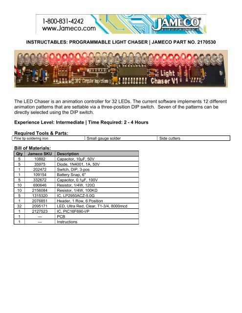
<strong>INSTRUCTABLES</strong>: <strong>PROGRAMMABLE</strong> <strong>LIGHT</strong> <strong>CHASER</strong> | <strong>JAMECO</strong> PART NO. 2170530<br />
The LED Chaser is an animation controller for 32 LEDs. The current software implements 12 different<br />
animation patterns that are settable via a three-position DIP switch. Seven of the patterns can be<br />
directly selected using the DIP switch.<br />
Experience Level: Intermediate | Time Required: 2 - 4 Hours<br />
Required Tools & Parts:<br />
Fine tip soldering iron Small gauge solder Side cutters<br />
Bill of Materials:<br />
Qty Jameco SKU Description<br />
5 10882 Capacitor, 10µF, 50V<br />
5 35975 Diode, 1N4001, 1A, 50V<br />
1 202472 Switch, DIP, 3-pos<br />
1 109154 Battery Snap, 6"<br />
5 332672 Capacitor, 0.1µF, 100V<br />
10 690646 Resistor, 1/4W, 120Ω<br />
10 2156084 Resistor, 1/4W, 100KΩ<br />
5 1315320 IC, LP2950ACZ-5.0G<br />
1 2076851 Header, 1 Row, 6 Position<br />
32 2095171 LED, Ultra Red, Clear, T1-3/4, 8000mcd<br />
1 2127523 IC, PIC16F690-I/P<br />
1 --- PCB<br />
1 --- Instructions
Our Products are Inspired<br />
LED <strong>CHASER</strong><br />
ASSEMBLY INSTRUCTIONS & TECHNICAL MANUAL<br />
Saturday, 6 October 2012<br />
Computer Inspirations • Georgetown ON Canada • www.c-inspirations.com
LED Chaser Assembly Instructions & Technical Manual<br />
Description<br />
The LED Chaser is an animation controller for 32 LEDs. The current software implements 12 different animation<br />
patterns that are settable via a three-position DIP switch. Seven of the patterns can be directly selected according to<br />
the following table:<br />
LED Chaser<br />
DIP SWITCH SETTING ANIMATION PATTERN<br />
Off Off Off Displays all 12 patterns sequentially.<br />
On Off Off Cylon/Knight Rider Scanner<br />
Off On Off Random Computer Lights<br />
On On Off Broadway Marquis<br />
Off Off On Two-eyed Scanner<br />
On Off On Snowfall with Accumulation<br />
Off On On Targeting Scanner<br />
On On On Binary Clock Display<br />
When power is first applied to the LED Chaser, all the LEDs light up sequentially from right to left to help verify that<br />
all the LEDs are working correctly. The rightmost LEDs corresponding to the current software revision light up next:<br />
one LED for version 1, two LEDs for version 2, etc. The pattern associated with the current switch setting is dis-<br />
played next in a continuously repeating cycle. With all switches off, all 13 patterns are displayed sequentially on a<br />
rotating basis with each pattern active for about 10 seconds.<br />
The additional five patterns that are not switch selectable (but are displayed with all switches off) are:<br />
EXTRA PATTERNS ANIMATION PATTERN<br />
0 Runway Lights<br />
8 Double Scan with eyes moving out<br />
9 Animated Sparks<br />
10 Quadruple Scanner with four eyes<br />
11 Fast Binary Counter<br />
12 Double Scan to the Center<br />
It is possible for any of these animation patterns to be assigned to the switches however you like provided you have a<br />
MicroChip IDE, debugger, and compiler. The code for this board was developed using their free MPLAB X IDE V1.30<br />
along with the XC8 C compiler V1.10. The LED Chaser board includes a standard PICKit-compatible programming/<br />
debug connector at reference P2. The source code is available from our web site at www.c-inspirations.com. You can<br />
also develop your own animations by creating a list of LEDs. The default times between animation steps can be set to<br />
Computer Inspirations! Assembly & Technical Manual<br />
1
LED Chaser<br />
anything from 1 mS to about a minute. Any number of LEDs from one to 32 can comprise a scene. However, the<br />
brightness of each LED decreases as the number of LEDs in a scene increases. See below for more details.<br />
Computer Inspirations! Assembly & Technical Manual<br />
2
Assembling the LED Chaser Kit<br />
Please verify that your kit contains the following parts:<br />
1. 1 – 10 "F 50V axial electrolytic capacitor<br />
2. 2 – 0.1 "F 50V ceramic capacitors<br />
3. 4 – 120 # ¼ W resistors<br />
2. 3 – 100K # ¼ W resistors<br />
3. 1 – 10K # ¼ W resistors<br />
4. 1 – Right-angle 0.1” 6-pin header (optional for debug/programming)<br />
5. 1 – 3-position DIP switch<br />
6. 1 – 5V Regulator IC (LP2950CZ5.0)<br />
7. 1 – Preprogrammed microcomputer IC (PIC16F690)<br />
8. 32 – 5mm red LEDs<br />
9. 1 – Rectifier diode (1N4001)<br />
10. 1 – 9V battery clip<br />
11. 1 – LED Chaser PCB<br />
12. 1 – 9V battery (not included in kit)<br />
Note: U2, C4, R5, R7, P3 are reserved for future expansion and are not included in the kit.<br />
Assemble, solder, and clip the leads (where applicable) of these parts in the following order (refer to<br />
PCB outline at the left):<br />
LED Chaser<br />
4 – 120 # resistors located at R1 to R4.<br />
3 – 100K # resistors located at R8 – R10.<br />
1 – 10K # resistor located at R6.<br />
1 – Rectifier diode (1N4001) located at D33 (Important: banded end goes to the top).<br />
1 – 3-position DIP switch located at S1.<br />
2 – 0.1 "F 50V ceramic capacitors located at C2 and C3.<br />
1 – 10 "F 50V ceramic capacitors located at C1.<br />
1 – 9V battery clip at P1 (red wire goes to square pin 1 and black wire to pin 3).<br />
1 – 5V Regulator IC (LP2950CZ5.0) at U1 (Important: flat end as shown).<br />
If you have a volt meter or multimeter, you could now perform a quick test to make sure<br />
the power supply is working correctly. Connect the positive lead of the voltmeter to P2<br />
pin 2 (square pad is pin 1) and the negative lead of the voltmeter to P2 pin 3. Attach the<br />
battery to the battery clip and you should see the voltmeter reading somewhere from<br />
4.95 V to 5.05 V. If not, please double check the soldered connections and make sure all<br />
parts are oriented as shown. Also check for shorts between components pins—especially<br />
the pins of U1 and C1 to C3. If you see the 9V battery voltage at the banded end of D33,<br />
then the problem is likely a bad solder joint or U1 is missing or not working. Disconnect<br />
the battery before continuing.<br />
32 – 5mm red LEDs as marked (Important: notch goes to the top as shown) at D1 to<br />
D32. Install one LED at a time and solder only one pin of the LED to hold it in place.<br />
Then make sure the LED is flush on the PCB board. Reheat the soldered pin to seat the<br />
LED properly—if needed. Solder the remaining lead and clip the excess pins. Repeat<br />
this procedure for the rest of the LEDs.<br />
1 – Right-angle 0.1” 6-pin header (optional) at P2 (if you’re going to develop your own<br />
software or alter the existing software). You will need an extra debug header from Mi-<br />
Computer Inspirations! Assembly & Technical Manual<br />
3
Testing the Assembled Board<br />
crochip if you want to be able to debug the PIC16F690. Note: Use an alternative MPU<br />
such as the PIC16F1829 (pin-compatible) and recompile the code for this target to debug<br />
without requiring the Microchip header.<br />
1 – Preprogrammed microprocessor IC (PIC16F690) at U3 (Important: notch or dot goes<br />
to the bottom as shown).<br />
Once the components have been soldered to the PCB, test the assembly, preferably with a current-limited 9V power<br />
supply or the battery.<br />
1. Connect the +9V power supply lead to the 9V clip leads at P1 (positive to the red wire at pin 1 and negative to the<br />
black wire at pin 3).<br />
2. You should see all the LEDs light up in sequence starting from the top of the board. Then one or more of the top-<br />
most LED(s) should light to indicate the firmware version programmed into the PIC microprocessor. Then, de-<br />
pending on the DIP switch settings, the corresponding animation(s) should start playing.<br />
3. You can change the DIP switch settings at any time. The new setting comes into effect as soon as the active anima-<br />
tion has finished. If all the animations are playing, this mode is aborted whenever the active sequence has com-<br />
pleted.<br />
4. Trouble-shooting if no LEDs light:<br />
a. Go through the power supply trouble-shooting list above.<br />
b. Check all the soldered connections on U3 and resistors R1 to R4.<br />
c. Verify that U3 is programmed by connecting a debugger and verifying the contents of the PIC’s memory are<br />
correct.<br />
5. Trouble-shooting if one or only a few LEDs don’t light:<br />
a. Have all the required resistors R1 to R4 been installed and the solder joints are good?<br />
b. Have all the LEDs been installed with the notch oriented correctly and the solder joints are good?<br />
c. If you suspect one defective LED, apply about 2 V across each LED (notched side is ground) or use a 1K # resis-<br />
tor in series with the 9V power supply.<br />
LED Chaser<br />
Computer Inspirations! Assembly & Technical Manual<br />
4
Technical Description<br />
LED Chaser<br />
The circuit diagram below shows the LED Chaser schematic. Thirty-two LEDs are connected in a “Charlieplexed”<br />
arrangement. A significant advantage of this LED organization is that fewer drive pins are required to handle more<br />
devices than with any other technique. In this case, only eight processor pins are used to drive 32 LEDs. Actually<br />
this circuit uses only a partial Charlieplex arrangement in order to minimize the number of current-limiting resistors.<br />
A full Charlieplex configuration should be able to drive up to 42 LEDs using only seven processor pins. Traditional<br />
multiplexing methods would require at least 12 pins. To protect the LEDs, the maximum current has been limited to<br />
about 20 mA although some LEDs allow higher currents when pulsed. Since this design has a variable number of<br />
LEDs on at a given time, the 20 mA maximum is advisable.<br />
Switch S1 (consisting of three individual switches) selects the animation sequence to be displayed. Pull-up resistors<br />
R8 to R10 provide a default level of logical 1 when a switch is open.<br />
U1 is a linear regulator that provides the 5V supply for the microprocessor, U3. The debug/programming connector<br />
at P2 is provided to allow user-specific changes to the software.<br />
U2 is a 256 Kbit EEPROM that is reserved for future software implementations. It is intended to hold many more<br />
animations than will fit into the PIC’s internal Flash. The expansion connector, P3, is also intended for future soft-<br />
ware additions that will allow multiple LED Chasers to be synchronized together to play a single animation.<br />
LED Chaser Circuit Schematic.<br />
Computer Inspirations! Assembly & Technical Manual<br />
5
LED Chaser Animation<br />
The simplest way to understand the animation process is to study an existing animation sequence. Below is the<br />
“Random Computer Lights” animation sequence:<br />
const uint8_t Random[] = {<br />
4, /* Play with four LEDs */<br />
24, /* 24 * 8 = 192 mS */<br />
4, 1, 9, 15, /* First animation frame */<br />
3, 25, 8, 27, /* Second animation frame */<br />
12, 26, 14, 11,<br />
6, 31, 13, 2,<br />
20, 17, 18, 23,<br />
10, 24, 16, 19,<br />
22, 29, 7, 21,<br />
5, 30, 0, 28,<br />
22, 0, 14, 5,<br />
19, 6, 15, 20,<br />
26, 25, 23, 9,<br />
4, 10, 27, 18,<br />
21, 30, 11, 3,<br />
29, 16, 24, 13,<br />
2, 17, 12, 31,<br />
8, 1, 28, 7 /* Last animation frame */<br />
};<br />
The first byte indicates how many LEDs will be turned on simultaneously (four in this case). The second byte defines<br />
the amount of time that each animation frame (groups of four bytes) is displayed (192 mS for this example). The<br />
software displays each of the four LEDs in each animation for 96 mS and then moves on to display the next frame.<br />
When the last frame is reached, the animation begins at the first frame again.<br />
LEDs are numbered with 0 representing the top-most board LED (D17) and 31 representing the bottom board LED<br />
(D16). Any number greater than 31 (e.g., 32) is not displayable so all the LEDs will be off in that case. This feature is<br />
useful when you have four LEDs in an animation but only want to display one of them (e.g., 0, 32, 32, 32 would light<br />
only the top-most LED). Repeating an animation frame is a simple way of slowing down just a portion of an anima-<br />
tion for a special effect.<br />
If you develop any animations that you would like to share, please email them to sales@c-inspirations.com with a<br />
subject line of “LED Chaser Animation.” The best animations will be featured in future software updates and may<br />
even be given a DIP switch position!<br />
LED Chaser<br />
Note: Using more LEDs in an animation will cause the individual LED brightness to be reduced. This is a limitation<br />
of the Charlieplexing technique used to drive the LEDs. Maximum brightness is achieved using a single LED. Two<br />
LEDs would have ½ the brightness of a single LED. Three LEDs would have about & the brightness, and so on.<br />
Computer Inspirations! Assembly & Technical Manual<br />
6
LED Chaser<br />
Mechanical Dimensions of the LED Chaser PCB<br />
Computer Inspirations! Assembly & Technical Manual<br />
7