Atlas Copco Air Motors
Atlas Copco Air Motors
Atlas Copco Air Motors

Create successful ePaper yourself
Turn your PDF publications into a flip-book with our unique Google optimized e-Paper software.
LZB Vane motors<br />
Introduction<br />
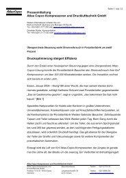
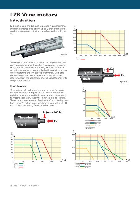
LZB vane motors are designed to provide high performance<br />
and high standards of reliability. Typically, they are characterized<br />
by a high power output and small physical size, Figure<br />
14.<br />
The design of the motor is chosen to be long and slim. This<br />
gives a number of advantages like a high power to volume<br />
ratio, a low air consumption and long vane life. All motors<br />
utilise five vanes, which are supplied with vane air, to ensure<br />
excellent starting and low speed performance. Multi-step<br />
planetary gears are used to meet the torque and speed<br />
requirements of the application, offering high efficiency with<br />
compact dimensions.<br />
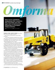
Shaft loading<br />
Figure 14<br />
The maximum allowable loads on a given motor´s output<br />
shaft are illustrated in Figure 15. The relevant load curve<br />
code for a motor is stated in the data tables for each specific<br />
motor designation, under the ”Shaft load code” column.<br />
These values have been calculated for shaft and bearing working<br />
lives of 10 million turns. To achieve a working life of 100<br />
million turns, the loading factor must be halved.<br />
Fr (max 400 N)<br />
Threaded<br />
Fa Fa<br />
shaft<br />
Fr<br />
(N)<br />
450<br />
400<br />
350<br />
300<br />
250<br />
200<br />
150<br />
100<br />
50<br />
0<br />
Curve a<br />
Curve b<br />
Curve c<br />
500 1000<br />
1500 2000<br />
2500<br />
1 2 AT L A S C O P C O A I R M O T O R S<br />
Fa<br />
(N)<br />
Fr<br />
(N)<br />
3500<br />
3000<br />
2500<br />
2000<br />
1500<br />
1000<br />
Fr<br />
(N)<br />
4000<br />
3000<br />
2000<br />
1000<br />
500<br />
500<br />
Curve e<br />
Curve g<br />
1000 1500 2000 2500 3000 3500 4000 4500<br />
Curve h<br />
Curve g<br />
Curve f<br />
Curve e<br />
Cylindric<br />
shaft<br />
Fr<br />
(N)<br />
2000<br />
1500<br />
1000<br />
500<br />
Curve d<br />
Curve c<br />
Curve b<br />
Curve a<br />
1000 2000<br />
A = 20 mm<br />
A = 15 mm<br />
A = 20 mm<br />
A = 15 mm<br />
500<br />
Coversion factor<br />
1N = 0.225 lbf<br />
1000<br />
A = 20 mm<br />
A = 15 mm<br />
A = 9 mm<br />
A = 8 mm<br />
3000<br />
Fr<br />
1500<br />
4000<br />
A<br />
2000<br />
5000<br />
Fa<br />
(N)<br />
6000<br />
Fa<br />
5000<br />
Fa<br />
(N)<br />
Figure 15<br />
7000<br />
Fa<br />
(N)<br />
Threa<br />
shaft