Atlas Copco Air Motors
Atlas Copco Air Motors
Atlas Copco Air Motors

Create successful ePaper yourself
Turn your PDF publications into a flip-book with our unique Google optimized e-Paper software.
LZL Vane motor/gear unit<br />
combinations<br />
Combined with helical or worm gear units,<br />
type LZL vane air motors can be used over a<br />
very wide torque and speed range. Models are<br />
nominally available with gear ratios that range<br />
from 8:1 to 240:1, corresponding to a speed<br />
range of 460 to 10 r/min and an output torque<br />
of up to 5000 Nm.<br />
Helical gear units type HG.<br />
Helical gear units are available in 2-stage and 3-stage configurations.<br />
They deliver high efficiency levels and are available in<br />
wide choice of ratios, Figure 22.<br />
Worm gear units type BS<br />
Figure 22<br />
Worm gear units are smaller and lighter in operation than<br />
helical gear units. However, they offer lower levels of efficiency.<br />
Where the highest gear ratios are required, it should<br />
be noted that starting efficiency can be as low as 30% ,<br />
Figure 23.<br />
A hollow shaft can be obtained by taking out the cylindrical<br />
output shaft for BS 50, BS 63 and BS 71.<br />
Figure 23<br />
Note. Gear units with different reduction ratios can be supplied to special<br />
order. For comprehensive information on these versions, please contact<br />
your local <strong>Atlas</strong> <strong>Copco</strong> representative.<br />
5 4 AT L A S C O P C O A I R M O T O R S<br />
Shaft loading<br />
<strong>Motors</strong> with helical gear units<br />
The maximum allowable radial load on the output shaft of<br />
each gear unit, at the half way point on the shaft can be<br />
obtained from the data tables for each model.<br />
The maximum permitted axial load is 50% of the radial load.<br />
All units will accept 100% momentary overloads on above<br />
stated capacities<br />
<strong>Motors</strong> with worm gear units<br />
Worm gear units have individual output shafts and the allowable<br />
radial load is therefore different for each version. The<br />
maximum allowable radial load, at the half way point on the<br />
shaft, is stated in the worm gear data tables on page 62, 64<br />
and 66.<br />
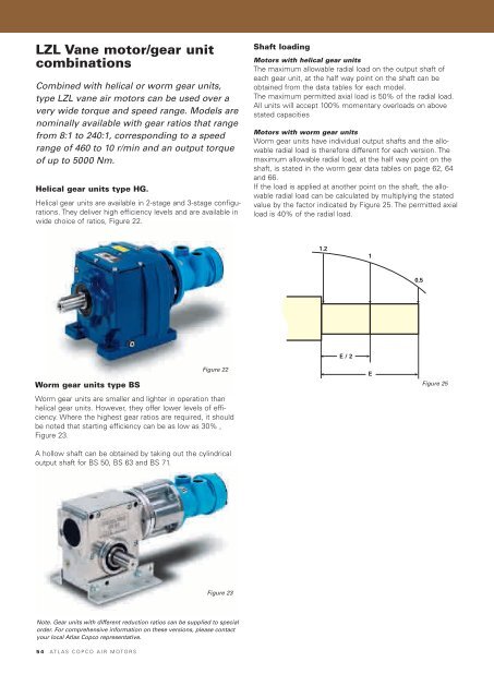
If the load is applied at another point on the shaft, the allowable<br />
radial load can be calculated by multiplying the stated<br />
value by the factor indicated by Figure 25. The permitted axial<br />
load is 40% of the radial load.<br />
1.2<br />
E / 2<br />
1<br />
E<br />
0,5<br />
Figure 25