


Create successful ePaper yourself
Turn your PDF publications into a flip-book with our unique Google optimized e-Paper software.
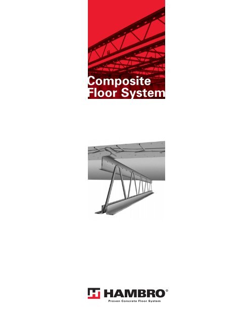
Composite<br />
Floor System
INTRODUCTION<br />
This manual has been developed<br />
in order to assist you<br />
in understanding the <strong>Hambro</strong> ®<br />
Composite Floor System,<br />
and for you to have at your fingertips<br />
the information necessary<br />
for a simple and economical<br />
use of our <strong>Hambro</strong> Products.<br />
Suggested detailing and<br />
design information throughout<br />
this manual illustrates methods of use.<br />
To achieve maximum economy and<br />
to save valuable time, we suggest that you<br />
contact your local <strong>Hambro</strong> representative,<br />
who is qualified and prepared<br />
to assist in the selection of a <strong>Hambro</strong><br />
system that is best suited<br />
for your project’s requirements.<br />
U.S.PATENT Nos:<br />
3818083 3819143<br />
3841597 3845594<br />
3913296 3945168<br />
3979868 4015396<br />
4584815 4729201<br />
CANADA PATENT N o :<br />
874180<br />
OTHER U.S. & FOREIGN PATENTS PENDING<br />
www.hambro.ws<br />
Underwriters<br />
Laboratories Inc.®<br />
1
GENERAL INFORMATION<br />
DESCRIPTION<br />
The <strong>Hambro</strong> Composite Floor System has been used with<br />
different types of construction i.e. masonry, steel frame<br />
buildings, poured in place or precast concrete as well as wood<br />
construction, from the single family detached house to<br />
multistory residential and office complexes.<br />
The unique top chord section has three basic functions:<br />
1. It is a compression member component of the <strong>Hambro</strong><br />
non-composite joist during the concreting stage.<br />
Remember that the system is not shored.<br />
2. It is a “high chair” for the welded wire mesh, developing<br />
negative moment capacity in the concrete slab<br />
where it is required - over the joist top chord.<br />
3. It locks with and supports the slab forming system<br />
(rollbars and forms).<br />
4. It automatically becomes a continuous shear connector<br />
for the composite stage.<br />
The <strong>Hambro</strong> Composite Floor System essentially consists of<br />
a hybrid concrete/steel tee-beam in one direction and an<br />
integrated continuous one-way slab in the other direction, and<br />
is illustrated in figures 1 and 2.<br />
Depending on the span, the loads and the type of form to<br />
support concrete poured in place, the <strong>Hambro</strong> steel joist may<br />
have a different configuration at top chord.<br />
The bottom chord acts as a tension member during both the<br />
concreting stage and the service life.<br />
The web system, consisting of bent rods, ties the top and<br />
bottom chords together and resists the vertical shear in the<br />
conventional truss manner.<br />
The concrete slab is reinforced with welded wire mesh at the<br />
required locations and behaves structurally as a continuous<br />
one-way reinforced concrete slab.<br />
1
GENERAL INFORMATION<br />
* Normally 4’-1 1/4” to accommodate standard 4’-0” wide<br />
plywood forms, but can be altered to suit job conditions.<br />
The rigid plywood sheets and rollbars, when locked into the<br />
section, not only act as simple forms for placing concrete,<br />
but provide the essential lateral and torsional stability to the<br />
entire <strong>Hambro</strong> floor system during the concreting stage.<br />
The interaction between the concrete slab and <strong>Hambro</strong> joist<br />
begins to occur once the wet concrete begins to set. The<br />
necessary composite interaction for construction loads is<br />
achieved once the concrete strength, f’ c, reaches 1,000 psi.<br />
This will usually occur within 24 hours. Even in the coldest of<br />
winter concrete pouring conditions, construction heating will<br />
maintain the concrete at temperatures necessary for this<br />
strength gain. When in doubt, concrete test cylinders can be<br />
used to verify strength.<br />
The result is a composite floor system having a sound<br />
transmission class (STC) of 57 with the addition of a gypsum<br />
board ceiling.<br />
Fire resistance ratings of up to 3 hours are easily achieved with<br />
the <strong>Hambro</strong> Composite Floor System by the installation of a<br />
gypsum board ceiling directly under the joists. Other types of<br />
fire protection could be used. Refer to U.L.I. publications for<br />
their use.<br />
The <strong>Hambro</strong> Composite Floor System has been subjected<br />
to many tests both in laboratories and in the field.<br />
2<br />
2 1/2” concrete<br />
slab (min.)<br />
Web<br />
Bottom<br />
chord<br />
Shear connector<br />
embedded 1 1/2î<br />
into slab<br />
4’-0” plywood sheet<br />
Draped<br />
mesh<br />
Rollbar locked<br />
into section<br />
<strong>Hambro</strong> joist spacing*<br />
Fig. 2<br />
ADVANTAGES<br />
• The <strong>Hambro</strong> joists are custom manufactured to suit particular<br />
job conditions and are easily installed. <strong>Hambro</strong> joist modular<br />
spacing can be adjusted to suit varying conditions.<br />
• The <strong>Hambro</strong> forming system provides a rigid working<br />
platform. Masonry walls or tie beams may be filled, when<br />
required, using the <strong>Hambro</strong> floor as a working deck.<br />
• Shallower floor depths can be used because of the increased<br />
rigidity of the system resulting from the composite action.<br />
• The wide <strong>Hambro</strong> joist spacing allows greater flexibility for<br />
mechanical engineers and contractors. Standard pipe lengths<br />
can be threaded through the <strong>Hambro</strong> web system - this<br />
means fewer mechanical joints.<br />
• The ceiling plenum can accommodate all electrical and<br />
mechanical ducting, eliminating the need for bulkheading<br />
and dropped ceilings.<br />
• The interlocking of concrete with steel provides excellent<br />
lateral diaphragm action with the composite joists acting as<br />
stiffeners for the entire system.<br />
• Other subtrades can closely follow <strong>Hambro</strong>, shortening your<br />
project’s completion time.<br />
• The rollbars and plywood sheets are reusable.
SPECIFICATIONS<br />
PART 1-GENERAL<br />
1.1 INCLUDES<br />
A. Composite floor joist system of steel joists with cast-inplace<br />
concrete slab.<br />
1.2 RELATED SECTIONS<br />
A. Section 03300 Cast-In-Place Concrete.<br />
1.3 REFERENCES<br />
A. ACI 301 - Specifications for Structural Concrete<br />
B. ACI 318 - Building Code Requirements for Structural<br />
Concrete<br />
C. AISC Specification for the Design of Cold-Formed Steel<br />
Structural Members<br />
D. ASTM A 1008 Standard Specification for Steel, Sheet,<br />
Cold-Rolled, Carbon, Structural, High-Strength Low-Alloy<br />
and High Strength Low-Alloy with Improved Formability.<br />
E. ASTM C 39 - Standard Test Method for Compressive<br />
Strength of Cylinders Concrete Specimens.<br />
F. AWS D1.1 Structural Welding Code Steel.<br />
G. Steel Joist Institute (SJI)<br />
1.4 DESIGN REQUIREMENTS<br />
A. Design of Composite Floor Joist System:<br />
1. Flexural Design: Ultimate Strength Method and as<br />
described by manufacturer.<br />
2. Joist Top Chord Member: AISC Specification for<br />
the Design of Cold-Formed Steel Structural<br />
Members.<br />
3. Joist Web & Bottom Chord members: (SJI)<br />
4. Concrete Slab: ACI 318<br />
B. Design Joists to Resist Combined Weight of:<br />
1. Wet concrete (specified slab thickness)<br />
2. Welded wire fabric reinforcement<br />
3. Formwork<br />
4. Rollbar<br />
5. Construction Load: 20 psf maximum<br />
1.5 SUBMITTALS<br />
A. Comply with Section 01330 Submittal Procedures.<br />
B. Product Data: Submit manufacturer’s product data for<br />
composite floor joist system.<br />
C. Shop Drawings: Submit manufacturer’s shop drawings<br />
indicating material lists; mark numbers; types, locations<br />
and spacing of joists and accessories; and special conditions<br />
requiring top or bottom bracing.<br />
1. Calculated dimensions on shop drawings shall be<br />
used.<br />
2. Scaling of drawings shall not be permitted.<br />
D. Product Certificates: Submit manufacturer’s product<br />
certificates signed by manufacturer, certifying materials<br />
comply with specified requirements.<br />
E. Welder’s Certifications: Submit welders’ certifications<br />
signed by Contractor certifying welders comply with<br />
quality assurance requirements.<br />
1.6 QUALITY ASSURANCE<br />
A. Welding Materials and Methods of Fabrication:<br />
Manufacturer’s standard shop practice.<br />
B. Welder’s Qualifications: Certify that each welder is AWS<br />
certified in accordance with AWS D1.1<br />
1. Joist Repairs and Modifications in Field:<br />
Performed by AWS certified welders in accordance<br />
with AWS D1.1.<br />
1.7 DELIVERY, STORAGE AND <strong>HA</strong>NDLING<br />
A. Delivery:<br />
B. Storage:<br />
C. Handling:<br />
1. Deliver joists to site banded in nested bundles and<br />
tagged with Identification Plate attached at one<br />
end, at joist shoe.<br />
2. Indicate on Joist Identification Plates:<br />
a. Manufacturer<br />
b. Country (Plant)<br />
c. Project number<br />
d. Joist mark<br />
1. Store materials in accordance with manufacturer’s<br />
instructions.<br />
2. Protect materials from corrosion, deformation, and<br />
other damage.<br />
3. Store joists upright on level surface, off ground.<br />
4. Do not stack joists.<br />
1. Protect joists from damage during unloading,<br />
storage, handling, and installation.<br />
2. Hoist joists by crane in accordance with manufacturer’s<br />
instructions.<br />
1
SPECIFICATIONS<br />
PART 2-PRODUCTS<br />
2.1 MANUFACTURER<br />
A. <strong>Hambro</strong><br />
450 E. Hillsboro Blvd<br />
Deerfield Beach, Florida 33441<br />
Phone: 1-800-546-9008 / (954) 571-3030<br />
Fax: 1-800-592-4943 / (954) 571-3031<br />
Website: www.hambro.ws<br />
2.2 COMPOSITE FLOOR JOIST SYSTEM<br />
A. Designation: <strong>Hambro</strong> Composte Floor Joist System<br />
B. Joists, Rollbar, and Standard Bearing Shoes: Furnished<br />
by Manufacturer<br />
C. Joists:<br />
D. Rollbar<br />
2<br />
1. Joist Depth: as indicated on the drawings.<br />
2. Top chord member:<br />
a. Act as a continuous shear connector<br />
b. ASTM A 1008, Grade 50, cold rolled steel,<br />
13 gauge minimum<br />
c. Fy : 50,000 psi minimum<br />
3. Bottom Chord Member:<br />
a. Hot-rolled or cold-rolled steel angles<br />
b. Fy : 50,000 psi minimum<br />
4. Web Members:<br />
a. Hot-rolled steel bars, 7/16 inch diameter<br />
minimum, some continuous<br />
b. Bent at top chord joist locations<br />
c. Fy : 44,000 psi minimum<br />
5. Shop painting: Rust-inhibitive primer<br />
1. Steel<br />
2. Removable<br />
3. Design to support the following, until formwork is<br />
removed after concrete has reached a minimum<br />
compressive strength of 500 psi, determined by<br />
testing concrete cylinders in accordance with<br />
ASTM C 39.<br />
a. Plywood forms<br />
b. Slab dead weight<br />
c. Welded wire fabric weight<br />
d. Construction Load 40 psf<br />
4. Act as temporary bridging and spacers for joists.<br />
E. Standard Bearing Shoes<br />
1. Angle Shape: Steel, 4 inches by 1 3/4 inches<br />
by 1/4 inch, 4 3/4 inches wide, unless otherwise<br />
indicated on the drawings<br />
2. Shop Painting: Rust-inhibitive primer<br />
F. Forms: Plywood<br />
G. Concrete:<br />
1. Sheets: 4 feet by 8 feet typical<br />
2. Thickness: 3/8 inch, 1/2 inch, 5/8 inch or 3/4 inch<br />
1. Minimum Ultimate Compressive Strength,<br />
f’ c : 3,000 psi @ 28 days<br />
2. Standard Weight: 145 pcf<br />
3. Maximum Aggregate Size: 3/4 inch<br />
4. As specified in Section 03300, unless specified<br />
otherwise in this section.<br />
H. Concrete Reinforcement: welded wire fabric.<br />
1. Size: As indicated on the drawings.<br />
2. Fy : 60,000 psi minimum<br />
3. Flat Sheets. Do not use rolls.<br />
4. As specified in Section 03300 unless specified<br />
otherwise in this section.<br />
2.3 FABRICATION<br />
A. Fabrication: Manufacturer’s standard shop practice.<br />
B. Joist Top Chord: Fabricate joist top chord to allow for<br />
1-1/2 inches embedment into concrete slab.<br />
C. Joist Cambers: Camber is optional, but when provided,<br />
approximate camber will be as follows:<br />
Joist Span (Range): Prefabricated Camber<br />
15 ft. to 20 ft. 1/2 in. to 3/4 in.<br />
20 ft. to 25 ft. 3/4 in. to 7/8 in.<br />
25 ft. to 30 ft. 7/8 in. to 1 1/16 in.<br />
30 ft. to 40 ft. 1 1/16 in. to 1 1/2 in.<br />
2.4 SOURCE QUALITY CONTROL<br />
A. Joists:<br />
1. Manufacturer’s facility having continuous quality<br />
control program and subjected to plant inspections<br />
by approved independent agency.<br />
2. Inspection shall include checking:<br />
a. Size<br />
b. Span<br />
c. Assembly<br />
d. Welds
SPECIFICATIONS<br />
PART 3-EXECUTION<br />
3.1 EXAMINATION<br />
A. Examine areas to receive composite floor joist system.<br />
B. Notify Engineer of conditions that would adversely<br />
affect installation.<br />
C. Do not start installation until unsatisfactory conditions<br />
are corrected.<br />
3.2 INSTALLATION<br />
A. Install composite floor joist system in accordance with<br />
the following:<br />
1. Manufacturer’s installation manual<br />
2. Approved erection drawings<br />
3. Amendments issued by manufacturer<br />
B. Construction Loads<br />
1. Do not exceed load-carrying capacity of composite<br />
floor joist system with construction loads.<br />
2. Concentrated construction loads: Do not place<br />
loads (i.e. bundles of plywood, sheetrock or<br />
rollbar), exceeding the design load of the slab, on<br />
joist system, but rather on supporting walls or beam.<br />
3. Concentrated Construction Loads Exceeding<br />
Design Load Capacity: Construction Loads exceeding<br />
the design load capacity of the floor system must<br />
be fully supported, and shored to grade.<br />
C. Erect joists level, plumb and to proper locations and elevations.<br />
D. Perform shimming as required with metal shim material,<br />
ensuring total shoe contact.<br />
E. Special Conditions requiring top and/or bottom bracing<br />
shall be indicated on the erection drawings, prepared by<br />
the manufacturer.<br />
F. End Anchorage: Anchor or embed joist shoes as indicated<br />
on the drawings.<br />
G. Joist Sweep: After installation, allowable joist sweep shall<br />
be 1 inch in 20 feet.<br />
H. Construction Loads: Do not exceed load carrying capacity<br />
of composite floor joist system with construction loads.<br />
I. Minimum Joist Bearing:<br />
1. Steel Supports: 2 1/2 inches<br />
2. Masonry and Concrete Supports: 3 1/2 inches<br />
3. Bearing Capacity of Supporting Units: Comply with<br />
applied shoe end reaction, based on minimum<br />
supplied bearing areas as follows:<br />
a. Bearing on structural steel: 11.8 square inches<br />
b. Other Bearing Conditions: 16.6 square inches<br />
J. Damaged Joists:<br />
1. Do not install damaged joists.<br />
2. Repair or replace damaged joists before installation.<br />
3. Do not make field repairs to damaged joists<br />
without written approval from the manufacturer<br />
and Engineer.<br />
4. Make repairs to damaged joists in accordance with<br />
repair details from the manufacturer.<br />
5. Receive written approval from Engineer of joist<br />
repair before installation.<br />
3.3 CONCRETE PLACEMENT<br />
A . Concrete:<br />
1. In accordance with ACI 301<br />
2. As specified in Section 03300, unless specified<br />
otherwise in this Section.<br />
B. Welded Wire Fabric:<br />
1. Laps: In accordance with ACI 318<br />
2. As specified in Section 03300, unless specified<br />
otherwise in this section.<br />
C. Place concrete to slab thickness as indicated on the<br />
drawings. Do not pour concrete in excess of the thickness<br />
indicated on the drawings.<br />
D. Maintain minimum depth of concrete cover above joist top<br />
chord in accordance with manufacturer’s instructions.<br />
E. Construction Loads: Do not drop bucket loads of concrete<br />
in concentrated area over joists.<br />
F. Vibrate concrete lightly but thoroughly. Ensure full encasement<br />
of the joist top chord in concrete.<br />
G. Construction Joints:<br />
i. Parallel to Joists:<br />
1. Locate construction joints midway between joists.<br />
2. Do not locate construction joints closer than<br />
6 inches from top chord.<br />
ii. Perpendicular to joists:<br />
1. Locate construction joints over supporting wall<br />
or beam.<br />
H. Formwork Removal: Remove formwork after concrete has<br />
reached a minimum compressive strength of 500 psi, as<br />
determined by testing concrete cylinders in accordance<br />
with ASTM C 39.<br />
3.4 PROTECTION<br />
A. Protect concrete from foot traffic until concrete has<br />
reached a minimum compressive strength of 1,000 psi, as<br />
determined by testing concrete cylinders in accordance<br />
with ASTM C 39.<br />
3
FIRE RATINGS<br />
Fire Protection floor/ceiling assemblies using <strong>Hambro</strong> ® have<br />
been tested by independent laboratories. Fire resistance<br />
ratings have been issued by Underwriters Laboratories Inc.<br />
which cover gypsum board, accoustical tile and spray on<br />
protection systems. Reference to these published listings<br />
should be made in detailing ceiling construction. Check your<br />
UL directory for the latest updating of these listings, or see<br />
the UL website at http://www.ul.com/database<br />
UL/ULC/cUL RATING SLAB THICKNESS CEILING BEAM RATING<br />
DESIGN # (hr.) (in.) (hr.)<br />
I506<br />
I518<br />
* Normal and lightweight concrete.<br />
2 2 1/2 Gypboard 1/2” -<br />
2 3 1/2 Gypboard 1/2” -<br />
1 1/2 2 1/2 Gypboard 1/2” 2<br />
2 2 1/4 - 3 Gypboard 1/2” 2<br />
I800 1 - 1 1/2 - 2 2 1/2 - 2 3/4 Spray on 1<br />
G003 2 2 1/2 Suspended or panel -<br />
G213<br />
2 3 Suspended or panel 2<br />
3 4 Suspended or panel 3<br />
G227 2 2 1/2 Suspended or panel 3<br />
G228 2 3 1/4 Suspended or panel 2<br />
G229<br />
2 3 Suspended or panel 2<br />
3 4 Suspended or panel 3<br />
G401 4 2 1/2 Plaster -<br />
G524<br />
1 - 2 2 1/2* Gypboard 1/2” 2<br />
3 3 1/2* Gypboard 1/2” 3<br />
G525 3 3 1/4 Gypboard 5/8” 3<br />
G702 1 - 2 - 3 Varies* Spray on -<br />
G802 1 - 2 - 3 Varies* Spray on -<br />
1
ACOUSTICAL PROPERTIES<br />
SOUND TRANSMISSION<br />
Because sound transmission depends upon a number of variables<br />
relating to the installation and materials used, <strong>Hambro</strong> makes no<br />
representations about the sound transmission performance of its<br />
products as installed. You should consult with a qualified acoustical<br />
consultant if you would like information about sound performance.<br />
ACOUSTICAL CONSULTANTS<br />
The following is a list of readily accessible acoustical<br />
consultants found on the World Wide Web, and is not a<br />
recommended list. <strong>Hambro</strong> has not researched their<br />
qualifications and cannot make any representation about<br />
their abilities.<br />
Archicoistics/Acoustinet<br />
Claude Venet<br />
7725 NW 25th St., #300<br />
Miami FL 33122<br />
305-981-2500<br />
Bertram Y. Knizey Jr.<br />
212 SW 42nd Street<br />
Gainesville, FL. 32607<br />
352-378-1878<br />
Dunn & Associates<br />
P.O. Box 121308<br />
Clermont, FL 34711<br />
352-394-0621<br />
Fagen Acoustical<br />
Consultants<br />
P.O. Box 1975<br />
St. Petersburg, FL 33701<br />
727-823-3564<br />
Siebein Associates and Octave Acoustique have worked<br />
directly for <strong>Hambro</strong> and some of our customers.<br />
<strong>HA</strong>MBRO SOUND INFORMATION<br />
Octave Acoustique, Inc.<br />
Christian Martel, M.Sc. Arch<br />
963, chemin Royal<br />
Saint-Laurent-del’Ile-d’Orleans<br />
(Québec) Canada G0A 4N0<br />
418-844-3338<br />
Pelton Marsh Kinsella<br />
4045 Sheridan Ave.,<br />
Suite 420<br />
Miami Beach, FL 33140<br />
305-381-6970<br />
Siebein Associates, Inc.<br />
625 NW 60th Street<br />
Suite C<br />
Gainesville, FL 32607<br />
352-331-5111<br />
<strong>Hambro</strong> Assemblies STC IIC<br />
2 1/2” slab, 1 layer 1/2” drywall 52 26<br />
3” slab, 1 layer 1/2” drywall 57 30<br />
4” slab, 1 layer 1/2” drywall 58 32<br />
4” slab, 2 layer 1/2” drywall 60 36<br />
Completed <strong>Hambro</strong> floor/ceiling assemblies are available<br />
for additional floor finishes testing at NGC. Contact NGC<br />
directly or Jerry Rhodes, <strong>Hambro</strong>, at<br />
jerry.rhodes@hambro.ws.<br />
IMPACT OF FLOOR FINISHES &<br />
<strong>HA</strong>MBRO FLOOR SYSTEM<br />
Floor Finishes IIC Ratings<br />
Carpet and Pad 50<br />
Homasote 1/2” comfort base 44<br />
under wood laminate<br />
www.homasote.com<br />
6 mm cork under engineered hardwood 47<br />
Dodge Regupol 4010 46<br />
10 mm underlayment under ceramic tile<br />
www.regupol.com<br />
Quiet Walk underlayment 45<br />
under laminate flooring<br />
www.mpglobalproducts.com<br />
Insulayment under engineered wood 46<br />
www.mpglobalproducts.com<br />
1 1/2” Maxxon gypsum 54<br />
underlayment over Enkasonic<br />
sound control mat with quarry<br />
tile over Noble Seal SIS<br />
www.maxxon.com<br />
1 1/2” Maxxon gypsum 55<br />
underlayment over Enkasonic<br />
sound control mat with wood<br />
laminate floor over silent step<br />
www.maxxon.com<br />
1 1/2” Maxxon gypsum 53<br />
underlayment over Enkasonic<br />
sound control mat w/Armstong<br />
Commissions Plus Sheet Vinyl<br />
www.maxxon.com<br />
* All products tested were on a 2 1/2” <strong>Hambro</strong> slab with a<br />
one layer 1/2” drywall ceiling. This chart is provided as a<br />
reference. The calculations of sound rating and design<br />
of floor/ceiling assemblies with regard to acoustical<br />
properties is a building designer/specialty engineering<br />
responsibility. Actual field results may vary depending on<br />
installation and materials. All product tests were<br />
performed at NGC Testing Services, Buffalo NY,<br />
www.ngctestingservices.com<br />
STC RATINGS: W<strong>HA</strong>T THEY MEAN<br />
STC Rating Practical Guidelines<br />
25 Normal speech easily understood<br />
30 Normal speech audible, but not intelligible<br />
35 Loud speech audible,<br />
fairly understandable<br />
40 Loud speech audible,<br />
but not intelligible<br />
45 Loud speech barely audible<br />
50 Shouting barely audible<br />
55 Shouting inaudible<br />
1
ACOUSTICAL PROPERTIES<br />
2
ACOUSTICAL PROPERTIES<br />
3
DESIGN PRINCIPLES AND CALCULATIONS - SLAB DESIGN<br />
THE <strong>HA</strong>MBRO SLAB<br />
The slab component of the <strong>Hambro</strong> D500 Composite Floor<br />
System behaves as a continuous one-way slab carrying loads<br />
transversely to the joists, and often is required to also act as a<br />
diaphragm carrying lateral loads to shear walls or other lateral<br />
load resisting elements.<br />
At the present time, the <strong>Hambro</strong> slab has been designed by<br />
conventional ultimate strength design procedures of ACI 318<br />
and section capacities are based on ultimate strength<br />
principles while the moments are still determined by using<br />
the elastic moment coefficients for continuous spans. This<br />
procedure is present in most other building codes.<br />
In accordance with most building code requirements, the<br />
<strong>Hambro</strong> slab capacity is determined for two basic loading<br />
arrangements: a) uniform dead and live load extending in all<br />
directions, and b) a “standard” concentrated live load, applied<br />
anywhere, together with the slab dead loads. It is important to<br />
remember that the live load arrangements of a) and b) do not<br />
occur simultaneously. These loading arrangements will be discussed<br />
in detail.<br />
MOMENT:<br />
The basic ultimate strength moment expressions from ACI are<br />
shown below:<br />
Where<br />
M u = A s a u d .......................................... (1)<br />
Mu = ultimate moment capacity of slab<br />
(ft.-kips/ft. width)<br />
As = area of reinforcing mesh in the direction of<br />
the slab span (in. 2 /ft. width)<br />
au = øfy (1 - .59 w) /12000<br />
ø = flexure factor = 0.9<br />
fy = yield strength of reinforcing mesh = 60,000 psi<br />
(or as calculated by the ACI offset provision)<br />
w = p<br />
p = tension steel ratio = As /bd<br />
f’ c<br />
= compressive strength of concrete<br />
= 3,000 psi<br />
b = unit slab width = 12”<br />
d = distance from extreme compression fibre to<br />
centroid of reinforcing mesh (in.)<br />
= 1.6” for 2 1/2” slab<br />
fy f’ c<br />
It is a simple matter, then, to determine M u for any combination<br />
of A s and d. Taking into account 3/4” concrete cover, “d” is<br />
taken to be 1.6” for the 2 1/2” slab thickness. The ACI Ultimate<br />
Strength Design Handbook Vol. 1, Publication SP17, contains<br />
tabulated values for “a u ” (note that a u increases as the<br />
tension steel ratio “p” decreases).<br />
CRACK CONTROL PROVISIONS:<br />
When design yield strength f y for tension reinforcement<br />
exceeds 40,000 psi, cross sections of maximum positive and<br />
negative moment shall be so proportioned that the quantity z<br />
given by:<br />
z = f s 3 dc A .................... (2) [ACI 10.6.3.4]<br />
does not exceed 175 kips per in. for interior exposure and<br />
145 kips per in. for exterior exposure. Calculated stress in<br />
reinforcement at service load f s (kips per sq. in.) shall be<br />
computed as the moment divided by the product of steel area<br />
and internal moment arm. In lieu of such computations, f s may<br />
be taken as 60 percent of specified yield strength f y .<br />
t<br />
√<br />
Considering the negative moment region where the mesh rests<br />
directly on the embedded top chord connector, the centroid of<br />
the mesh is 1.6” above the extreme concrete compression<br />
fibre. With 6” wire spacing and t = 2 1/2”, d c = 0.9”;<br />
A (hatched area) = 1.8 x 6 = 10.8 in. 2 ;<br />
Using fs = 60% of 60 ksi = 36 ksi;<br />
“z” in formula 2 becomes 77 kips per inch.<br />
Even for a 3” slab with the lever arm still at 1.6” and d = 1.4”,<br />
“z” = 103 kips per inch, well under the allowable.<br />
SHEAR STRESS<br />
Width<br />
Fig. 1<br />
The ultimate shear capacity, v cu , which is a measure of<br />
diagonal tension, is unaffected by the embedment of the top<br />
chord section as this principal tensile crack would be inclined<br />
and radiate away from the z section. Furthermore, there is no<br />
vertical weak plane through which a premature “punching<br />
shear” type of failure could occur.<br />
d c<br />
d c<br />
1
DESIGN PRINCIPLES AND CALCULATIONS - SLAB DESIGN<br />
A check of the vcu capacity for d = 1.6” (2 1/2” slab) and<br />
f’ c = 3,000 psi is shown:<br />
vcu = ............................................. (3)<br />
Vu øbd<br />
2<br />
V ............................................. (4)<br />
u = øvcubd Substituting the following values in (4): vcu = 2 f’ c = 100 psi,<br />
b = 12”, d = 1.6”, ø = .85, results in:<br />
V u = 1,785 lbs.<br />
With a Load Factor of 1.7, the 2 1/2” slab spanning 4-1 1/4”<br />
c/c has a safe shear capacity of 525 psf.<br />
DEFLECTION:<br />
The span / thickness ratio 49.5 / 2.5 = 20 is less than the maximum<br />
allowable 24 for the one end continuous condition. Slab<br />
deflection, Δ, due to a uniformly distributed load, can be writ-<br />
ten as:<br />
........................................ (5)<br />
Δ<br />
= ........................................ (6)<br />
K1wL3 L EcIc For the same w, E c and slab end conditions, (6) can be rewritten:<br />
Hence, the Δ / L ratios of different floors can be used to<br />
assess relative deflection.<br />
Example:<br />
Δ =<br />
Δ<br />
= K2<br />
L<br />
K1wL 4<br />
E c I c<br />
L 3<br />
I c<br />
<strong>HA</strong>MBRO 2 1/2” SLAB / 4’ - 1 1/4” SPAN<br />
I c = 12 (2.5) 3 /12 = 15.6 in. 4<br />
Δ / L = L 3 / I c = (4.1) 3 / 15.6 = 4.4<br />
7 1/2” SLAB / 20’ SPAN<br />
I c = 12 (7.5) 3 /12 = 422 in. 4<br />
Δ / L = L 3 / l c = (20) 3 / 422 = 19<br />
Clearly, then, the <strong>Hambro</strong> slab deflections expressed in<br />
terms of Δ / L are less with <strong>Hambro</strong> than with a 7 1/2” slab<br />
spanning 20’.<br />
√<br />
UNIFORM LIVE LOAD ARRANGEMENT:<br />
Generally, the slab capacity is checked against the condition<br />
where the dead and live loads are uniformly distributed.<br />
A load factor of 1.7 is used for both dead and live load capacities.<br />
For a more exact analysis, factored loads of 1.4D and<br />
1.7L should be considered.<br />
Refer to Fig. 2 for location of the design moments below.<br />
Ultimate positive moment, M u :<br />
exterior span 1.7 w s L 1 2 /11 ................... location 1<br />
interior span 1.7 w s L 2 2 /16 .................... location 3<br />
Ultimate negative moment, M u :<br />
Where<br />
exterior span 1.7 w s L 2 /10 ..................... location 2<br />
interior span 1.7 w s L 2 2 /11 .................... location 4<br />
L 1 ,L 2 = clear span (ft.) is less than 1 3/4” less<br />
than joist spacing.<br />
L = average of L 1 and L 2 (ft.)<br />
ws = total design load (dead + live) in psf<br />
Note that a conservative load factor of 1.7 has been used for<br />
dead and live load.<br />
When L 1 = L 2 , maximum mesh stress occurs at location 2.<br />
When L 1 ≤ 0.9 L 2 , maximum mesh stress occurs at location 4.<br />
The slab load tables are reproduced in Table 1.
DESIGN PRINCIPLES AND CALCULATIONS - SLAB DESIGN<br />
Table 1 - Slab Capacity Chart (Total Load in psf)<br />
SLAB d MESH SIZE 4’-1 1/4” JOIST SPACING<br />
THICKNESS (t) F y = 60,000 psi Exterior Interior<br />
t ≥ 2 1/2” 6 x 6 W2.0 x W2.0 114 123<br />
Extra mesh at 1 & 2<br />
when required<br />
1<br />
Spacing S1<br />
L1<br />
1.6” 6 x 6 W2.0 x W2.9 157 172<br />
No chair 6 x 6 W4.0 x W4.0 210 230<br />
t ≥ 3” with 2.1” 6 x 6 W2.9 x W2.9 206 226<br />
1/2” Rod 6 x 6 W4.0 x W4.0 279 306<br />
(shop welded to top chord)<br />
t ≥ 3 1/2” 2.6” 6 x 6 W2.9 x W2.9 256 280<br />
with 2 1/2” 6 x 6 W4.0 x W4.0 347 380<br />
Chair<br />
Note: Slab capacities are based on mesh over joists raised as indicated.<br />
2 4<br />
4 Location<br />
indexing<br />
numbers<br />
S2 /3<br />
3 3<br />
Spacing S2<br />
L2<br />
Fig. 2<br />
Spacing Si<br />
L2<br />
Slab thickness<br />
greater<br />
than 2 1/2”<br />
3
DESIGN PRINCIPLES AND CALCULATIONS - SLAB DESIGN<br />
CONCENTRATED LIVE LOAD REQUIREMENTS<br />
Building Codes usually stipulate designing to possible<br />
concentration of live loads. Typical examples of some of these<br />
situations are listed in Table 2. Check your local codes for<br />
exact requirements.<br />
Table 2<br />
The intensity of concentrated loads on slabs is reduced due to<br />
lateral distribution. One of the accepted methods of calculating<br />
the “effective slab width,” which is used by <strong>Hambro</strong>, actually<br />
appears in Section 317 of the British Standard Code of Practice<br />
CP114 and is reproduced in Fig. 3. Note that the amount of<br />
lateral distribution increases as the load moves closer to mid<br />
4<br />
A<br />
Load Slab<br />
X<br />
L<br />
A<br />
Fig. 3<br />
Lateral Distribution of Concentrated Loads<br />
The loads are applied over an area 2 1/2’ by 2 1/2’ and it is<br />
important to remember that they are not applied simultaneously<br />
with the uniformly distributed live loads.<br />
USE MINIMUM CONCENTRATED LOAD (lb.)<br />
Classrooms 1000<br />
Floors of offices, manufacturing buildings, hospital wards, stages 2000<br />
Floor areas used by passenger cars 2500*<br />
* Some building codes use 2000 lbs.<br />
Effective width<br />
1.2 (X) 1- X ( L)<br />
0.3L<br />
Section A-A<br />
span, and reaches a maximum of 0.3L to each side; the<br />
effective slab width resisting the load is a maximum of load<br />
width + 0.6L.<br />
An abbreviated summary of the calculations is shown in Tables<br />
3 and 4.<br />
Load width
DESIGN PRINCIPLES AND CALCULATIONS - SLAB DESIGN<br />
TABLE 3 - Concentrated Loads with 4’-1 1/4” Joist Spacing<br />
CONCENTRATED SLAB MESH SPECIAL<br />
LOAD THICKNESS SIZE REMARKS<br />
2000 lbs. on 2’-6”<br />
square area<br />
(office building)<br />
2 1/2”<br />
3”<br />
6 x 6 - W2.9 Extra layer @ �<br />
6 x 6 - W2.9 Single layer throughout<br />
but S 1 = 3’-10” max. No<br />
6 x 6 - W2.9 Extra layer @ � and � “chairs” on<br />
6 x 6 - W2.9 Single layer throughout<br />
but S1 = 4’-0” max.<br />
6 x 6 - W2.9 Single layer throughout<br />
2500 lbs. on 2’-6” * 6 x 6 - W2.9 Extra layer @ � and � No<br />
square area<br />
plus 2” asphalt<br />
3”<br />
6 x 6 - W2.9 Single layer throughout<br />
“chairs” on<br />
wearing surface but S1 = 2’-10” max.<br />
4000 lbs. on 3’-6” 2 1/2”<br />
6 x 6 - W4.0 S1 = 4’-0”<br />
No<br />
square area 6 x 6 - W2.9 Extra layer @ � and � “chairs” on<br />
(office building<br />
for some codes)<br />
3”<br />
6 x 6 - W2.9 Single layer throughout<br />
but S1 = 2’-10” max.<br />
* Some building codes use different bearing areas.<br />
TABLE 4 - Concentrated Loads with 5’-1 1/4” Joist Spacing<br />
CONCENTRATED SLAB MESH SPECIAL<br />
LOAD THICKNESS SIZE REMARKS<br />
2000 lbs. on 2’-6”<br />
square area<br />
(office building)<br />
3”<br />
4000 lbs. on 3’-6”<br />
square area<br />
(office for some codes)<br />
3”<br />
CONCRETE MIX<br />
Top size of the coarse aggregate should not exceed 3/4” or as<br />
dictated by applicable codes. A slump of 4” is recommended.<br />
6 x 6 - W2.9 Extra layer @ � and �<br />
6 x 6 - W4.0 Extra layer @ � and �<br />
No<br />
“chairs” on<br />
No<br />
“chairs” on<br />
5
DESIGN PRINCIPLES AND CALCULATIONS - NON-COMPOSITE DESIGN<br />
NON-COMPOSITE DESIGN<br />
The top chord must be verified for the loads applied at the<br />
non-composite stage. From the previous example, we have<br />
the following results:<br />
• Dead load:<br />
Slab 2 1/2”: 31 psf<br />
Formwork and joist: 5 psf<br />
36 psf<br />
• Live load:<br />
Construction live load: 20*psf<br />
56 psf<br />
* Reduces beyond 25’ span at a rate of 1 psf for each 2.5’<br />
of span.<br />
Moment Capacity of Joist = C x d or T x d<br />
i.e. Wnc L2 x 12 = C x d or T x d, whichever is the lesser<br />
8<br />
Wnc =56x joist spacing = plf<br />
L = clear span + 4” (ft.)<br />
C = area of top chord (sq. in.) x<br />
working stress (psi)<br />
T = area of bottom chord (sq. in.) x<br />
working stress (psi)<br />
d = effective lever arm in inches<br />
= D + 0.08 - y<br />
From the above formula, the maximum “limiting span” may be<br />
computed for the non-composite (construction stage) condition.<br />
For spans beyond this value, either the top chord must be<br />
strengthened or joist propped. Strengthening of the top chord,<br />
when required, is usually accomplished by installing one or<br />
two rods in the curvatures of the “S” part of the top chord.<br />
The bottom chord is sized for the total factored load which is<br />
more critical than the construction load.<br />
<strong>Hambro</strong> top chord properties are provided to assist you in<br />
computing the non-composite joist capacities.<br />
6<br />
2<br />
D<br />
Y<br />
Fig. 4<br />
N.A. of top chord<br />
d<br />
C<br />
T<br />
TOP CHORD PROPERTIES<br />
0.08”<br />
Ix = 0.66 in. 4<br />
Top Chord Sx = 0.45 in. 3<br />
Bottom Chord Sx = 0.287 in. 3<br />
Y<br />
X X<br />
Y<br />
0.68”<br />
L y = 0.187 in. 4<br />
S y = 0.167 in. 3<br />
t = 13 ga. = 0.090 in.<br />
Anet = 0.56 in. 2<br />
= (deducting 3/8”<br />
deep slot = 6.25 x 0.090)<br />
Fy = 50 ksi min.<br />
Fa = 29.1 ksi<br />
t
DESIGN PRINCIPLES AND CALCULATIONS - COMPOSITE DESIGN<br />
FLEXURE DESIGN<br />
In the past, conventional analysis of composite beam sections<br />
has been linearly elastic. Concrete and steel stresses have<br />
been determined by transforming the composite section to a<br />
section of one material, usually steel, from which stresses are<br />
then determined with the familiar formula, f = My / I, and then<br />
compared to some limiting values which have been set to<br />
ensure an adequate level of safety. Although this procedure<br />
is familiar to most engineers, it does not predict the level of<br />
safety with as much accuracy as does an ultimate strength<br />
approach which is based on the actual failure strengths of the<br />
component materials.<br />
It is now known that the flexural behavior at “ultimate” failure<br />
stages of composite concrete/steel beams and joists is similar<br />
to that of reinforced concrete beams - the elastic neutral<br />
axis begins to rise under increasing load as the component<br />
materials are stressed into their inelastic ranges. The typical<br />
stress-strain characteristics of the concrete and steel components<br />
are shown in fig. 5.<br />
Concrete stress<br />
Steel stress<br />
F u<br />
F y<br />
f’ c<br />
Inelastic<br />
range<br />
Elastic<br />
range<br />
Inelastic<br />
range<br />
Elastic<br />
range<br />
E y<br />
Concrete strain<br />
Steel strain<br />
Fig. 5<br />
Concrete and Steel Stress - Strain Curves<br />
The various loading stages of the <strong>Hambro</strong> composite joist are<br />
indicated in fig. 6. As load is first applied to the composite<br />
joist, the strains are linear. The “elastic” neutral axis, concrete<br />
and steel stresses can be predicted from the conventional<br />
transformed area method. Generally speaking, the <strong>Hambro</strong><br />
composite joist behaves in this “elastic” manner when<br />
subjected to the total working loads. With increasing load,<br />
failure always begins initially with yielding of the bottom chord.<br />
In (a), all of the bottom chord has just reached the yield stress,<br />
F y . The maximum concrete strains will likely have just<br />
progressed into the inelastic concrete range, but the maximum<br />
concrete stress will still be less than 0.85 f’ c .<br />
With a further increase in load, large inelastic strains occur in<br />
the bottom chord and the ultimate tensile force, T u , remains<br />
equal to A s F y . The strain neutral axis rises, as does the<br />
centroid of the compresssion force. Part (b) depicts the stage<br />
when the maximum concrete stress has just reached 0.85 f’ c .<br />
At this stage, the ultimate resisting moment has increased<br />
slightly due to a small increase in Iever arm.<br />
7
DESIGN PRINCIPLES AND CALCULATIONS - COMPOSITE DESIGN<br />
VARIOUS FLEXURAL FAILURE STAGES<br />
t<br />
Joist depth “d”<br />
Upon additional load application, the steel and concrete strains<br />
progress further into their inelastic ranges. The strain neutral<br />
axis continues to rise and the lever arm continues to increase<br />
as the centroid of compression force continues to rise. In (c),<br />
final failure occurs with crushing of the upper concrete fibers.<br />
At this point, the maximum lever arm, du, has been reached. In<br />
load capacity calculations, the simplified concrete stress block<br />
as shown in (c) is universally used.<br />
It is a simple matter to calculate the ultimate moment capacity<br />
of any <strong>Hambro</strong> composite joist, knowing the bottom chord size.<br />
8<br />
f c < 0.85 f’ c<br />
C f a<br />
Strain line<br />
T u = A s F y<br />
(a)<br />
Initial steel yield<br />
0.85 f’ c<br />
E y<br />
T u =A s F y ......................................................... (7)<br />
Also, Cu must equal Tu . Using an additional 0.9<br />
concrete stress factor<br />
Cu = 0.9 x 0.85 f’ c ab ....................................... (8)<br />
Where b = lesser of span / 4, joist spacing,<br />
or 16 t; f’ c = 3,000 psi<br />
Equating (7) and (8) results in “a” becoming the only<br />
unknown and is easily calculated by the expression:<br />
a = Tu<br />
0.9 x 0.85 f’ c b<br />
T u = A s F y<br />
Elastic<br />
strain<br />
E y<br />
0.85 f’ c<br />
Simplified<br />
concrete<br />
stress block<br />
Inelastic strain<br />
(b)<br />
Secondary yield stage<br />
......................................... (9)<br />
C u<br />
d u<br />
Fig. 6<br />
f’ c<br />
The lever arm, du , can now be determined and the ultimate<br />
moment capacity, Mu , is calculated from the expression:<br />
Mu =Tu du ..................................................... (10)<br />
Now Mu also = Mu = .................................. (11)<br />
Wu L2 8<br />
Equating (10) and (11),<br />
Using a load factor of 1.7, the working load capacity (total dead<br />
and live load) of the composite joist per unit length,<br />
W s = W u<br />
1.7<br />
Elastic<br />
strain<br />
C<br />
T u = A s F y<br />
Inelastic strain<br />
(c)<br />
Ultimate stage<br />
W u = 8 T u d u<br />
L 2<br />
For a more exact analysis, factored loads will be considered.
DESIGN PRINCIPLES AND CALCULATIONS - WEB DESIGN<br />
VERTICAL SHEAR (WEB DESIGN)<br />
The vertical shear forces are assumed to be carried entirely by<br />
the web member, forces being calculated using the conventional<br />
pin jointed truss analysis method. These assumptions<br />
result in calculated bar forces which have been shown by tests<br />
to be as much as 15% higher than the actual values because<br />
the slab, acting compositely with section, is stiff enough to<br />
transmit some load directly to the support. This is particularly<br />
true of web members at the joist ends - those which are<br />
subjected to the highest vertical shear.<br />
R<br />
P1 t<br />
NOTE: W 3 for longer span.<br />
(Clear span - 1/2”)<br />
EFFECTIVE LENGTH<br />
OF COMPRESSION DIAGONAL<br />
With the web member forces calculated as below, the bar<br />
sections are sized to prevent failure in either axial tension or<br />
axial compression using conventional working stress design<br />
procedures. As per AISC specifications fig. 7 is used as a<br />
reference in determining the effective length, k l , of the<br />
compression diagonals.<br />
It is important to note that the web members are sized for the<br />
specified load capacity including concentrated loads where<br />
applicable. Furthermore, the webs are designed according to<br />
the latest requirements of the Steel Joist Institute.<br />
P P P P<br />
W 1 W 2 W 3 W 3<br />
P1 b<br />
P2 b<br />
W C<br />
P P P<br />
Fig. 7<br />
D500 TM and MD2000 ® Geometry<br />
WEB GEOMETRY (in.)<br />
“n” Continuous panels<br />
NOM. DEPTH “d” P1 t P1 b P2 b P<br />
8, 10 6 @ 12 6 @ 16 12 20<br />
12 10 @ 16 10 @ 21 16 24<br />
14, 16 15 @ 24 15 @ 32 20 24<br />
18, 20, 22, 24 19 @ 24 19 @ 32 24 24<br />
W C<br />
d<br />
9
DESIGN PRINCIPLES AND CALCULATIONS - INTERFACE SHEAR<br />
SHEAR<br />
Composite action between the section and the concrete slab<br />
exists because of the unique shear resistance developed along<br />
the interface between the two materials. This shear resistance,<br />
which has been called “bond” or “interface shear” is primarily<br />
the result of a “locking” or “clamping” action in the longitudinal<br />
direction between the concrete and the section when the<br />
composite joist is deflected under load. Another contributing<br />
factor to the shear resistance is the lateral compression stress<br />
or “poisson’s effect” which results from slab continuity in the<br />
lateral direction. This continuity prevents lateral expansion from<br />
occuring as a result of longitudinal compression stresses and<br />
thus lateral compression stress results. However, this effect<br />
has been ignored in determining interface shear capacity which<br />
has been based on full scale testing of spandrel joists having<br />
only a 6” slab overhang on one side for its entire span length.<br />
A cross-section of a test specimen is illustrated in fig. 8.<br />
3”<br />
It was decided to base the limiting interface shear value on this<br />
most critical condition as this could often occur in practice with<br />
large duct openings. Also, one would expect some additional<br />
shear resistance to occur due to some form of friction (or plain<br />
“bond”) mechanism, however, full scale tests have not<br />
shown any significant differences in results among specimens<br />
whose section were clean or painted.<br />
SHEAR FORCE<br />
Shear resistance of the steel-concrete interface can be<br />
evaluated by either elastic or ultimate strength procedures;<br />
both methods have shown good correlation with the test<br />
results. The interface shear force resulting from superimposed<br />
loads on the composite joist may be computed, using the<br />
“elastic approach”, by the well known equation:<br />
10<br />
6” 4’-1 1/4” 4’-1 1/4” 6”<br />
q = VQ<br />
I C<br />
Fig. 8<br />
........................................................ (12)<br />
Where q = horizontal shear flow per mm of length (lb./in.)<br />
V = vertical shear force at the section (lb.) due to<br />
superimposed loads<br />
Q = statical moment of the effective concrete in<br />
compression (hatched area) about the elastic<br />
N.A. of the composite section (in. 3 )<br />
IC = moment of inertia of the composite joist (in. 4 )<br />
And Q = by (Yc - y / 2) and y = yc but � t<br />
n<br />
Where b = effective concrete flange width (in.) = lesser of<br />
L / 4 or joist spacing<br />
n = modular ratio = Es /Ec = 9.2 for f’ c = 3 ksi<br />
t = slab thickness (in.)<br />
Yc = depth of N.A. from top of concrete slab<br />
y = Yc when N.A. lies within slab<br />
= t when N.A. lies outside slab<br />
case 1: N.A. within slab (y = Y c )<br />
t<br />
D<br />
case 2: N.A. outside slab (y = t)<br />
y = t<br />
N.A.<br />
b<br />
y Y c<br />
b<br />
Fig. 9<br />
N.A.<br />
Y c
DESIGN PRINCIPLES AND CALCULATIONS - INTERFACE SHEAR<br />
For a uniformly loaded joist, the average interface shear s, at<br />
ultimate load when calculated by ultimate strength principles,<br />
would be:<br />
s = 2T u<br />
L<br />
........................................................ (13)<br />
and would represent the average shear force, per unit length,<br />
between the points of zero and maximum moment. Some<br />
modification to this formula would occur when the strain neutral<br />
axis at failure would be located within the section. As this<br />
modification is slight and would only occur with bottom chord<br />
areas greater that 1.84 sq. in., it is neglected.<br />
Compare the elastic and ultimate approaches:<br />
Since M u = T u d u equation (13) can be rewritten:<br />
S = 2M u<br />
d u L<br />
Also, for a uniformly distributed load,<br />
........................................................ (14)<br />
M ........................................................ (15)<br />
u = VuL 4<br />
Subscipts u, are added to equation (12) to represent the<br />
arbitrary “q” force at failure:<br />
q ........................................................ (16)<br />
u = VuQ Ic Combining (14) and (16) results in:<br />
qu = ............................................ (17)<br />
DuL x VuQ s 2Mu Ic and, substituting (15) into equation (17)<br />
qu = 2QDu s Ic ..................................................... (18)<br />
The value I c /Qd u has been calculated for the various <strong>Hambro</strong><br />
composite joist sizes, is a constant, and = 1.1. Substituting this<br />
in (18),<br />
qu = 1.82<br />
s<br />
This verifies that q and s are closely related and that the<br />
interface shear force does, in fact, vary from a maximum at<br />
zero moment (maximum vertical shear) to a minimum at<br />
maximum moment (zero vertical shear). The more recent full<br />
scale testings programs have consistently established a failure<br />
value for qu = 1,300 lb./in. and using a safety factor of 1.85,<br />
the safe limiting interface shear, q = 700 lb./in. This is sometimes<br />
converted to “bond stress” u = q / embedded<br />
perimeter = q / 7.0. Hence, the safe limiting “bond stress”<br />
u = 700 / 7 = 100 psi.<br />
As a further safety factor, the bond stresses are usually limited<br />
to a value less than 90 psi.<br />
11
DESIGN PRINCIPLES AND CALCULATIONS (MINI-JOIST SERIES)<br />
THE MINI-JOIST SERIES<br />
The standard <strong>Hambro</strong> section, being 3 3/4” deep, possesses<br />
sufficient flexural strength to become the major steel<br />
component of the mini-joist series. The three sizes that are<br />
currently being used are illustrated in the figure below and<br />
spans beyond 8’ can be achieved with the heavier SRTC unit.<br />
Other sizes are also available.<br />
The composite capacities of the TC, RTC & SRTC units are<br />
calculated on the basis of “elastic tee beam analysis”.<br />
The effective flange width, b, equals the lesser of span/4,<br />
or joist spacing. With the mini-joist spaced at 4’-1 1/4” and<br />
16 t = 40”, b is dictated by span/4. The calculations are<br />
simplified somewhat by using only two values for “b”, 12” up<br />
to 7’-6” spans and 24” for 8’ spans. The load table lists total<br />
load capacity in plf.<br />
12<br />
TC RTC SRTC<br />
Fig. 10<br />
Full scale tests have demonstrated consistently that shoe<br />
plates are not required - the Zee section is simply notched at<br />
each bearing end with the lower horizontal portion of the “Zee”<br />
becoming the actual bearing surface. Note that where<br />
the non-composite end reaction exceeds 1,000 lbs.<br />
the notched ends are reinforced with a 1/2” diameter bar<br />
8” long.<br />
This is to prevent the Zee section from “straightening out” at the<br />
bearing ends. It is interesting to note that this is not a problem<br />
during the composite service stage, even with its higher total<br />
loads, as the 2 1/2” slab carries the vertical shears.<br />
TABLE 5: Mini-joist H Series Chart Capacity (Maximum Total Unfactored Load in plf)<br />
TYPE CONDITIONS PROPERTIES CLEAR SPAN<br />
I S<br />
in. 4 in. 3 3’-0” 3’-6” 4’-0” 4’-6” 5’-0” 6’-0” 7’-0” 7’-6” 8’-0”<br />
TC COMPOSITE 2.29 0.60 1198 895 694 550 443<br />
NON-COMP. 0.66 0.29 575 427 332 263 213<br />
RTC COMPOSITE 5.09 1.31 2627 1949 1519 1215 985 689 514 447 394<br />
NON-COMP. 1.63 0.75 1502 1125 870 694 566 398 291 254 222<br />
SRTC COMPOSITE b = 12” 9.84 2.36<br />
NON-COMP. b = 24” 11.60 2.55 1231 919 804 763<br />
1.60 845 624 546 497
DESIGN PRINCIPLES AND CALCULATIONS (SAMPLE CALCULATION)<br />
FLEXURAL CALCULATIONS - COMPOSITE<br />
Joist = H1207<br />
F y = 50 ksi<br />
Clear Span = 21’-0”<br />
Bottom Chord A s = 0.72<br />
y = 0.44”<br />
b = lesser of 16 t, L / 4, Joist Spacing<br />
= 40”<br />
f’ c = 3,000 psi<br />
t = Slab = 2.5”<br />
Dead Load = 60 psf<br />
Live Load = 40 psf<br />
Total Load = 100 psf<br />
OVERALL DEPTH<br />
DESIGN SPAN<br />
Doal = D + t<br />
= 12” + 2.5”<br />
= 14.5”<br />
L = Clear Span + 4”<br />
= 21.33’<br />
a =<br />
=<br />
A s x F y<br />
0.9 x 0.85 x f’ c x b<br />
0.72 x 50<br />
0.9 x 0.85 x 3 x 40<br />
= 0.392”<br />
LEVER ARM<br />
t<br />
D<br />
WORKING LOAD<br />
d u = Doal - y - a/2<br />
= 14.5 - 0.44 - 0.392/2<br />
= 13.86”<br />
y<br />
b<br />
Fig. 11<br />
W s = A s x F y x d u x 8,000<br />
1.7 x L 2 x 12<br />
= 430 lb./ft.<br />
a<br />
d u<br />
= 0.72 x 50 x 13.86 x 8,000<br />
1.7 x 21.33 2 x 12<br />
13
DESIGN PRINCIPLES AND CALCULATIONS - DIAPHRAGM DESIGN<br />
THE <strong>HA</strong>MBRO SLAB AS A DIAPHRAGM<br />
With the increasing use of the <strong>Hambro</strong> system in earthquake<br />
prone areas such as Anchorage, Los Angeles, etc., as well as<br />
in high buildings, a testing program was conducted to clearly<br />
establish how the <strong>Hambro</strong> Composite Floor System behaved<br />
as a diaphragm in transferring horizontal shears to the<br />
supporting structure.<br />
OBJECTIVE<br />
To study the behavior and strength of the <strong>Hambro</strong> System<br />
acting as a diaphragm, and to determine a suitable structural<br />
design method.<br />
DESCRIPTION<br />
Fourteen small-scale test specimens, 2’ x 3’ were tested in<br />
the Structures Laboratory of Carleton University, using the<br />
120 kip / 54.5 M tonne capacity Tinius Olsen Universal testing<br />
machine. The specimens were set up in such a way as to<br />
induce extremely high shear forces in the slab, thereby leading<br />
to shear failures. The specimens incorporated the following<br />
variable conditions:<br />
• Variable slab thicknesses<br />
• Variable concrete strengths<br />
• Variable direction of embedded top chord parallel and<br />
perpendicular to direction of applied load<br />
• Variable mesh size<br />
Control specimens which did not have any top chord were used<br />
as the basis for comparison.<br />
Close observations were made of each test specimen to<br />
determine general behavior, such as cracking and actual<br />
failure modes.<br />
14<br />
RESULTS AND DISCUSSION<br />
The test specimens yielded meaningful results – test data<br />
correlated very well with the “shear friction” design approach,<br />
which is outlined by the ACI (American Concrete Institute)<br />
Standard 318. The tests clearly established that the horizontaI<br />
shear resistance of the slab is dependent only on the<br />
“available” mesh steel area that passes over the top chord.<br />
The following is a synopsis of the significant test results:<br />
1. Shear friction, i.e. cracking along the top chord, is<br />
the dominant mode of failure and always occurs<br />
before flexural or diagonal tension failure.<br />
2. Diaphragm buckling, i.e. vertical movement of<br />
the slab due to lateral loads, will not occur<br />
provided that the joists are prevented from vertical<br />
movement at their supports and thus are forced to<br />
bend and provide resistance to any out of plane<br />
movement of the slab.<br />
3. For shear force transfer perpendicular to the<br />
direction of the , the test specimen behaved as if<br />
the were not present.<br />
4. The weakest condition is shear force transfer<br />
parallel to the direction of the .<br />
5. The calculated shear friction failure load (via<br />
ACI 318) is conservative and always less than the<br />
actual test specimen failure loads.<br />
6. Drift or lateral movement of the slab can be<br />
calculated as the sum of the flexural and shear<br />
deflections.<br />
7. Using the shear friction approach, the procedure to<br />
design <strong>Hambro</strong> slab as a diaphragm is the same as<br />
a conventional slab.
DESIGN PRINCIPLES AND CALCULATIONS - LATERAL LOAD DISTRIBUTION<br />
LATERAL LOAD DISTRIBUTION<br />
FOR LINE LOADS<br />
Line loads are often encountered in construction, i.e. a<br />
concrete block wall or even a load bearing concrete block wall.<br />
It is always desirable to have a floor system that is stiff enough<br />
to allow these line loads to be distributed to adjacent joists<br />
rather than it be carried by the joist that happens to be directly<br />
under it.<br />
The <strong>Hambro</strong> Composite Floor System provides the designer<br />
with this desirable feature.<br />
This was conclusively proven by randomly selecting a sample<br />
of five similar adjacent joists in a bay in an apartment structure<br />
and line loading the center one.<br />
The joists were 12” deep, had a clear span of 21’- 3” and<br />
a 3” thick slab. The loads were applied using brick pallets.<br />
At every load stage, steel strains as well as deflections<br />
were measured.<br />
The distribution of load to each of the five joists can be<br />
determined by comparing deflections or stresses at similar<br />
locations in the five joists under investigation.<br />
Tests have demonstrated that for a line load applied to a<br />
typical joist in a bay, the actual distribution of load to that joist<br />
is approximately 40% of the applied load. The distribution of<br />
load to the adjacent joist on either side is approximately 21% of<br />
the applied load and to the next adjacent joist approximately<br />
9% of the applied load.<br />
15
DESIGN LOADS<br />
The engineer of record and the architect of record should<br />
specify the joist depth, slab thickness, mesh size and the<br />
design loads (dead, live and total load together with special<br />
point loads where applicable).<br />
For maximum economy, the <strong>Hambro</strong> composite joist will be<br />
designed to specifically meet these loading requirements. Live<br />
load deflection will be limited to L / 360.<br />
Example of Joist Identification:<br />
Joist Depth = 16 in.<br />
Live Load = 40 lbs. / sq. ft.<br />
Dead Load = 60 lbs. / sq. ft.<br />
Total Load = 100 lbs. / sq. ft.<br />
Designate joist as H16/410<br />
410 = 100 psf x 4.1 ft. (spacing)<br />
Or simply: H16 with the live, dead and total loads clearly listed<br />
on the framing plans.<br />
1
<strong>HA</strong>MBRO SPAN TABLES<br />
TABLE 6: D500 TM Clear Span Table<br />
Slab<br />
Thickness<br />
NOTES:<br />
• Minimum slab thickness = 2 1/2”<br />
• Minimum top chord cover = 1”<br />
• f’ c = 3,000 psi, F y = 50 ksi<br />
• Table reflects uniform loads only.<br />
Maximum Duct Openings<br />
NOMINAL<br />
JOIST DEPTH<br />
TOP OF<br />
CONCRETE SLAB<br />
R<br />
Residential Commercial<br />
3” 3 1/2” 4” 3” 4”<br />
Joist LL = 40 psf LL = 40 psf LL = 40 psf LL = 50 psf LL = 50 psf<br />
Depth* DL = 65 psf DL = 71 psf DL = 77 psf DL = 65 psf DL = 77 psf<br />
8” 20’ - 0” 20’ - 0” 20’ - 0” 20’ - 0” 20’ - 0”<br />
10” 25’ - 0” 24’ - 6” 23’ - 6” 25’ - 0” 23’ - 6”<br />
12” 30’ - 0” 27’ - 0” 26’ - 0” 30’ - 0” 26’ - 0”<br />
14” 31’ - 0” 29’ - 6” 28’ - 0” 31’ - 0” 28’ - 0”<br />
16” 33’ - 6” 32’ - 0” 30’ - 6” 33’ - 6” 30’ - 6”<br />
18” 36’ - 0” 34’ - 0” 32’ - 6” 36’ - 0” 32’ - 6”<br />
20” 38’ - 6” 36’ - 0” 34’ - 6” 38’ - 6” 34’ - 6”<br />
22” 40’ - 6” 38’ - 6” 36’ - 6” 40’ - 6” 36’ - 6”<br />
24” 43’ - 0” 40’ - 6” 38’ - 0” 43’ - 0” 38’ - 0”<br />
* Total floor depth = D500 Joist depth plus slab thickness<br />
• Standard spacing is 4’-1 1/4”<br />
• Live load deflection design standard:<br />
L / 360<br />
PANEL<br />
DEPTH (in.) PANEL (in.) D (in.) S (in.) R (in. x in.)<br />
8 20 4 4 6 x 3<br />
10 20 6 5 7 x 4<br />
12 24 8 6 9 x 5<br />
14 24 9 7 9 1/2 x 6<br />
11 x 5<br />
16 24 10 8 10 1/2 x 6 1/2<br />
13 x 5<br />
18 24 11 8 1/2 11 x 7<br />
12 1/2 x 6<br />
20 24 11 1/2 9 12 x 7<br />
13 x 6<br />
22 24 12 9 1/2 12 x 8<br />
14 x 6<br />
24 24 12 1/2 10 13 x 8<br />
14 x 7<br />
S<br />
D<br />
Design<br />
Slab<br />
Thickness<br />
D500 Joist<br />
Depth<br />
2 1/2” min.<br />
Top of Slab<br />
1”<br />
Cover min.<br />
• Design clear spans, other than those<br />
shown in the above table, require<br />
additional structural review.<br />
• Design > 43’ - 0” require additional<br />
structural design review.<br />
D = MAXIMUM DIAMETER<br />
S = MAXIMUM SQUARE<br />
R = MAXIMUM RECTANGULAR<br />
NOTE: For other configurations, the<br />
maximum limits will be defined<br />
by the joist geometry.<br />
1
<strong>HA</strong>MBRO SPAN TABLES<br />
TABLE 7: D510 TM Clear Span Table<br />
2<br />
Slab<br />
Thickness<br />
Unshored<br />
2 3/4” 3” 3 1/2” 4” 4 1/2”<br />
Joist LL = 40 psf LL = 40 psf LL = 40 psf LL = 40 psf LL = 40 psf<br />
Depth* DL = 62 psf DL = 65 psf DL = 70 psf DL = 76 psf DL = 82 psf<br />
8” 15’ - 2” 14’ - 11” 14’ - 5” 14’ - 0” 13’ - 7”<br />
10” 17’ - 9” 17’ - 5” 16’ - 10” 16’ - 4” 15’ - 10”<br />
12” 19’ - 6” 19’ - 2” 18’ - 6” 17’ - 11” 17’ - 5”<br />
Shored (1 Post Shore at Mid-Span)<br />
8” 17’ - 9” 18’ - 0” 17’ - 8” 17’ - 4” 16’ - 11”<br />
10” 21’ - 1” 20’ - 6” 20’ - 0” 19’ - 5” 18’ - 11”<br />
12” 23’ - 2” 23’ - 0” 22’ - 0” 21’ - 4” 20’ - 9”<br />
* Total floor depth = D510 Joist depth plus slab thickness<br />
Maximum Duct Openings<br />
P<br />
S D R<br />
DEPTH (in.) PANEL (in.) D (in.) S (in.) R (in. x in.)<br />
8 - - - -<br />
10 28 5 3 1/2 3 x 4<br />
12 28 6 4 1/4 3 x 5<br />
NOMINAL<br />
JOIST DEPTH<br />
d<br />
Plywood<br />
Rollbar<br />
D = MAXIMUM DIAMETER<br />
S = MAXIMUM SQUARE<br />
Welded wire mesh<br />
R = MAXIMUM RECTANGULAR<br />
Nominal Depth<br />
Top<br />
of Slab<br />
2 3/4” min.<br />
NOTE: For other configurations, the<br />
maximum limits will be defined<br />
by the joist geometry.
<strong>HA</strong>MBRO SPAN TABLES<br />
TABLE 8: MD2000 ® Clear Span Table<br />
Slab<br />
Thickness<br />
Residential Commercial<br />
2 5/8” 3” 3 1/4” 3 1/2” 2 5/8” 3 1/4”<br />
Joist LL = 40 psf LL = 40 psf LL = 40 psf LL = 40 psf LL = 50 psf LL = 50 psf<br />
Depth* DL = 68 psf DL = 71 psf DL = 74 psf DL = 77 psf DL = 68 psf DL = 74 psf<br />
8” 18’ - 0” 18’ - 0” 18’ - 0” 18’ - 0” 18’ - 0” 18’ - 0”<br />
10” 22’ - 6” 22’ - 6” 22’ - 6” 22’ - 6” 22’ - 6” 22’ - 6”<br />
12” 27’ - 0” 27’ - 0” 27’ - 0” 27’ - 0” 27’ - 0” 27’ - 0”<br />
14” 31’ - 6” 31’ - 6” 31’ - 6” 30’ - 10” 31’ - 6” 31’ - 6”<br />
16” 35’ - 11” 35’ - 0” 34’ - 1” 33’ - 2” 35’ - 11” 34’ - 1”<br />
18” 38’ - 7” 37’ - 5” 36’ - 5” 35’ - 7” 38’ - 7” 36’ - 5”<br />
20” 41’ - 0” 39’ - 11” 38’ - 10” 37’ - 9” 41’ - 0” 38’ - 9”<br />
22” 43’ - 0” 42’ - 3” 41’ - 0” 39’ - 11” 43’ - 0” 41’ - 0”<br />
24” 43’ - 0” 43’ - 0” 43’ - 0” 42’ - 1” 43’ - 0” 43’ - 0”<br />
*Total floor depth = MD2000 ® Joist depth plus slab thickness<br />
NOTES:<br />
• Minimum slab thickness = 2 3/4”<br />
• Minimum top chord cover = 1 1/4”<br />
• f’ c = 3,000 psi, F y = 50 ksi<br />
• Joist spacing: 4’-1 1/4”<br />
Maximum Duct Openings<br />
NOMINAL<br />
JOIST DEPTH<br />
TOP OF<br />
CONCRETE SLAB<br />
R<br />
• Table reflects uniform loads only.<br />
• Metal deck standard: 1 1/2”, 22 ga<br />
(Galvanized)<br />
• Nominal slab thickness = slab<br />
thickness + 1/2” (Concrete in Deck)<br />
PANEL<br />
DEPTH (in.) PANEL (in.) D (in.) S (in.) R (in. x in.)<br />
8 20 4 4 6 x 3<br />
10 20 6 5 7 x 4<br />
12 24 8 6 9 x 5<br />
14 24 9 7 9 1/2 x 6<br />
11 x 5<br />
16 24 10 8 10 1/2 x 6 1/2<br />
13 x 5<br />
18 24 11 8 1/2 11 x 7<br />
12 1/2 x 6<br />
20 24 11 1/2 9 12 x 7<br />
13 x 6<br />
22 24 12 9 1/2 12 x 8<br />
14 x 6<br />
24 24 12 1/2 10 13 x 8<br />
14 x 7<br />
S<br />
D<br />
Slab<br />
Thickness<br />
MD2000 Joist<br />
Depth<br />
Top of Slab<br />
1 1/2”<br />
Steel Deck<br />
(22 GA. MIN.)<br />
• Live load deflection design standard:<br />
L / 360<br />
• Design clear spans, other than those<br />
shown in the above table, require<br />
additional structural review.<br />
D = MAXIMUM DIAMETER<br />
S = MAXIMUM SQUARE<br />
R = MAXIMUM RECTANGULAR<br />
NOTE: For other configurations, the<br />
maximum limits will be defined<br />
by the joist geometry.<br />
3
TYPICAL DETAILS<br />
SECTION NO. DESCRIPTION<br />
1 Standard Shoe ................................................................................................................................... 2<br />
2 Standard Shoe / Mini-joist<br />
3 Joist Bearing Detail on Masonry ..................................................................................................... 3<br />
4 Masonry Bearing<br />
5 Joist Bearing Detail on Steel Beam ................................................................................................. 4<br />
6 Steel Beam Bearing<br />
7 Joist Bearing Detail on Frame Wall ................................................................................................. 5<br />
8 Frame Wall<br />
9 Deep Shoe to Suit Slab Thickness .................................................................................................. 6<br />
10 Minimum Edge of Slab to Achieve Composite Action<br />
11 Joist Parallel to Beam ....................................................................................................................... 7<br />
12 Header Support Detail<br />
13 Joist Detail at Column (Flange) Ceiling Extension ......................................................................... 8<br />
14 Joist Detail at Column (Web) Ceiling Extension<br />
15 Tie Joist Detail at Column (Flange) Bottom Chord Extension ...................................................... 9<br />
16 Tie Joist Detail at Column (Web) Bottom Chord Extension<br />
17 Bolted Joist at Beam ....................................................................................................................... 10<br />
18 Expansion Joint Detail at Intermediate Floors (at Steel Beam)<br />
19 Expansion Joint at Roof (at Steel Beam) ...................................................................................... 11<br />
20 Expansion Joint Detail at Intermediate Floors (at Wall)<br />
21 Expansion Joint at Roof (at Wall) ................................................................................................... 12<br />
22 Expansion Joint at Roof<br />
23 Hanger Plate for Dropped Slabs .................................................................................................... 13<br />
24 Cantilevered Balcony (Joist Perpendicular to Balcony)<br />
25 Cantilevered Balcony Detail (Joist Parallel to Balcony) ...............................................................14<br />
27 2 Hour Fire Rated Corridor Assembly (1)<br />
28 2 Hour Fire Rated Corridor Assembly (2) ...................................................................................... 15<br />
29 2 Hour Fire Rated Corridor Assembly (3)<br />
30 2 Hour Fire Rated Corridor Assembly (4) ...................................................................................... 16<br />
31 Flange Hanger<br />
NOTE: The details shown in the following pages are representative details for certain conditions.<br />
1
TYPICAL DETAILS<br />
SECTION 1 - STANDARD SHOE<br />
2<br />
1 3/4”<br />
TOP OF BEARING<br />
1/4”<br />
(L 4” x 1 3/4” x 1/4” x 5”)<br />
SECTION 2 - STANDARD SHOE /MINI-JOIST<br />
SLAB<br />
T<br />
NOMINAL<br />
JOIST DEPTH<br />
WELDED WIRE-MESH<br />
4”<br />
CEILING EXTENSION<br />
TOP OF SLAB<br />
3 1/2” MIN. TYP. FOR 4” SHOE<br />
END DIAGONAL<br />
TOP CHORD<br />
MINI JOIST<br />
(NO SHOE<br />
UNLESS<br />
SPECIFIED)<br />
T + 1/4” = SLAB THICKNESS + SHOE THICKNESS<br />
T + 1/4”<br />
TOP OF BEARING<br />
1 1/2”<br />
UNDER SIDE OF SLAB<br />
SOLID MASONRY UNDER JOIST SHOE<br />
ENGINEER SPECIFICATIONS
TYPICAL DETAILS<br />
SECTION 3 - JOIST BEARING DETAIL ON MASONRY<br />
T + 1/4”<br />
TOP OF BEARING<br />
SECTION 4 - MASONRY BEARING<br />
WELDED WIRE-MESH<br />
CEILING EXTENSION<br />
3 1/2” MIN. TYP. FOR 4” SHOE<br />
CEILING EXTENSION<br />
SOLID MASONRY UNDER JOIST SHOE<br />
TO CONSULTING ENGINEER SPECIFICATIONS<br />
T + 1/4” = SLAB THICKNESS + SHOE THICKNESS<br />
T + 1/4”<br />
3 1/2” MIN. TYP. FOR 4” SHOE<br />
CEILING EXTENSION<br />
T + 1/4” = SLAB THICKNESS + SHOE THICKNESS<br />
WELDED WIRE-MESH<br />
SLAB<br />
NOMINAL<br />
JOIST DEPTH<br />
SLAB<br />
T<br />
NOMINAL<br />
JOIST DEPTH<br />
SOLID MASONRY UNDER JOIST SHOE<br />
TO CONSULTING ENGINEERS SPECIFICATIONS<br />
T<br />
3
TYPICAL DETAILS<br />
SECTION 5 - JOIST BEARING DETAIL ON STEEL BEAM<br />
4<br />
T + 1/4”<br />
TOP OF BEARING<br />
BY OTHERS<br />
SECTION 6 - STEEL BEAM BEARING<br />
WELDED WIRE-MESH<br />
3/16”<br />
3/16”<br />
1 1/2”<br />
1 1/2”<br />
3 1/2” MIN. TYP. FOR 4” SHOE<br />
2 1/2” MIN. TYP. FOR 3” SHOE<br />
CEILING EXTENSION<br />
STEEL BEAM TO CONSULTING<br />
ENGINEER SPECIFICATIONS<br />
WELDED WIRE-MESH<br />
T + 1/4” = SLAB THICKNESS + SHOE THICKNESS<br />
3/16”<br />
3/16”<br />
CEILING EXTENSION<br />
1 1/2”<br />
1 1/2”<br />
T + 1/4”<br />
3 1/2” MIN. TYP. FOR 4” SHOE<br />
2 1/2” MIN. TYP. FOR 3” SHOE<br />
CEILING EXTENSION<br />
STEEL BEAM TO CONSULTING<br />
ENGINEER SPECIFICATIONS<br />
T + 1/4” = SLAB THICKNESS + SHOE THICKNESS<br />
SLAB<br />
NOMINAL<br />
JOIST DEPTH<br />
T<br />
SLAB<br />
T<br />
NOMINAL<br />
JOIST DEPTH
TYPICAL DETAILS<br />
SECTION 7 - JOIST BEARING DETAIL ON FRAME WALL<br />
T + 1/4”<br />
TOP OF BEARING<br />
3 1/2”<br />
MIN.<br />
BEARING<br />
SECTION 8 - FRAME WALL<br />
FRAME WALL TO<br />
CONSULTING ENGINEER<br />
SPECIFICATIONS<br />
JOIST SHOE ANCHORED TO PLATE<br />
WELDED WIRE-MESH<br />
CEILING EXTENSION<br />
T + 1/4” = SLAB THICKNESS + SHOE THICKNESS<br />
T + 1/4”<br />
CEILING EXTENSION<br />
NOTE: STAGGERED JOIST<br />
TOP OF BEARING<br />
3 1/2” MIN. BEARING<br />
3 1/2” MIN. BEARING<br />
JOIST SHOE ANCHORED TO PLATE<br />
WELDED WIRE-MESH<br />
CEILING EXTENSION<br />
FRAME WALL TO<br />
CONSULTING ENGINEER<br />
SPECIFICATIONS<br />
T + 1/4” = SLAB THICKNESS + SHOE THICKNESS<br />
SLAB<br />
NOMINAL<br />
JOIST DEPTH<br />
T<br />
SLAB<br />
T<br />
NOMINAL<br />
JOIST DEPTH<br />
5
TYPICAL DETAILS<br />
SECTION 9 - DEEP SHOE TO SUIT SLAB THICKNESS<br />
6<br />
SLAB<br />
T<br />
WELDED WIRE-MESH<br />
CEILING EXTENSION<br />
T + 1/4”<br />
3 1/2” MIN. TYP. FOR 4” SHOE<br />
DEPTH OF SEAT<br />
TO SUIT THICKER SLAB<br />
CEILING EXTENSION<br />
T + 1/4” = SLAB THICKNESS + SHOE THICKNESS<br />
SECTION 10 - MINIMUM EDGE OF SLAB TO ACHIEVE COMPOSITE ACTION<br />
6” MIN.<br />
T = NOMINAL SLAB THICKNESS<br />
SLAB<br />
JOIST DEPTH<br />
SOLID MASONRY UNDER JOIST SHOE<br />
TO CONSULTING ENGINEER SPECIFICATIONS<br />
WELDED WIRE-MESH<br />
SLAB<br />
T<br />
T
TYPICAL DETAILS<br />
SECTION 11 - JOIST PARALLEL TO BEAM<br />
SECTION 12 - HEADER SUPPORT<br />
WELDED WIRE-MESH<br />
FLANGE <strong>HA</strong>NGER<br />
(FIXED, SEE ED-D500 TM )<br />
STEEL BEAM TO CONSULTING<br />
ENGINEER SPECIFICATIONS<br />
T + 1/4” = SLAB THICKNESS + SHOE THICKNESS<br />
(NOTE = IF F.H. IS NOT USED, T.O.B. = T + 3/4”)<br />
1/8”<br />
1/8”<br />
3/4”<br />
3/4”<br />
1 1/2”<br />
HEADER C<strong>HA</strong>NNEL<br />
IF THERE IS A JOIST SITTING ON THE HEADER C<strong>HA</strong>NNEL<br />
THE DIMENSION 1 1/2” BECOMES 1 3/4”<br />
AND THE SLAB BECOMES T + 1/4”<br />
WELDED WIRE-MESH<br />
T + 1/4” = SLAB THICKNESS + SHOE THICKNESS<br />
SLAB<br />
SLAB<br />
T<br />
T + 1/4”<br />
7
TYPICAL DETAILS<br />
SECTION 13 - JOIST DETAIL AT COLUMN (FLANGE) CEILING EXTENSION<br />
8<br />
T + 1/4”<br />
TOP OF BEARING<br />
2 1/2”<br />
3 1/2” MIN. TYP. FOR 4”<br />
4”<br />
9/16” x 1 1/4” SLOTS @ 4” C/C (<strong>HA</strong>MBRO<br />
13/16” HOLES @ 4” C/C (BRACKET)<br />
® SHOE)<br />
CEILING EXTENSION<br />
STEEL COLUMN TO CONSULTING<br />
ENGINEER SPECIFICATIONS<br />
T + 1/4” = SLAB THICKNESS + SHOE THICKNESS<br />
SECTION 14 - JOIST DETAIL AT COLUMN (WEB) CEILING EXTENSION<br />
T + 1/4”<br />
TOP OF BEARING<br />
2 1/2”<br />
1”<br />
1”<br />
3 1/2” MIN. TYP. FOR 4”<br />
4”<br />
STEEL COLUMN TO CONSULTING<br />
ENGINEER SPECIFICATIONS<br />
WELDED WIRE MESH<br />
9/16” x 1 1/4” SLOTS @ 4” C/C (<strong>HA</strong>MBRO<br />
13/16” HOLES @ 4” C/C (BRACKET)<br />
® SHOE)<br />
CEILING EXTENSION<br />
WELDED WIRE MESH<br />
T + 1/4” = SLAB THICKNESS + SHOE THICKNESS<br />
SLAB<br />
T<br />
NOMINAL<br />
JOIST DEPTH<br />
SLAB<br />
T<br />
NOMINAL<br />
JOIST DEPTH
TYPICAL DETAILS<br />
SECTION 15 - TIE JOIST DETAIL AT COLUMN (FLANGE) BOTTOM CHORD EXTENSION<br />
T + 1/4”<br />
TOP OF BEARING<br />
2 1/2”<br />
3 1/2” MIN. TYP. FOR 4”<br />
4”<br />
1”<br />
3/16”<br />
3/16”<br />
1 1/2”<br />
1 1/2”<br />
AFTER SLAB IS POURED<br />
9/16” x 1 1/4” SLOTS @ 4” C/C (<strong>HA</strong>MBRO<br />
13/16” HOLES @ 4” C/C (BRACKET)<br />
® SHOE)<br />
STEEL COLUMN TO CONSULTING<br />
ENGINEER SPECIFICATIONS<br />
WELDED WIRE MESH<br />
T + 1/4” = SLAB THICKNESS + SHOE THICKNESS<br />
SECTION 16 - TIE JOIST DETAIL AT COLUMN (WEB) BOTTOM CHORD EXTENSION<br />
T + 1/4”<br />
TOP OF BEARING<br />
2 1/2”<br />
3 1/2” MIN. TYP. FOR 4”<br />
4”<br />
1”<br />
3/16”<br />
3/16”<br />
1 1/2”<br />
1 1/2”<br />
AFTER SLAB IS POURED<br />
9/16” x 1 1/4” SLOTS @ 4” C/C (<strong>HA</strong>MBRO<br />
13/16” HOLES @ 4” C/C (BRACKET)<br />
® SHOE)<br />
STEEL COLUMN TO CONSULTING<br />
ENGINEER SPECIFICATIONS<br />
WELDED WIRE MESH<br />
T + 1/4” = SLAB THICKNESS + SHOE THICKNESS<br />
SLAB<br />
T<br />
NOMINAL<br />
JOIST DEPTH<br />
SLAB<br />
T<br />
NOMINAL<br />
JOIST DEPTH<br />
9
TYPICAL DETAILS<br />
SECTION 17 - BOLTED JOIST AT BEAM<br />
10<br />
13/16” x 1 1/4” SLOTS @ 4” C/C<br />
(<strong>HA</strong>MBRO ® SHOE)<br />
13/16” HOLES @ 4” C/C<br />
(BRACKET)<br />
CEILING EXTENSION<br />
T + 1/4”<br />
CEILING EXTENSION<br />
STEEL BEAM TO CONSULTING<br />
ENGINEER SPECIFICATIONS<br />
T + 1/4” = SLAB THICKNESS + SHOE THICKNESS<br />
STIFFENER PL<br />
WELDED WIRE MESH<br />
SECTION 18 - EXPANSION JOINT DETAIL AT INTERMEDIATE FLOORS (AT STEEL BEAM)<br />
T + 1/4”<br />
3/16”<br />
3/16”<br />
1 1/2”<br />
1 1/2”<br />
FIBRE BOARD 1/2”<br />
DO NOT WELD,<br />
2 LAYERS OF ROOFING PAPER<br />
WELDED WIRE MESH<br />
ANGLE AS<br />
REQUIRED SEE<br />
CONSULTING ENGINEER<br />
CEILING EXTENSION CEILING EXTENSION<br />
STEEL BEAM TO CONSULTING<br />
ENGINEER SPECIFICATIONS<br />
T + 1/4” = SLAB THICKNESS + SHOE THICKNESS<br />
SLAB<br />
T<br />
NOMINAL<br />
JOIST DEPTH<br />
NOMINAL<br />
JOIST DEPTH SLAB<br />
T
TYPICAL DETAILS<br />
SECTION 19 - EXPANSION JOINT AT ROOF (AT STEEL BEAM)<br />
1/2” RODS x 24”<br />
LG. AT 24” C/C<br />
GREASE OR WRAP THIS END<br />
OF ROD WITH BUILDING PAPER<br />
TOP OF BEARING<br />
T + 1/4”<br />
ANGLE ANCHORED<br />
AS REQUIRED BY<br />
CONSULTING ENGINEER<br />
SPECIFICATIONS<br />
DO NOT WELD,<br />
2 LAYERS OF<br />
ROOFING PAPER<br />
CEILING EXTENSION<br />
FIBRE BOARD 1/2”<br />
3/16”<br />
3/16”<br />
1 1/2”<br />
1 1/2”<br />
CEILING EXTENSION<br />
STEEL BEAM TO CONSULTING<br />
ENGINEER SPECIFICATIONS<br />
WELDED WIRE MESH<br />
T + 1/4” = SLAB THICKNESS + SHOE THICKNESS<br />
SECTION 20 - EXPANSION JOINT DETAIL AT INTERMEDIATE FLOORS (AT WALL)<br />
T + 1/4”<br />
AS SPECIFIED BY<br />
CONSULTING ENGINEER<br />
FIBRE BOARD 1/2”<br />
2 LAYERS OF<br />
WELDED WIRE MESH<br />
ROOFING PAPER<br />
NOMINAL<br />
JOIST DEPTH SLAB<br />
T<br />
SLAB<br />
T<br />
NOMINAL<br />
JOIST DEPTH<br />
CEILING EXTENSION<br />
SUPPORT ANGLE TO CONSULTING<br />
MASONRY UNDER JOIST, SEE<br />
ENGINEER SPECIFICATIONS<br />
ENGINEERS SPECIFICATIONS<br />
ALL JOISTS TO BE PROPPED DOWN TO BASEMENT UNTIL<br />
ALL FLOORS AND ROOF <strong>HA</strong>VE BEEN POURED AND SET<br />
T + 1/4” = SLAB THICKNESS + SHOE THICKNESS<br />
11
TYPICAL DETAILS<br />
SECTION 21 - EXPANSION JOINT AT ROOF (AT WALL)<br />
12<br />
WELDED WIRE-MESH<br />
CEILING EXTENSION<br />
T + 1/4”<br />
SECTION 22 - EXPANSION JOINT AT ROOF<br />
SLAB<br />
T<br />
FIBRE BOARD 1/2”<br />
DO NOT WELD,<br />
2 LAYERS OF ROOFING PAPER<br />
1/2” RODS x 24” LG. AT 24”<br />
GREASE OR WRAP THIS END<br />
OF ROD WITH BUILDING PAPER<br />
CEILING EXTENSION<br />
SOLID MASONRY UNDER<br />
JOIST SHOE TO CONSULTING<br />
ENGINEER SPECIFICATIONS<br />
T + 1/4” = SLAB THICKNESS + SHOE THICKNESS<br />
FIBRE BOARD 1/2”<br />
2 LAYERS OF ROOFING PAPER<br />
ON ANCHOR PL<br />
WELDED WIRE-MESH<br />
MASONRY WALL<br />
T + 1/4” = SLAB THICKNESS + SHOE THICKNESS<br />
SLAB<br />
T<br />
NOMINAL<br />
JOIST DEPTH<br />
T + 1/4”
TYPICAL DETAILS<br />
SECTION 23 - <strong>HA</strong>NGER PLATE FOR DROPPED SLABS<br />
USE TO DROP UNDERSIDE OF<br />
SLAB BY 2”, 3”, 5” OR 6”.<br />
(SEE BALCONY SECTION)<br />
AS SPECIFIED BY ARCHITECT<br />
SLOPE<br />
BALCONY<br />
TEMPORARY<br />
SUPPORT<br />
MASONRY<br />
WALL<br />
1”<br />
ROLLBAR ® INSERTED HERE<br />
4”<br />
FORMWORK LOWERED<br />
TO SUIT CONDITIONS<br />
SECTION 24 - CANTILEVERED BALCONY (JOIST PERPENDICULAR TO BALCONY)<br />
REINFORCING STEEL<br />
BY CONSULTING ENGINEER<br />
DEEP SHOE TO SUIT<br />
REQUIRED SLAB THICKNESS<br />
WELDED WIRE-MESH<br />
CEILING EXTENSION<br />
SLAB THICKENING TO SUIT BALCONY<br />
SLAB<br />
NOMINAL<br />
JOIST DEPTH<br />
<strong>HA</strong>NGER PLATE TO<br />
LOWER FORMWORK<br />
T<br />
13
TYPICAL DETAILS<br />
SECTION 25 - CANTILEVERED BALCONY DETAIL (JOIST PARALLEL TO BALCONY)<br />
14<br />
AS SPECIFIED BY ARCHITECT<br />
REINFORCING STEEL<br />
BY CONSULTING ENGINEER<br />
SLOPE<br />
BALCONY<br />
TEMPORARY<br />
SUPPORT<br />
1”<br />
VARIABLE<br />
FLANGE <strong>HA</strong>NGER<br />
MASONRY WALL<br />
JOIST LESS HIGH<br />
BASE SLAB<br />
OF 2” + 2”<br />
IMPORTANT: BRIDGING ANGLES TO BE INSTALLED AFTER FORMS STRIPPED BUT<br />
BEFORE THE REMOVAL OF BALCONY TEMPORARY SUPPORTS<br />
SECTION 27 - 2 HOUR FIRE RATED CORRIDOR ASSEMBLY (1)<br />
EXTEND MESH 12”<br />
INTO CORRIDOR<br />
5” SLAB WITH<br />
2 LAYERS OF MESH<br />
CORRIDORS<br />
RTC (OR SRTC)<br />
4’-1 1/4”<br />
WELDED WIRE-MESH<br />
C<strong>HA</strong>NNEL<br />
1/8” 3”<br />
1/8” 3”<br />
SLAB<br />
NOMINAL<br />
JOIST DEPTH<br />
T<br />
BRIDGING TO BOTTOM CHORD MAY<br />
BE NECESSARY IF UPLIFT DUE TO<br />
CANTILEVER BALCONY EXCEEDS GRAVITY<br />
LOAD (TO BE DETERMINED BY<br />
PROJECT ENGINEER)<br />
SLAB<br />
T
TYPICAL DETAILS<br />
SECTION 28 - 2 HOUR FIRE RATED CORRIDOR ASSEMBLY (2)<br />
EXTEND MESH 12”<br />
INTO CORRIDOR<br />
5” SLAB WITH<br />
6 x 6 w4.0 x w4.0<br />
BETWEEN <strong>HA</strong>MBRO T.C.<br />
CORRIDORS<br />
RTC (OR SRTC)<br />
SECTION 29 - 2 HOUR FIRE RATED CORRIDOR ASSEMBLY (3)<br />
EXTEND MESH 12”<br />
INTO CORRIDOR<br />
5” SLAB WITH<br />
2 LAYERS OF MESH<br />
<strong>HA</strong>NGER PLATE<br />
CORRIDORS<br />
RTC (OR SRTC)<br />
SLAB<br />
T<br />
E.W.B. = EACH WAY BAR<br />
SLAB<br />
T<br />
15
TYPICAL DETAILS<br />
SECTION 30 - 2 HOUR FIRE RATED CORRIDOR ASSEMBLY (4)<br />
SECTION 31 - FLANGE <strong>HA</strong>NGER<br />
16<br />
1/8”<br />
1/8”<br />
EXTEND MESH 12”<br />
INTO CORRIDOR<br />
1” CLEAR<br />
<strong>HA</strong>NGER PLATE<br />
1” - 12”<br />
1” - 12”<br />
5” SLAB WITH<br />
6 x 6 w4.0 x w4.0<br />
BETWEEN <strong>HA</strong>MBRO T.C.<br />
CORRIDORS<br />
FLANGE<br />
<strong>HA</strong>NGER<br />
RTC (OR SRTC)<br />
ROLLBAR<br />
STEEL BEAM, CONCRETE WALL,<br />
OR STUD WALL AS PER DRAWING<br />
SLAB<br />
T<br />
E.W.B. = EACH WAY BAR
MISCELLANEOUS (<strong>HA</strong>MBRO ® SPACING)<br />
<strong>Hambro</strong> joist spacing is typically 4’-1 1/4” from center line to<br />
center line of joists. The first joist parallel to a beam should be<br />
spaced 4’-0 5/8” from the edge of the beam flange. This allows<br />
for the use of full 4’ sheets of plywood and standard roll bars.<br />
NO. TOTAL TOTAL + 4’-0 5/8” NO. TOTAL TOTAL + 4’-0 5/8”<br />
1 4’-1 1/4” 8’-1 7/8” 21 86’-2 1/4” 90’-2 7/8”<br />
2 8’-2 1/2” 12’-3 1/8” 22 90’-3 1/2” 94’-4 1/8”<br />
3 12’-3 3/4” 16’-4 3/8” 23 94’-4 3/4” 98’-5 3/8”<br />
4 16’-5” 20’-5 5/8” 24 98’-6” 102’-6 5/8”<br />
5 20’-6 1/4” 24’-6 7/8” 25 102’-7 1/4” 106’-7 7/8”<br />
6 24’-7 1/2” 28’-8 1/8” 26 106’-8 1/2” 110’-9 1/8”<br />
7 28’-8 3/4” 32’-9 3/8” 27 110’-9 3/4” 114’-10 3/8”<br />
8 32’-10” 36’-10 5/8” 28 114’-11” 118’-11 5/8”<br />
9 36’-11 1/4” 40’-11 7/8” 29 119’-0 1/4” 123’-0 7/8”<br />
10 41’-0 1/2” 45’-1 1/8” 30 123’-1 1/2” 127’-2 1/8”<br />
11 45’-1 3/4” 49’-2 3/8” 31 127’-2 3/4” 131’-3 3/8”<br />
12 49’-3” 53’-3 5/8” 32 131’-4” 135’-4 5/8”<br />
13 53’-4 1/4” 57’-4 7/8” 33 135’-5 1/4” 139’-5 7/8”<br />
14 57’-5 1/2” 61’-6 1/8” 34 139’-6 1/2” 143’-7 1/8”<br />
15 61’-6 3/4” 65’-7 3/8” 35 143’-7 3/4” 147’-8 3/8”<br />
16 65’-8” 69’-8 5/8” 36 147’-9” 151’-9 5/8”<br />
17 69’-9 1/4” 73’-9 7/8” 37 151’-10 1/4” 155’-10 7/8”<br />
18 73’-10 1/2” 77’-11 1/8” 38 155’-11 1/2” 160’-0 1/8”<br />
19 77’-11 3/4” 82’-0 3/8” 39 160’-0 3/4” 164’-1 3/8”<br />
20 82’-1” 86’-1 5/8” 40 164’-2” 168’-2 5/8”<br />
1
United States - Main Office<br />
450 East Hillsboro Boulevard<br />
Deerfield Beach, Florida 33441<br />
Telephone: 954-571-3030<br />
Toll-free: 1-800-546-9008<br />
Fax: 954-571-3031<br />
Fax: 1-800-592-4943<br />
www.hambro.ws<br />
Canada - Main Office<br />
270, chemin Du Tremblay<br />
Boucherville (Québec) J4B 5X9<br />
Telephone: 450-641-4000<br />
Toll-free: 1-866-506-4000<br />
Fax: 450-641-4001<br />
For local sales offices or distributors call:<br />
1-800-546-9008<br />
Canam as well as all logos identifying each business unit, are trademark of Canam Group Inc.<br />
except for <strong>Hambro</strong>, which is a trademark of <strong>Hambro</strong> ® International (Structures) Limited, a<br />
wholly-owned subsidiary of Canam Group Inc.<br />
Printed in Canada 03/2009<br />
© Canam Steel Corporation, 2003-2009<br />
1
