Service Manual - Dana Corporation
Service Manual - Dana Corporation
Service Manual - Dana Corporation

Create successful ePaper yourself
Turn your PDF publications into a flip-book with our unique Google optimized e-Paper software.
<strong>Dana</strong> ® Spicer ® Single Drive Axles<br />
<strong>Service</strong> <strong>Manual</strong><br />
<strong>Dana</strong> ® Spicer ® Single Drive Axles<br />
AXSM0041<br />
September 2007<br />
More time on the road
Introduction .........................................................1<br />
Failure Analysis ...................................................7<br />
Inspection ...........................................................9<br />
Differential Carrier Assembly - Parts .................11<br />
Differential Lockout ...........................................17<br />
Power Divider<br />
Power Divider - Parts Exploded View........................ 23<br />
Remove Power Divider............................................. 24<br />
Remove Power Divider from Differential Carrier<br />
(with carrier removed from axle housing) ................ 25<br />
Disassemble, Assemble and Overhaul<br />
the Power Divider..................................................... 27<br />
Install Power Divider on Differential Carrier<br />
(with carrier assembled to axle housing) .................. 38<br />
Install Power Divider on Differential Carrier<br />
(with carrier removed from axle housing) ................. 40<br />
Dissasemble Differential Carrier<br />
(with power divider removed) ................................... 54<br />
Drive Pinion<br />
Drive Pinion - Parts Exploded View............................ 57<br />
Disassemble and Overhaul Drive Pinion.................... 58<br />
Install Drive Pinion Assembly.................................... 65<br />
Wheel Differential Assembly<br />
Wheel Differential Assembly<br />
- Parts Exploded View ............................................... 68<br />
Housing and Rear Cover Assembly<br />
- Parts Exploded View ............................................... 91<br />
Table of Contents<br />
Seals ..................................................................92<br />
Housing Breather ..............................................94<br />
Wheel End Seal - Parts Exploded View .............95<br />
Remove and Overhaul Wheel End Seal .............96<br />
Wheel Adjustment Systems ..............................97<br />
Verify Wheel End-play Procedure ......................99<br />
Lubricate Wheel End .......................................100<br />
Lubrication ......................................................102<br />
Lube Change Intervals ....................................103<br />
Change Lube ...................................................104<br />
Standpipes ......................................................105<br />
Torque Chart ...................................................107<br />
Appendix<br />
Wheel Differential Lock ...........................................109<br />
Differential Lock Theory of Operation ....................110<br />
Control Systems ....................................................111<br />
Dual Range Axle Shift Systems ..............................113<br />
Troubleshooting .....................................................120<br />
Proper Vehicle Towing ...........................................122<br />
Axle Shift System Components ..............................124<br />
Inter-Axle Differential Lockout<br />
With Interlock Control Valve (straight-air type) ......126<br />
Theory of Operation ...............................................129<br />
Power Flow and Torque Distribution ......................130<br />
Lubrication .............................................................132<br />
Torque Distribution in Low Range .........................136<br />
i<br />
Table of Contents
1<br />
Out of Vehicle Resetting<br />
Introduction<br />
<strong>Dana</strong> <strong>Corporation</strong>, presents this publication to aid in maintenance and overhaul of <strong>Dana</strong> tandem drive axles. Instructions contained<br />
herein cover four basic axle models. Their design is common, with differences in load capacity. Capacity variations are<br />
achieved by combining basic differential carrier assemblies in different axle housings, axle shafts and wheel equipment.<br />
Load Capacity Model No.<br />
34,000 lbs. . . . . . . . . . . . . .. DS340, 341<br />
38,000 lbs. . . . . . . . . . . . . . . DS2380(P)<br />
38,000 lbs. . . . . . . . . . . . . .. DS381(P)*<br />
40,000 lbs. . . . . . . . . . . . . . . . DS400-P, DS401-P, DS402(P), DS403(P)<br />
45,000 lbs.. . . . . . . . . . . . . .. DS451-P<br />
Some models (identified with letter “P”) are equipped with a gear-driven pump, designed to provide additional lubrication to the<br />
inter-axle differential and related parts. Instructions contained herein are applicable to all axle models, unless specified otherwise.<br />
For brake information and axle mounting or suspension systems, refer to pertinent truck manufacturer’s literature.<br />
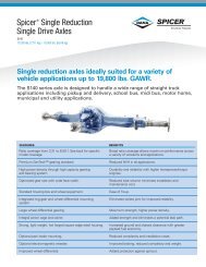
Typical <strong>Dana</strong> Single Reduction Tandem Axle<br />
Two design variations of tandem axles are included in this manual. The major difference is in the shaft spline design.<br />
Note: DS381 (P) axles manufactured after April 1985 are rated at 40,000 lbs.
Axle and Carrier Assembly Model Identification<br />
Drive Axle<br />
Gear i n g<br />
D - Forward Tan dem Axle<br />
R - Rear Tan dem Axle<br />
S - S ingle Redu ction<br />
D - Single Redu ction with Wheel<br />
Differential Lock<br />
T - Du al Ran ge<br />
P - Plan etary Dou ble Redu ction<br />
Example:<br />
D S = Forward Tandem Axle/S ingle Reduction<br />
R S = Rear Tan dem Axle/S ingle Reduction<br />
Note: Tags that do not include all the information shown here<br />
are older models (before May 1987).<br />
Spicer ®<br />
MODEL PART NO. RATIO<br />
MADE IN:<br />
CUST. PART NO.<br />
SPEC. SERIAL NO.<br />
2<br />
1<br />
3<br />
4<br />
CUST. PART NO.<br />
SPEC. SERIAL NO.<br />
MODEL PART NO. RATIO<br />
MADE IN:<br />
Data plate is located on<br />
the axle centerline<br />
Forward Axle (Side View) Rear Axle (Top View)<br />
General Information<br />
1 - Country or origin<br />
2 - Axle model identification<br />
3 - Specification number assigned to the axle built by Spicer. Identifies all component parts of the axle including special OEM<br />
requirements such as yokes or flanges.<br />
4 - OEM part number assigned to the axle build<br />
5 - Carrier assembly serial number assigned by the manufacturing plant<br />
6 - Axle gear ratio<br />
7 - Carrier assembly production or service part number<br />
Spicer ®<br />
5<br />
L u be Pu mp<br />
P = S tandard<br />
(P) = Optional<br />
6<br />
7<br />
Design Level<br />
Capacity (x 1000 lbs.)<br />
Example: 46 = 46,000 lbs.<br />
Spicer ®<br />
CUST. PART NO.<br />
SPEC. SERIAL NO.<br />
MODEL PART NO. RATIO<br />
MADE IN:<br />
2<br />
<strong>Service</strong> Procedure
General Information<br />
Part Identification<br />
Axle Housing Axle Shaft<br />
S picer®<br />
P T.<br />
NO.<br />
HSG. CAP.<br />
LBS.<br />
HSG. I.<br />
D.<br />
NO.<br />
HOUSING MADE<br />
IN<br />
1<br />
1 - ID Tag 2 - Axle shaft part number<br />
Axle Specification Number<br />
The complete axle is identified by the specification number stamped on the side of the axle housing. This number identifies all<br />
component parts of the axle as built by <strong>Dana</strong>, including special OEM requirements such as yoke or flange. In addition, some<br />
axles may include a metal identification tage.<br />
2<br />
3
Ring Gear and Pinion<br />
Note: Ring gear and drive pinion are matched parts and must<br />
be replaced in sets.<br />
1 - Part number<br />
2 - Number of ring gear teeth<br />
3 - Manufacturing numbers<br />
4 - Matching gear set number<br />
5 - Number of pinion teeth<br />
6 - Date code<br />
7 - Indicates genuine Spicer parts<br />
8 - Heat code<br />
85405<br />
EATON<br />
127381<br />
6-39<br />
JD77<br />
86<br />
1<br />
7<br />
SPICER<br />
7<br />
5<br />
R<br />
E<br />
C<br />
I<br />
P<br />
S<br />
8<br />
2<br />
7<br />
2<br />
1<br />
4<br />
7<br />
1<br />
2<br />
41-8<br />
1<br />
8<br />
8-41<br />
L2<br />
OF<br />
N7 1<br />
2<br />
127<br />
4<br />
0H<br />
17 G<br />
L7038<br />
8<br />
6<br />
3<br />
General Information<br />
3<br />
6<br />
G<br />
L7038<br />
4<br />
4<br />
<strong>Service</strong> Procedure
General Information<br />
Power Flow and Torque Distribution<br />
<strong>Dana</strong> Spicer tandem drive axles described in this publication are single reduction units designed primarily for highway or turnpike.<br />
They are also for a variety of other applications. This type of axle provides a vehicle with superior load carrying and roadability<br />
characteristics by dividing its work between two axles. The complete tandem assembly consists of two axles coupled by a power<br />
divider.<br />
Lube Pump System<br />
Power Divider<br />
In operation, the power divider accepts the torque from the vehicle driveline and distributes it equally to the two axles. This assembly<br />
is of the two-gear design consisting of an input shaft, inter-axle differential, output shaft and two constant-mesh helical<br />
gears. The inter-axle differential compensates for axle speed variations in the same way the wheel differential works between the<br />
two wheels of a single drive axle. This unit also acts as a central point in distribution of torque to the two axles. The power divider<br />
also includes a driver-controlled, air-operated lockout. When lockout is engaged, it mechanically prevents inter-axle differentiation<br />
for better performance under poor traction conditions.<br />
Gearing<br />
The gearing for each axle is of the spiral bevel design with drive pinion positioned at centerline of the ring gear. The differential<br />
and drive pinion are mounted on tapered roller bearings. The wheel differential is a 4 pinion and 2 side gear design.<br />
Lube Pump<br />
Tandem Axles with suffix letter "P" in Model No. are equipped with a lube pump to provide positive lubrication to the inter- axle<br />
differential and other power divider parts. This pump is operated by a drive gear engaged with the input shaft splines. When vehicle<br />
is moving in a forward direction, pressurized lube is delivered to the vital power divider parts. The pump lube system incorporates<br />
a magnetic strainer screen. To keep the system clean, the magnet traps minute particles and the screen blocks out large particles<br />
of foreign material.<br />
5
General Information<br />
Torque Distribution with Lockout Disengaged (Inter-axle Differential is Operation)<br />
Torque (power flow) from the vehicle driveline is transmitted to the input shaft and the inter-axle differential spider. At this point,<br />
the differential distributes torque equally to both axles. For the forward axle, torque is transmitted from the helical-side gear to the<br />
pinion helical gear, drive pinion, ring gear, wheel differential and axle shafts. For the rear axle, torque is transmitted from the output<br />
shaft side gear, through the output shaft, inter-axle driveline, to the drive pinion, ring gear, wheel differential and axle shafts.<br />
Torque Distribution with Lockout Engaged (inter-axle Differential is Not Operation)<br />
Input torque<br />
Lockout disengaged Drive is from differential<br />
through helical gears to<br />
forward gearing<br />
Inter-axle differential<br />
operating<br />
Drive is<br />
from differential<br />
through output<br />
shaft to<br />
rear gearing<br />
Torque is transmitted to both axles through inter-axle differential action.<br />
A lockout mechanism is incorporated in the power divider to enable the vehicle driver to lock out the inter-axle differential and<br />
provide maximum traction under adverse road conditions. In operation, an air cylinder (controlled by a cab-mounted valve) shifts<br />
a sliding clutch. To lock out inter-axle differential action, the clutch engages the helical-side gear and causes this gear, the input<br />
shaft and differential to rotate as one assembly. This action provides a positive drive to both axles. With Lockout engaged, torque<br />
is distributed to both-axles without differential action. The forward axle pinion and ring gear are driven by the helical side gear.<br />
The rear axle gearing is driven from the output shaft side gear and inter-axle driveline.<br />
Note: Varied road surface conditions can result in unequal torque distribution between the two axle assemblies.<br />
Lockout engaged<br />
Inter-axle differential<br />
not operating<br />
Input torque<br />
Drive is from<br />
output shaft side<br />
gear to rear<br />
gearing<br />
Drive is from input shaft<br />
through helical gears to<br />
forward gearing<br />
Torque is transmitted to both axles without inter-axle differential action.<br />
6<br />
<strong>Service</strong> Procedure
Eaton Single Reduction Tandem Drive Axles<br />
Differential Carrier Assembly Exploded View<br />
Forward Axle Carrier Assembly (Single Speed) with Diff. Lock<br />
Other Design Variations<br />
52 53 54 56 57 58 55 6 1 5<br />
RH<br />
59<br />
Axle Series D340, 380(P),400-P D341, 381(P), 401-P, 402(P), 403(P), 451-P<br />
Output Shaft Splines 16 16<br />
Side Gear End 16 16<br />
Output End<br />
Input Shaft Splines<br />
10 34<br />
Input End 15 44<br />
Diff End 36 36<br />
Helical Gears<br />
Drive Pinion Splines<br />
7 pitch 5 pitch<br />
Forward Axle 10 41<br />
Rear Axle<br />
Axle Shaft Side Gear Splines<br />
10 39<br />
D340- 16 D341- 39<br />
D380(P)- 16 D381(P), 402(P), 403(P)- 41<br />
D400(P)- 33 D401-P, 451-P- 33<br />
7<br />
4 2 3 1 9<br />
8<br />
DIFFERENTIAL<br />
& RING GEAR<br />
21 22 23 24 33 29 31 32 35 34 38 36 37 34 35 28 27 26 25<br />
30<br />
LH<br />
11<br />
10 13<br />
12<br />
1<br />
14<br />
19 15 16 17 18<br />
20<br />
7
Eaton Single Reduction Tandem Drive Axles<br />
Axle Series D340, 380(P), 400-P, D341, 381(P), 401-P, 402(P), 403 (P), 451-P<br />
76 77<br />
60 61 62<br />
63 64 65 66<br />
78 79 80 81 82 83<br />
39 31 40<br />
106<br />
41<br />
42<br />
43 45<br />
LUBE PUMP<br />
INTER-AXLE<br />
DIFFERENTIAL<br />
ASSEMBLY<br />
Note: Before Replacing Seals, Yokes, and Slingers, refer to the Repair and Replacement Instructions for interchangeability information.<br />
67 68<br />
91 93 92<br />
44 46 47 43 40<br />
104 103 95<br />
91<br />
69<br />
71<br />
70<br />
74 73 75<br />
84 85 86 88 89 90<br />
105<br />
87<br />
50<br />
48<br />
49 51<br />
94 97 98 99<br />
96 102<br />
70<br />
72<br />
100<br />
101<br />
8<br />
<strong>Service</strong> Procedure
Eaton Single Reduction Tandem Drive Axles<br />
1 - Differential carrier & bearing caps<br />
2 - Bearing capscrew<br />
3 - Flat washer<br />
4 - Lockwire<br />
5 - Dowel bushing<br />
6 - Bearing cap adjuster lock (RH)<br />
7 - Capscrew<br />
8 - Bearing cap adjuster lock (LH)<br />
9 - Cotter pin (LH)<br />
10 - Expansion plug (upper)<br />
11 -Expansion plug (lower)<br />
12 - Filler plug<br />
13 - Shift fork shaft<br />
14 - Carrier cover dowel pun<br />
15 - Shift unit mounting stud<br />
16 - Shift fork seal & spring assembly<br />
17 - Flat washer<br />
18 - Stud nut<br />
19 - Shift fork & roller assembly<br />
20 - Shift unit assembly<br />
21 - Sliding clutch<br />
22 - Differential bearing adjuster (RH)<br />
23 - Differential bearing cup (RH)<br />
24 - Differential bearing cone (RH)<br />
25 - Differential bearing adjuster (LH)<br />
26 - Differential bearing cup (LH)<br />
27 - Differential bearing cone (LH)<br />
28 - Differential case (plain half)<br />
29 - Differential case (flanged half)<br />
30 - Differential case capscrew<br />
31 - Ring gear & drive pinion<br />
32 - Bolt<br />
33 - Nut<br />
34 - Differential side gear<br />
36 - Side pinion<br />
37 - Side pinion thrust washer<br />
38 - Spider<br />
39 - Pinion pilot bearing<br />
40 - Pinion bearing cone<br />
41 - Pinion bearing spacer washer<br />
42 - Pinion bearing spacer<br />
43 - Pinion bearing cup<br />
44 - Pinion bearing cage<br />
45 - Pinion bearing cage shim<br />
46 - Lock washer<br />
47 - Bearing cage capscrew<br />
48 - Pinion helical gear<br />
49 - Outer pinion support bearing (one<br />
piece)<br />
50 - Pinion shaft end nut<br />
51 - Pinion nut spring pin<br />
52 - Output shaft nut<br />
53 - Output shaft washer<br />
54 - Rear bearing retaining washer<br />
55 - Axle housing cover<br />
56 - Output shaft oil seal<br />
57 - Bearing snap ring<br />
58 - Output shaft bearing<br />
59 - Filler plug<br />
60 - Output shaft<br />
61 - Output shaft bushing<br />
62 - Output shaft O-ring<br />
63 - Output shaft bearing cup<br />
64 - Output shaft bearing cone<br />
65 - Output shaft side gear<br />
66 - Side gear snap ring<br />
67 - Output shaft compression spring<br />
68 - Output shaft thrust bearing<br />
69 - Inter-axle differential assemble<br />
70 - Inter-axle differential case half<br />
71 - Case bolt<br />
72 - Case nut<br />
73 - Side pinion<br />
74 - Side pinion thrust washer<br />
75 - Spider<br />
76 - Helical side gear snap ring<br />
77- Helical side gear<br />
78 - Helical side gear bushing<br />
79 - Helical side gear thrust washer<br />
80 - Helical side gear “D” washer<br />
81 - Lockout sliding clutch<br />
82 - Input shaft<br />
83 - Input shaft bearing cone<br />
84 - Input shaft bearing cup<br />
85 - Input cover shim<br />
86 - Input bearing cover<br />
87 - Bearing cover capscrew<br />
88 - Input shaft oil seal<br />
89 - Input shaft nut washer<br />
90 - Input shaft nut<br />
91 - PDU carrier cover<br />
92 - Carrier cover capscrew<br />
93 - Lock washer<br />
94 - Pipe plug<br />
95 - Expansion plug<br />
96 - Magnetic filter screen<br />
97 - Pump gear & shaft assembly<br />
98 - Cover O-ring<br />
99 - Lube pump cover<br />
100 - Lock washer<br />
101 - Cover capscrew<br />
102 - Cover dowel pin<br />
103 - Pump drive gear<br />
104 - Drive gear locknut<br />
105 - Air-operated lockout assembly<br />
106 - Shift fork & push rod assembly<br />
9
Differential Carrier Assembly<br />
Rear Axle RS340, 341, 380, 400, 401, 402, 403, 451<br />
Eaton Single Reduction Tandem Drive Axles<br />
10 11 12 15 18 20 21 17 18 13 15 12 11 10<br />
2 4 3 6<br />
1 - Differential carrier & bearing caps<br />
2 - Bearing capscrew<br />
3 - Flat washer<br />
4 - Lockwire<br />
5 - Bearing cap adjuster lock<br />
6 - Cotter pin<br />
7 - Dowel bushing<br />
8 - Ring gear thrust screw<br />
9 - Thrust screw jam nut<br />
10 - Differential bearing adjuster<br />
11 - Differential bearing cup<br />
16 17 19 14 14<br />
5<br />
8 9 27 26 28 25 26 23 30 33<br />
6 5 1 1 22 13<br />
23 24 29 31 32<br />
12 - Differential bearing cone<br />
13 - Ring gear & drive pinion<br />
14 - Bolt and nut<br />
15 - Differential case (flanged half)<br />
16 - Differential case capscrew<br />
17 - Differential side gear<br />
18 - Side gear thrust washer<br />
19 - Side pinion<br />
20 - Side pinion thrust washer<br />
21 - Spider<br />
22 - Pinion pilot bearing<br />
23 - Pinion bearing cone<br />
24 - Pinion bearing spacer<br />
25 - Pinion bearing cage<br />
26 - Pinion bearing cup<br />
27 - Pinion bearing spacer washer<br />
28 - Pinion bearing cage shim<br />
29 - Bearing cage capscrew<br />
30 - Oil seal<br />
31 - Input yoke<br />
32 - Flat washer<br />
33 - Pinion nut<br />
10<br />
<strong>Service</strong> Procedure
Lubrication<br />
Lubrication<br />
The ability of a drive axle to deliver quiet, trouble free operation over a period of years is largely dependent upon the use of good<br />
quality gear lubricant in correct quantity. The most satisfactory results can be obtained by following the directions contained in<br />
this manual. The following lubrication instructions represent the most current recommendations from <strong>Dana</strong> <strong>Corporation</strong>.<br />
Approved Lubricants<br />
General—Gear lubrications acceptable under military specification (MILSPEC) MIL-L-2105D (Lubricating Oils, Gear, Multipurpose)<br />
are approved for use in <strong>Dana</strong> Spicer Drive Axles. The MIL-L-2105D specification defines performance and viscosity requirements<br />
for multigrade oils. It supersedes both MIL-L-2105B, MIL-L-2105C and cold weather specification MlL-L-l 0324A. This<br />
specification applies to both petroleum-based and synthetic based gear lubricants if they appear on the most current “Qualified<br />
Products List” (QPL-2105) for MIL-L-2105D.<br />
Note: The use of separate oil additives and/or friction modifiers are not approved in <strong>Dana</strong> Drive Axles.<br />
Synthetic based — Synthetic-based gear lubricants exhibit superior thermal and oxidation stability, and generally degrade at a<br />
lower rate when compared to petroleum-based lubricants. The performance characteristics of these lubricants include extended<br />
change intervals, improved fuel economy, better extreme temperature operation, reduced wear and cleaner component appearance.<br />
The family of Roadranger TM gear lubricants represents a premium quality synthetic lube which fully meets or exceeds the<br />
requirements of MIL-L-2105D. These products, available in both 75W-90 and 80 W-140, have demonstrated superior performance<br />
in comparison to others qualified under the MILSPEC, as demonstrated by extensive laboratory and field testing. For a<br />
complete list of Roadranger ® approved synthetic lubricants contact your local Roadranger representative. See back cover of this<br />
manual for appropriate phone number.<br />
Makeup Lube — Maximum amount of non-synthetic makeup lube is 100/o.<br />
Viscosity / Ambient Temperature Recommendations -The following chart lists the varies SAE Grades covered by MIL-L- 2105D<br />
and the associated ambient temperature range from each. Those SAE grades shown with an asterisk (*). are available in the<br />
Roadranger family of synthetic gear lubricants.<br />
The lowest ambient temperatures covered by this chart are -40°F and -40°C. Lubrication recommendations for those applications<br />
which consistently operate below this temperature range, must be obtained through tcontacting your local Roadranger epresentative.<br />
Grade Ambient Temperature<br />
75W - 40 F to -150 F (-40 C to -26 C)<br />
75W-80 - 40 F to 80 F (-40 C to 21 C)<br />
75W-90 - 40 F to 100 F (-40 C to 38 C)<br />
75W-140 - 40 F and above (-40 C and above)<br />
80W-90 - 40 F to 100 F (-40 C to -38 C)<br />
80W-140 - 40 F and above(-40 C and above)<br />
85W-140 - 40 F and above (-40 C and above)<br />
11
Lubrication<br />
Lube Change Intervals<br />
This product combines the latest manufacturing and part washing technology. When filled with an Roadranger approved synthetic<br />
lubricant at the factory, the initial drain is not required.<br />
Change the lubricant within the first 5,000 miles of operation when not using a Roadranger approved synthetic lubricant in either<br />
a new axle or after a carrier head replacement. Base subsequent lubricant changes on a combination of the following chart and<br />
user assessment of the application and operating environment.<br />
Severe <strong>Service</strong> Lubrication Change Intervals-Severe service applications are those where the vehicle consistently operates at or<br />
near its maximum GCW or GVW ratings, dusty or wet environments, or consistent operation on grades greater than 8%. For these<br />
applications, the ON/OFF HIGHWAY portion of the chart should be used. Typical applications are construction, logging, mining<br />
and refuse removal.<br />
Note: Remove metallic particles from the magnetic filler plug and drain plugs. Clean or replace the breather at each lubricant<br />
change.<br />
Guide Lines - Lube Change Intervals for Drive Axles<br />
Lubricant Type On-Highway Miles Maximum change Interval<br />
Changing Lube<br />
Draining<br />
Drain when the lube is at normal operating temperature. It will run freely and minimize the time necessary to fully drain the axle.<br />
Unscrew the magnetic drain plug on the underside of the axle housing and allow the lube to drain into a suitable container. Inspect<br />
drain plug for large quantities of metal particles. After initial oil change, these are signs of damage or extreme wear in the axle,<br />
and inspection of the entire unit may be warranted. Clean the drain plug and replace it after the lube has drained completely.<br />
Axles with Lube Pump: Remove the magnetic strainer from the power divider cover and inspect for wear material in the same<br />
manner as the drain plug. Wash the magnetic strainer in solvent and blow dry with compressed air to remove oil and metal particles.<br />
Exercise care to direct compressed air into safe area. Wear safety glasses.<br />
On/Off Highway Severe<br />
<strong>Service</strong> Miles<br />
Mineral Based 100,000 Yearly 40,000 Yearly<br />
Roadranger Approved<br />
Lubricant<br />
250,000 3 Years 100,000 Yearly<br />
CAUTION<br />
Maximum Change Interval<br />
12<br />
<strong>Service</strong> Procedure
Lubrication<br />
Filling<br />
Remove the filler hole plug from the center of the axle housing cover and fill the axle with approved lubricant until level with the<br />
bottom of the hole.<br />
Forward axles: Add two pints (0.94 liters) of lubricant through filler hole at the top of the differential carrier near the power divider<br />
cover.<br />
Oil Filler Hole at top of Differential Carrier Magnetic Strainer for Axle with Lube Pump<br />
Note: Lube fill capacities in the adjacent chart are good guidelines but will vary somewhat on the basis of the angle the axle is<br />
installed in a particular chassis. Always use the filler hole as the final reference. If lube is level with the bottom of the hole,<br />
the axle is properly filled.<br />
Axle Installation Angles<br />
Axles installed at angles exceeding 10 degrees or operated regularly in areas of continuous and lengthy grades may require standpipes<br />
to allow proper fill levels.<br />
For specific recommendations, contact your local Eaton representative. See back cover of this manual for phone numbers.<br />
Lube Capacities, <strong>Dana</strong> Housings<br />
Single Reduction Tandem Series Forward Axle Pints (liters) Rear Axle Pints (liters)<br />
380(P), 381(P), 400-P, 401-P 39 (18.5) 36 (17.0)<br />
402(P), 403(P),451-P 39 (18.5) 36 (17.0)<br />
Forward Axle: Add an additional 2 pints (0.94 liters) axle lubricant through filler hole at the top of differential carrier near the power<br />
divider cover.<br />
Capacities listed are approximate. The amount of lubricant will vary with angle of axle as installed in vehicle chassis.<br />
13
Wheel End Lubrication<br />
Lubrication<br />
Before operating the axle, the wheel hub cavities and bearings must be lubricated to prevent failure. When wheel ends are<br />
serviced, follow Eaton’s wheel end lubrication procedure before operating the axle.<br />
<strong>Dana</strong> Spicer axles may be equipped with either of two wheel end designs:<br />
Wheel ends with an oil fill hole.<br />
Wheel ends without an oil fill hole.<br />
Wheel Ends with an oil fill hole proceed as follows: (Fig. 1)<br />
1. Rotate the wheel end hub until the oil fill hole is up.<br />
2. Remove the oil fill plug.<br />
3. Pour 1/2 pint of axle sump lubricant into each hub through the wheel end fill hole.<br />
4. Install oil fill plug and tighten to specified torque.<br />
Fig. 1 Cutaway views of typical wheel and assemblies<br />
IMPORTANT<br />
Wheel End with Oil Fill Hole Wheel End without Oil Fill Hole<br />
WHEEL END<br />
OIL FILL HOLE<br />
PROPER<br />
LUBRICANT<br />
LEVEL<br />
PROPER<br />
LUBRICANT<br />
LEVEL<br />
LUBRICANT<br />
FLOW<br />
FROM SUMP<br />
14<br />
<strong>Service</strong> Procedure
Lubrication<br />
Wheel Ends without an oil fill hole proceed as follows: (Fig. 2)<br />
1. With axle level and wheel ends assembled, add lubricant through filler hole in axle housing cover until fluid is level with<br />
the bottom of filler hole.<br />
2. Raise the left side of the axle 6 inches or more. Hold axle in this position for one minute.<br />
3. Lower the left side.<br />
4. Raise the right side of the axle 6 inches or more. Hold axle in this position for one minute.<br />
5. Lower the right side.<br />
6. With axle on a level surface, add lubricant through housing cover oil filler hole until fluid is level with the bottom of the<br />
hole.<br />
Note: Axles without wheel end fill holes will require approximately 2.5 additional pints of lubricant to bring the lube level even with<br />
the bottom of fill hole.<br />
WITH AXLE ON LEVEL<br />
SURFACE FILL HOUSING<br />
WITH OIL TO BOTTOM OF PLUG<br />
TEMPERATURE SENSOR<br />
MOUNTING HOLE<br />
Fig. 2 Wheel end lubrication procedure<br />
OIL WILL<br />
RUN INTO<br />
WHEEL END<br />
OIL WILL<br />
RUN INTO<br />
WHEEL END<br />
TILT HOUSING SIDE TO SIDE, 1 MINUTE PER SIDE, THEN,<br />
RECHECK OIL LEVEL IN AXLE<br />
15
Cleaning, Inspection, Replacement<br />
General Information<br />
As the drive axle is disassembled, set all parts aside for thorough cleaning and inspection. Careful inspection will help determine<br />
whether parts should be reused. In many cases, the causes of premature wear or drive axle failure will also be revealed.<br />
Cleaning<br />
The differential carrier assembly may be steam-cleaned while mounted in the<br />
housing as long as all openings are tightly plugged. Once removed from its housing,<br />
do not steam clean differential carrier or any components. Steam cleaning at<br />
this time could allow water to be trapped in cored passages, leading to rust, lubricant<br />
contamination, and premature component wear. The only proper way to clean<br />
the assembly is to disassemble it completely. Other methods will not be effective<br />
except as preparatory steps in the process. Wash steel parts with ground or polished<br />
surfaces in solvent. There are many suitable commercial solvents available.<br />
Kerosene and diesel fuel are acceptable.<br />
Gasoline is not an acceptable solvent because of its extreme combustibiliy. It<br />
is unsafe in the workshop environment.<br />
Wash castings or other rough parts in solvent or clean in hot solution tanks using<br />
mild alkali solutions. If a hot solution tank is used, make sure parts are heated thoroughly,<br />
before rinsing.<br />
Rinse thoroughly to remove all traces of the cleaning solution. Dry parts immediately<br />
with clean rags.<br />
Lightly oil parts if they are to be reused immediately. Otherwise, coat with oil and<br />
wrap in corrosion-resistant paper. Store parts in a clean, dry place.<br />
Inspection<br />
WARNING<br />
Inspect steel parts for notches, visible steps or grooves created by wear. Look for<br />
pitting or cracking along gear contact lines. Scuffing, deformation or discoloration<br />
are signs of excessive heat in the axle, usually related to low lubricant levels or improper<br />
lubrication practices.<br />
Before reusing a gear set, inspect teeth for signs of excessive wear. Check tooth<br />
contact pattern for evidence of incorrect adjustment (see Adjustment Section for<br />
correct pattern). Inspect machined surfaces of cast or malleable parts. They must<br />
be free of cracks, scoring, and wear. Look for elongation of drilled holes, wear on<br />
surfaces machined for bearing fits and nicks or burrs in mating surfaces.<br />
Inspect fasteners for rounded heads, bends, cracks or damaged threads. The axle<br />
housing should be examined for cracks or leaks. Also look for loose studs or<br />
cross-threaded holes. Inspect machined surfaces for nicks and burrs.<br />
16<br />
<strong>Service</strong> Procedure
General Information<br />
Repair and Replacement<br />
IMPORTANT<br />
To achieve maximum value from an axle rebuild. Replace lower-cost parts, such as thrust washers, seals, etc. These items<br />
protect the axle from premature wear or loss of lubricants. Replacing these parts will not increase rebuild cost significantly.<br />
It is also important to replace other parts which display signs of heavy wear even though not cracked or broken. A significant<br />
portion of such a parts useful life has been expended and the damage caused, should the part fail, is far in excess of its cost.<br />
Steel Parts- Gear sets, input and output shafts, differential parts and bearings are not repairable. Worn or damaged parts should<br />
be discarded without hesitation. Also discard mating parts in some cases. Gear sets, for example, must be replaced in sets.<br />
Miscellaneous Parts - Seals and washers are routinely replaced. None of these parts can be reused if damaged. Fasteners using<br />
self-locking nylon patches may be reused if not damaged, but should be secured by a few drops of Loctite #277 on the threaded<br />
surface of the hole during installation and carefully torqued during installation.<br />
Axle Housings - Repairs are limited to removal of nicks or burrs on machined surfaces and the replacement of loose or broken<br />
studs.<br />
CAUTION<br />
Any damage which affects the alignment or structural integrity of the housing requires housing replacement. Repair by welding<br />
or straightening should not be attempted. This process can affect the housing heat treatment and cause it to fail completely<br />
when under load.<br />
Silicone Rubber Gasket Compound - For more effective sealing. <strong>Dana</strong> Spicer uses silicone rubber gasket compound to seal the<br />
majority of metal-to-metal mating surfaces.<br />
<strong>Dana</strong> Spicer includes gasket compound and application instructions in many repair parts kits.<br />
It is recommended that this compound be used in place of conventional gaskets. The compound will provide a more effective seal<br />
against lube and is easier to remove from mating surfaces when replacing parts.<br />
Seals, Yoke & Slinger <strong>Service</strong> Information<br />
During the 4th Quarter of 1990, new seals and yoke & slingers were used on the models in this publication. The new seals and<br />
slingers are noticeably different from the current seals and will affect interchangeability.<br />
The upgraded seals can be used on axles originally equipped with the old seals.<br />
<strong>Dana</strong> recommends the replacement of old yoke & slinger assemblies when the new seals are installed.<br />
The old yokes and slingers will work with the new seals, but new yoke and slinger assemblies provide maximum sealing protection<br />
and prevent premature seal wear due to poor yoke condition.<br />
New yoke and slinger assemblies cannot be used with the old seal design on the tandem forward axles.<br />
New yoke and slinger assemblies can be used with the old seal on the tandem rear pinions.<br />
Yoke Assembly & Oil Seal Kits contain oil seal, yoke & slinger and instructions.<br />
Most non-<strong>Dana</strong> aftermarket seals will not be compatible with the new <strong>Dana</strong> Yoke and Slinger assemblies.<br />
<strong>Dana</strong> Spcier recommends the use of special installation tools conveniently packaged in one single kit (listed below).<br />
Refer to <strong>Dana</strong> parts Book AXIP-0089 and Eaton Bulletin 90-06 for additional information.<br />
Seal Driver Installation Kit 272139<br />
126917 Driver (Rear Axle Pinion)<br />
127787 Adapter (use with 126917 Driver for Forward Axle Input)<br />
127786 Driver (Forward Axle Output)<br />
17
Wheel Bearing Adjustment<br />
Special Instructions<br />
Adjustments<br />
Never work under a vehicle supported by only a jack. Always support vehicle with stands. Block the wheels and make sure<br />
the vehicle will not roll before releasing the brakes.<br />
Procedure - Wheel End Seal<br />
1. Remove:<br />
The outer bearing and wheel.<br />
The inner bearing.<br />
The oil seal or grease retainer and discard.<br />
The old wear sleeve (2-piece design only) with a ball peen hammer and discard.<br />
Wheel end seals can be easily damaged during handling. Leave the seal in its package until installation to prevent damage<br />
or contamination.<br />
Do not cut through the old wear sleeve. Damage to the housing may result.<br />
2. Inspect:<br />
The spindle journal and hub bore for scratches or burns. Recondition with emery cloth as required.<br />
Note: Deep gouges can be repaired by filling gouge with hardened gasket and smoothing with emery cloth.<br />
3. Clean:<br />
The hub cavity and bearing bores before reassembly. Be sure to remove contaminants from all recesses and corners.<br />
The bearings thoroughly with solvent and examine for damage. Replace damaged or worn bearings.<br />
Before installation, lubricate with the same lubricant used in the axle sump.<br />
The inner bearing.<br />
The wheel seal following the directors provided by the seal supplier.<br />
IMPORTANT<br />
Always use the seal installation tool specified by the seal manufacturer. Using an improper tool can distort or damage<br />
the seal and cause premature seal failure.<br />
Procedure - Wheel Bearing Adjustment<br />
WARNING<br />
IMPORTANT<br />
CAUTION<br />
1. Identify the wheel nut system being installed. Three systems are available:<br />
Three piece Dowel-type wheel nut system -Fig.1<br />
Three piece Tang-type wheel nut system - Fig.2<br />
18<br />
<strong>Service</strong> Procedure
Adjustments<br />
Four piece Tang/Dowel type wheel nut system - Fig.3<br />
Do not mix spindle nuts and lock washers from different systems. Mixing spindle nuts and lock washers can cause wheel<br />
separation.<br />
Note: The lock washer for a four piece-dowel-type wheel system is thinner than the lock washer for a three piece tang-type<br />
wheel nut system and is not designed to bear against the inner nut.<br />
Fig 1<br />
Outer nut<br />
(P/N 119881)<br />
Inner nut<br />
(P/N 119882)<br />
Dowel Pin<br />
Dowel-type Lock<br />
Washer (P/N 119883)<br />
Outer nut<br />
(P/N 11249)<br />
WARNING<br />
Inner nut<br />
(P/N 11249)<br />
Tang-type lock washer<br />
(P/N 119883) 0.123" thick<br />
2. Inspect the spindle and nut threads for corrosion and clean thoroughly or replace as required.<br />
Note: Proper assembly and adjustment is not possible if the spindle or nut threads are corroded.<br />
lnspect the tang-type washer (if used). Replace the washer if the tangs are broken, cracked, or damaged.<br />
3. Install the hub and drum on the spindle with care to prevent damage or distortion to the wheel seal.<br />
A wheel dolly is recommended during installation to make sure that the wheel seal is not damaged by the weight of the<br />
hub and drum. Never support the hub on the spindle with just the inner bearing and seal. This can damage the seal and<br />
cause premature failure.<br />
Completely fill the hub cavity between the inner and outer bearing races with the same lubricant used in the axle sump.<br />
4. Before installation, lubricate the outer bearing with the same lubricant used in the axle sump.<br />
Note: Lubricate only with clean axle lubricant of the same type used in the axle sump. Do not pack the bearing with grease<br />
before installation. Grease will prevent the proper circulation of axle lubricant and may cause wheel seal failure.<br />
5. Install the outer bearing on the spindle.<br />
Install the inner nut on the spindle.<br />
Tighten the inner nut to 200 lbs. ft. (271 N.M.) while rotating the wheel hub.<br />
Fig 2<br />
CAUTION<br />
CAUTION<br />
Outer nut<br />
(P/N 119881)<br />
Tang-type lock<br />
washer (P/N 129132)<br />
.0478" thick<br />
Dowel-type lock<br />
washer (P/N 119883)<br />
Inner nut<br />
(P/N 119882)<br />
Dowel pin<br />
Never use an impact wrench to adjust wheel bearings. A torque wrench is required to assure that the nuts are property<br />
Fig 3<br />
19
tightened.<br />
6. Back-off the inner nut one full turn. Rotate the wheel hub.<br />
7. Re-tighten the inner nut to 50 lbs. ft. (68 N.M.) while rotating the wheel hub.<br />
8. Back-off the inner nut exactly 1/4 turn.<br />
Adjustments<br />
Note: This adjustment procedure allows the wheel to rotate freely with 0.001"-0.005" (0.025mm to 0.1 27mm) end-play.<br />
9. Install the correct lock washer for the wheel nut system being used.<br />
Procedure - Three piece tang-type lock washer system (see Fig. 2).<br />
1. Install the Tang-type lock washer on the spindle.<br />
Never tighten the inner nut for alignment. This can preload the bearing and cause premature failure.<br />
2. Install the outer nut on the spindle and tighten to 250 lbs. ft. (339 N.M.).<br />
3. Verify end-play (see End Play Verification Procedure)<br />
4. After verifying end play, secure wheel nuts by bending one of the locking washer tangs over the outer wheel nut and another<br />
tang over the inner wheel nut as shown in Figure 4. (below)<br />
Bend two tangs…<br />
one over inner nut<br />
and one over<br />
outer nut<br />
Outer nut<br />
Procedure - Three piece dowel-type lock washer system (see Fig. 1)<br />
1. Install the Dowel-type lock washer on the spindle.<br />
IMPORTANT<br />
Lockwasher<br />
Note: If the dowel pin and washer are not aligned, remove washer, turn it over and reinstall. If required, loosen the inner nut<br />
just enough for alignment.<br />
IMPORTANT<br />
Never tighten the inner nut for alignment. This can preload the bearing and cause premature failure.<br />
Spindle<br />
Inner nut<br />
20<br />
<strong>Service</strong> Procedure
Adjustments<br />
2. Install the outer nut on the spindle and tighten to 350 lbs. ft. (475 N.M.).<br />
3. Verify end-play (see End Play Verification Procedure)<br />
Procedure - Four piece tang/dowel-type lock washer system (see Fig. 3)<br />
1. First, install the Dowel-type lock washer on the spindle.<br />
Note: If the dowel pin and washer are not aligned, remove washer, turn it over and reinstall. If required loosen the inner nut<br />
just enough for alignment.<br />
Never tighten the inner nut for alignment. This can preload the bearing and cause premature failure.<br />
2. Install the Tang-type lock washer on the spindle.<br />
3. Install the outer nut on the spindle and tighten to 250 lbs. ft. (339 N. M.)<br />
4. Verify end-play (see End Play Verification Procedure)<br />
5. After verifying end play, secure the outer nut by bending two opposing (180° apart) tangs of the locking washer over the outer<br />
nut as shown in Figure 5.<br />
Procedure - Install<br />
1. Install a new gasket at axle shaft flange.<br />
2. Install axle shaft.<br />
Bend two tangs<br />
over outer nut<br />
3. Install axle flange nuts and tighten to specified torque.<br />
4. Lubricate axle wheel ends (see Wheel End Lubrication Procedure)<br />
Procedure - End Play Verification Procedure<br />
Outer nut<br />
IMPORTANT<br />
Figure 5<br />
Lockwasher<br />
Inner nut<br />
Dowel pin<br />
1. Verify that end-play meets specification using a dial indicator. An indicator with 0.001” (0.03 mm) resolution is required.<br />
Spindle<br />
21
Wheel end play is the free movement of the tire and wheel assembly along the spindle axis.<br />
2. Attach a dial indicator with its magnetic base to the hub or brake drum as shown below:<br />
End Play Adjustment<br />
with Tire & Wheel<br />
Assembly<br />
Adjustments<br />
3. Adjust the dial indicator so that its plunger or pointer is against the end of the spindle with its line of action approximately<br />
parallel to the axis of the spindle.<br />
4. Grasp the wheel assembly at the 3 o’clock and 9 o’clock positions. Push the wheel assembly in and out while oscillating it to<br />
seat the bearings. Read bearing end play as the total indicator movement.<br />
If end play is not within specification, readjustment is required.<br />
Procedure - End Play Readjustment Procedure<br />
CAUTION<br />
With indicator mounted at bottom,<br />
Push/Pull at sides of drum<br />
End Play Adjustment<br />
with Wheel hub<br />
1. Excessive End Play - If end play is greater than.005” (.127 mm), remove the outer nut and pull the lock washer away from<br />
the inner nut, but not off the spindle. Tighten the inner nut to the next alignment hole of the dowel-type washer (if used).<br />
Reassemble the washer and torque the outer nut. Verify end play with a dial indicator.<br />
2. Insufficient End Play - If end play is not present, remove the outer nut and pull the lock washer away from the inner nut, but<br />
not off the spindle. Loosen the inner nut to the next adjustment hole of the dowel-type washer (if used). Reassemble the washer<br />
and re-torque the outer nut. Verify end play with a dial indicator.<br />
3. Fine Tuning the End Play - If, after performing the readjustment procedures, end play is still not within the.001”-.005” (.025<br />
mm to.127 mm) range, disassemble and inspect the components. If parts are found to be defective, replace the defective<br />
parts, reassemble and repeat wheel bearing adjustment procedure. Verify end play with a dial indicator.<br />
22<br />
<strong>Service</strong> Procedure
Adjustments<br />
Differential Carrier Adjustments<br />
Adjustments help provide optimum axle life and performance by correctly positioning bearings and gears under load. The tandem<br />
axles covered in this manual require the following adjustments:<br />
Bearing Preload: This adjustment is performed for both pinion and differential bearings. It maintains proper gear alignments by<br />
creating correct bearing cone and cup relationships for free rotation under load. The pinion pilot bearing does not require a preload<br />
adjustment.<br />
Ring Gear Tooth Contact: This adjustment positions ring gear and pinion for best contact under load. Correct adjustment distributes<br />
torque evenly over gear teeth and helps maximize gear set Iife.<br />
Input Shaft End Play (Forward Axles): This adjustment controls gear mesh in the inter-axle differential. Proper adjustment helps<br />
maximize life of all power divider parts.<br />
Adjust Input Shaft End Play<br />
Specifications: Input shaft end play requirements will vary with operating conditions, mileage and rebuild procedures. These variations<br />
are shown in the following chart.<br />
Input Shaft End Play<br />
New or Rebuild with new parts: 0.003" to 0.007".<br />
Rebuild with reused parts: 0.013" to 0.017".<br />
Note: Because of manufacturing variations in individual parts, correctly adjusted end play could vary 0.010", after the unit is rotated.<br />
Acceptable End Play Tolerances when measuring as a regular maintenance procedure with axle in truck.<br />
Up to 0.060" with over 100,000 miles or 1 year service off-road.<br />
Up to 0.040" with less than 100,000 miles or 1 year service on- road.<br />
Note: If end play exceeds limits, disassemble power divider and replace worn parts.<br />
Procedure - Measure and Adjust End Play<br />
1.<br />
IMPORTANT<br />
In September 1988, a Spring and a Thrust Button between the input and output shafts. End play tolerances are the same<br />
for axles with or without this Spring and Button. However, end play measurement procedure is different than described<br />
below. Refer to <strong>Service</strong> Bulletin Supplement at back of this manual for procedure variances.<br />
With power divider assembled to differential carrier, measure end play with dial indicator positioned at yoke end of input shaft.<br />
Move input shaft axially and measure end play. If end play is not correct (see chart), adjust as follows.<br />
2. Remove input shaft nut, flat washer and yoke. Remove bearing cover cap screws and lock washers. Remove cover and shim<br />
pack.<br />
3. To increase end play, add shims:<br />
Desired end play: 0.003" to 0.007"<br />
Measured endplay (Step 1): 0.001" - 0.001"<br />
Add shims to provide desired end play : 0.002" to 0.006"<br />
23
4. To decrease end play, remove shims:<br />
Measured end play (Step 1): 0.015" - 0.015"<br />
Desired end play: 0.003" to 0.007"<br />
Remove shims to provide desired end play : 0.012" to 0.008"<br />
Adjustments<br />
5. To reassemble input shaft, install the adjusted shim pack and bearing cover. Install cap screws and lock washers. Torque<br />
screws to 75-85 ft. lbs. (101-115 N.m).<br />
Pry bar<br />
Measuring End Play with Dial Indicator<br />
Note: If difficulty is experienced in achieving correct torque on the input yoke nut, torque the nut with truck on the ground<br />
and axle shafts installed.<br />
6. Install yoke, flat washer and nut. Tighten nut snugly. Tap end of input shaft lightly to seat bearings.<br />
7. Measure input shaft end play with dial indicator. If end play is still incorrect, repeat Steps 2 through 6.<br />
8. With end play correct, seal shim pack to prevent lube leakage, then torque input shaft nut and cover cap screws (see chart).<br />
Note: When power divider has been disassembled and reassembled, it may be desirable to adjust end play by measuring bearing<br />
cover clearance and calculating shim pack size. For procedures, see page 39.<br />
Torque Chart<br />
U-bracket<br />
Lift up on<br />
pry bar to<br />
compress<br />
input shaft.<br />
Dial indicator<br />
Input shaft<br />
ft. lbs. N.m<br />
Input Shaft Nut<br />
1 5/8 - 18 780-960 1057 - 1301<br />
*M42 x 1.5 840 - 1020 1140 - 1383<br />
Bearing Cover Capscrew<br />
1/2 - 13 75 - 85 101 - 115<br />
*Metric Nut used on Axles produced after 1-3-95<br />
24<br />
<strong>Service</strong> Procedure
Adjustments<br />
Pinion Bearing Preload<br />
Special Instructions<br />
Most late model axles are provided with a “press-fit” outer bearing on the drive pinion. Some of the early model axles use an outer<br />
bearing which slips over the drive pinion. Procedures for adjusting both types of pinion bearing design are contained in this section.<br />
Procedure - Adjust Pinion Bearing Preload for Axles with “Press-fit” Outer Pinion Bearings<br />
1. Trial Build-up<br />
Assemble pinion bearing cage, bearings and spacer (without drive pinion or oil seal). Center bearing spacer between two bearing<br />
cones.<br />
Assemble these Parts for<br />
Trial Build-up.<br />
Inter<br />
Inner bearing<br />
bearing cone<br />
cone<br />
Inter<br />
Inner bearing<br />
bearing cup<br />
cup<br />
Bearing<br />
Bearing spacer<br />
spacer (variable)<br />
(variable)<br />
Outer<br />
bearing Outer<br />
cup bearing<br />
cup<br />
Bearing<br />
Bearing cage<br />
cage<br />
Outer<br />
bearing Outer<br />
cone bearing<br />
cone<br />
Note: When new gear set or pinion bearings are used, select nominal size spacer from the specification chart below. If original<br />
parts are used, use spacer removed during disassembly.<br />
2. With the bearings well lubricated, place the assembly in the press. Position sleeve so that load is applied directly to the backface<br />
of the outer bearing cone.<br />
Cage in Press<br />
to Check Bearing<br />
Preload.<br />
Press<br />
Press Ram ram<br />
Sleeve Must<br />
Sleeve Apply must Pressure<br />
apply<br />
To<br />
pressure<br />
Back Face<br />
to<br />
back face of<br />
outer Of bearing Outer<br />
cone Bearing Cone<br />
Spring Spring scale<br />
Scale<br />
25
Adjustments<br />
3. Apply press load (see chart below) to the assembly and check rolling torque. Wrap soft wire around the bearing cage, attach<br />
spring scale and pull. Preload is correct when torque required to rotate the pinion bearing cage is from 10-20 in. lbs.. This<br />
specification is translated into spring scale readings in the chart below.<br />
Specifications for Pinion Bearing Trial Build-up Preload Test (“Press-fit” Outer Pinion Bearings)<br />
Nominal Bearing Spacer<br />
Thickness<br />
Press<br />
Loads<br />
Spring Scale Reading (without pinion<br />
seal) (for 10-20 in. lbs. torque) (1.1-<br />
2.3 N.m)<br />
Axle Models<br />
Forward Axles<br />
in. mm Tons Metric Tons lbs. Kgs.<br />
D340,<br />
400-P<br />
380(P), 0.638 16.21 13.5 - 15.5 122- 140 3-7 2-3<br />
D341, 381, (P),<br />
401-P, 402(P),<br />
403(P), 451-P<br />
0.496 12.60 17 - 19 154 - 172 3-7 1.4-<br />
32<br />
Rear Axles 0.638 16.21 14 - 15 127 - 136 4-8 18-<br />
36<br />
4. If necessary, Adjust Pinion Bearing Preload by changing the pinion bearing spacer. A thicker spacer will decrease preload. A<br />
thinner spacer will increase preload.<br />
IMPORTANT<br />
Once correct bearing preload has been established, note the spacer size used. Select a spacer<br />
0.001” larger for use in the final pinion bearing cage assembly. The larger spacer compensates for<br />
slight “growth” in the bearings which occurs when they are pressed on the pinion shank. The trial<br />
build-up will result in proper pinion bearing preload in three of four cases.<br />
Do not assume that all assemblies will retain proper preload once bearings are pressed on pinion<br />
shank. Final preload test must be made in every case.<br />
26<br />
<strong>Service</strong> Procedure
Adjustments<br />
Final Pinion Bearing Preload Test<br />
Procedure -<br />
1. Assemble the complete pinion bearing cage unit as recommending the assembly section of this manual.<br />
Measuring Bearing Preload with Pinion in Vise<br />
Note: Forward axle pinion is equipped with helical gear. For easier disassembly during bearing adjustment procedure, use a<br />
dummy yoke (if available) in place of helical gear.<br />
2. Apply clamp load to the pinion bearing cage assembly. Either install the yoke (or helical gear) and torque the pinion nut to<br />
specifications or use a press to simulate nut torque (see chart below).<br />
Vise Method - If the yoke and nut are used, mount the assembly in a vise, clamping yoke firmly.<br />
Press Method - If a press is used, position a sleeve or spacer so that load is applied directly to the back-face of the outer<br />
bearing cone.<br />
Measuring Bearing Preload with Pinion in Press<br />
3. Measure Pinion Bearing Preload - Use a spring scale to test the assembly rolling torque. To use the spring scale, wrap soft<br />
wire around the bearing cage, attach the scale and pull. Preload is correct when torque required to rotate the pinion bearing<br />
cage is from 15 to 35 in. lbs.. This specification is translated into spring scale readings in the chart below.<br />
27
Final Pinion Bearing Preload Test<br />
Axle Model<br />
Forward Axle<br />
Nut Torque ft. lbs. (N.m) Press Load- Tons (Metric<br />
tons)<br />
D340, 380(P), 400-P 560 - 700 (759 - 949) Self<br />
Locking Nut<br />
D341, 381(P), 401-P, 402(P),<br />
403(P), 451-P<br />
780 - 960 (1057-1301) Self<br />
Locking Nut<br />
840-1020 (1140-1383) Metric<br />
Nut<br />
840* (1139) Slotted Nut and<br />
role pin<br />
13.5 - 15.5 (12.2 - 14.0) 5-12 (2.3-5.4)<br />
17 - 19 (15.4 - 17.2) 5-12 (2.3-5.4)<br />
17 - 19 (15.4 - 17.2) 5-12 (2.3-5.4)<br />
17 - 19 (15.4 - 17.2) 5-12 (2.3-5.4)<br />
Rear Axle (All models) 560-700 (759-949) 14-15 (12.7-13.6) 6-14 (2.7-6.4)<br />
Adjustments<br />
Spring Seal Reading (without<br />
pinion seal)- lbs (kg)<br />
*Torque nut to 840 ft-lbs. (1 139 N.m), Then continue tightening nut to align nut slot to nearest hole in pinion shank.<br />
4. Adjust Pinion Bearing Preload - If necessary, adjust pinion bearing preload. Disassemble the pinion bearing cage as recommended<br />
in this -manual and change the pinion bearing spacer. A thicker spacer will decrease preload. A thinner spacer will<br />
increase preload.<br />
IMPORTANT<br />
Use the correctly sized spacer. Do not use shim stock or grind spacers. These practices can lead to<br />
loss of bearing preload and gear or bearing failure.<br />
28<br />
<strong>Service</strong> Procedure
Adjustments<br />
Adjust Pinion Bearing Preload for Axles with "Slip-fit" Outer Pinion Bearings<br />
Procedure -<br />
1. Lubricate bearings and assemble the drive pinion, bearings, and pinion bearing cage as recommended in the assembly section<br />
of this manual. Use the pinion bearing spacer removed from the axle during disassembly. If the original spacer cannot be<br />
used, install the nominal spacer recommended in the adjacent chart.<br />
Nominal Pinion Bearing Spacers<br />
Axle Model Spacer Thickness in (mm)<br />
Forward Axle<br />
D340, 380(P), 400-P 0.638 (16.205)<br />
D341, 381(P), 401-P, 402(P), 403(P), 0.492 (12.497)<br />
451-P<br />
Rear Axle (all models) 0.638 (16.205)<br />
Note: Forward axle pinion is equipped with helical gear, For easier disassembly during bearing adjustment procedure, use a<br />
dummy yoke (if available) in place of helical gear.<br />
2. Apply clamp load to the pinion bearings. Install the yoke (or helical gear) and torque the nut to specification or use a press to<br />
simulate nut torque by applying pressure to the assembly (see chart below).<br />
Vise Method - If the yoke and nut are used, mount the assembly in a vise, clamping yoke firmly.<br />
Press Method - If a press is used, position a sleeve or spacer so that load is applied directly to the back-face of the outer<br />
bearing cone.<br />
Measuring Bearing Preload with Pinion in Vise<br />
3. Measure Pinion Bearing Preload - Use a spring scale to test the assembly rolling torque. To use the spring scale, wrap soft<br />
wire around the bearing cage, attach the scale and pull. Preload is correct when torque required to rotate the pinion bearing<br />
cage is from 15 to 35 in. lbs. This specification is translated into spring scale readings in the chart below.<br />
29
Measuring Bearing Preload with Pinion in Press<br />
Adjustments<br />
4. Adjust Pinion Bearing Preload - If necessary, adjust pinion bearing preload. Disassemble the pinion bearing cage as recommended<br />
in this manual and change the pinion bearing spacer. A thicker spacer will decrease preload. A thinner spacer will<br />
increase preload.<br />
Use the correctly sized spacer, Do not use shim stock or grind spacers. These practices can lead to<br />
loss of bearing preload and gear or bearing failure.<br />
Final Pinion Bearing Preload Test (Slip fit outer pinion bearings)<br />
Axle Model<br />
Forward Axle<br />
Nut Torque ft. lbs (N.m) Press Load- Tons (Metric<br />
tons)<br />
D340, 380(P), 400-P 560 - 700 (759 - 949) Self<br />
Locking Nut<br />
D341, 381(P), 401-P, 402(P),<br />
403(P), 451-P<br />
780 - 960 (1057-1301) Self<br />
Locking Nut<br />
840-1020 (1140-1383) Metric<br />
Nut<br />
840* (1139) Slotted Nut and<br />
role pin<br />
IMPORTANT<br />
13.5 - 15.5 (12.2 - 14.0) 5-12 (2.3-5.4)<br />
17 - 19 (15.4 - 17.2) 5-12 (2.3-5.4)<br />
17 - 19 (15.4 - 17.2) 5-12 (2.3-5.4)<br />
17 - 19 (15.4 - 17.2) 5-12 (2.3-5.4)<br />
Rear Axle (All models) 560-700 (759-949) 14-15 (12.7-13.6) 6-14 (2.7-6.4)<br />
Spring Seal Reading (without<br />
pinion seal)- lbs (kg)<br />
*Torque nut to 840 ft-lbs. (1 139 N.m), Then continue tightening nut to align nut slot to nearest hole in pinion shank.<br />
30<br />
<strong>Service</strong> Procedure
Adjustments<br />
Differential Bearing Preload and Ring Gear Backlash Adjustment<br />
Special Instructions<br />
Correct differential bearing preload insures proper location of these bearings under load and helps position the ring gear for proper<br />
gear tooth contact.<br />
Procedure - Adjust Diff. Bearing Preload<br />
1. Lubricate differential bearings.<br />
IMPORTANT<br />
When installing bearing caps and adjuster, exert<br />
care not to cross threads.<br />
2. Install adjusters and bearing caps. Tighten bearing cap<br />
screws finger-tight. If this is difficult, use a hand wrench.<br />
Note: Ring gear position for rear axle is illustrated.<br />
3. Loosen the bearing adjuster on the same side as the ring<br />
gear teeth until its first thread is visible.<br />
4. Tighten the bearing adjuster on the back-face side of the<br />
ring gear until there is no backlash.<br />
This can be tested by facing the ring gear teeth and pushing<br />
the gear away from the body while gently rocking the<br />
gear from side to side. There should be no free movement.<br />
Rotate the ring gear and check for any point where the<br />
gear may bind. If such a point exists, loosen and re-tighten<br />
the back side adjuster. Make all further adjustments<br />
from the point of tightest mesh.<br />
5. At teeth side of ring gear, tighten adjuster until it contacts<br />
the bearing cup. Continue tightening adjuster two or three<br />
notches and this will preload bearings and provide back-<br />
lash.<br />
6. Measure backlash with a dial indicator.<br />
USED GEARING — Reset to backlash recorded before disassembly.<br />
NEW GEARING — Backlash should be between 0.006”<br />
and 0.016”.<br />
If backlash is incorrect, proceed as described below to readjust.<br />
Procedure - Adjust Ring Gear Backlash<br />
1. To add backlash: Loosen the adjuster on the teeth side of<br />
the ring gear several notches. Loosen the opposite adjuster<br />
one notch. Return to adjuster on teeth side of the ring<br />
gear and tighten adjuster until it contacts the bearing cup.<br />
Continue tightening the same adjuster 2 or 3 notches. Recheck<br />
backlash.<br />
2. To remove backlash: Loosen the adjuster on the teeth side<br />
of the ring gear several notches. Tighten the opposite adjuster<br />
one notch. Return to adjuster on teeth side of ring<br />
gear and tighten adjuster until it contacts the bearing cup.<br />
Continue tightening the same adjuster 2 or 3 notches. Recheck<br />
backlash.<br />
One One<br />
Notch notch<br />
Lugs<br />
3. Moving adjuster one notch is the movement of the lead<br />
edge of one adjuster lug to the lead edge of the next lug<br />
past a preselected point.<br />
31
Adjustments<br />
Ring Gear and Pinion Tooth Contact<br />
Note: Rear axle gearing is shown in the following instructions. Correct tooth contact patterns and adjustments are the same for<br />
forward and rear axles.<br />
Check Tooth Contact Pattern (NEW GEAR)<br />
Paint twelve ring gear teeth with marking compound and roll the gear to obtain a contact pattern. The correct pattern is well-centered<br />
on the ring gear tooth with lengthwise contact clear of the toe. The length of the pattern in an unloaded condition is approximately<br />
one-half to two-thirds of the ring gear tooth in most models and ratios.<br />
Face<br />
width<br />
Correct Pattern New Gearing<br />
Tooth<br />
depth Could vary in length.<br />
Pattern should cover<br />
1/2 tooth or more<br />
(face width).<br />
Heel<br />
Top land<br />
Root<br />
Toe<br />
Pattern should be<br />
evenly centered<br />
between tooth<br />
top land and root.<br />
Pattern should be clear of tooth toe.<br />
Check Tooth Contact Pattern (USED GEAR)<br />
Used gearing will not usually display the square, even contact pattern found in new gear sets. The gear will normally have a “pocket”<br />
at the toe-end of the gear tooth which tails into a contact line along the root of tooth. The more use a gear has had, the more<br />
the line becomes the dominant characteristic of the pattern. Adjust used gear sets to display the same contact pattern observed<br />
before disassembly. A correct pattern is clear of the toe and centers evenly along the face width between the top land and root.<br />
Otherwise, the length and shape of the pattern are highly variable and is considered acceptable as long as it does not run off the<br />
tooth at any point.<br />
Correct Pattern Used Gearing<br />
Pocket may be<br />
extended.<br />
Pattern along<br />
the face width<br />
could be longer.<br />
32<br />
<strong>Service</strong> Procedure
Adjustments<br />
Adjust Tooth Contact Patterns<br />
If necessary, adjust the contact pattern by moving the ring gear and drive pinion. Ring gear position controls the backlash. This<br />
adjustment moves the contact pattern along the face width of the gear tooth, Pinion position is determined by the size of the pinion<br />
bearing cage shim pack. It controls contact on the tooth depth of the gear tooth. These adjustments are interrelated. As a result,<br />
they must be considered together even though the pattern is altered by two distinct operations. When making adjustments, first<br />
adjust the pinion, then the backlash. Continue this sequence until the pattern is satisfactory.<br />
Adjust Pinion Position<br />
If the gear pattern shows incorrect tooth depth contact, change drive pinion position by altering the shim pack. Used gears should<br />
achieve proper contact with the same shims removed from the axle at disassembly.<br />
INCORRECT PATTERN<br />
Move pinion toward<br />
ring gear.<br />
Pattern too close to tooth top land and off center.<br />
If the pattern is too close to the top land of the gear tooth, remove pinion shims. If the pattern is too close to the root of the gear<br />
tooth, add pinion shims. Check ring gear backlash after each shim change and adjust if necessary to maintain the 0.006” to 0.016”<br />
specifications.<br />
Adjust Backlash<br />
If the gear pattern shows incorrect face width contact, change backlash.<br />
INCORRECT PATTERN<br />
Move ring gear<br />
away from pinion<br />
to increase backlash.<br />
Pattern too close to edge of tooth toe.<br />
INCORRECT PATTERN<br />
Move pinion<br />
away from<br />
ring gear.<br />
Pattern too close or off tooth root.<br />
INCORRECT PATTERN<br />
Move ring gear<br />
toward pinion<br />
to decrease<br />
backlash.<br />
Pattern too far along tooth toward tooth heel.<br />
With the pattern concentrated at the toe (too far down the tooth), add backlash by loosening the bearing adjuster on the teeth side<br />
of ring gear several notches. Loosen the opposite adjuster one notch. Return to adjuster on teeth side of ring gear and tighten<br />
adjuster until it contacts the bearing cup. Continue tightening the same adjuster 2 or 3 notches. Recheck backlash.<br />
If the pattern is concentrated at the heel (too far up-the tooth), remove backlash by loosening the bearing adjuster on the teeth<br />
side of ring gear several notches. Tighten the opposite adjuster one notch. Return to adjuster on teeth side of ring gear and tighten<br />
adjuster until it contacts the bearing cup. Continue tightening the same adjuster 2 or 3 notches. Recheck backlash.<br />
33
Fastener Tightening Specifications<br />
Specifications are for all axle models unless specified otherwise.<br />
Fastener Tightening Specifications<br />
34<br />
<strong>Service</strong> Procedure
Fastener Tightening Specifications<br />
<strong>Dana</strong> Single Reduction Tandem Models<br />
D340, 380(P), 400-P D341, 381 (P), 401-P, 402(P), 403(P), 451-P<br />
Correct tightening torque values are extremely important to assure long <strong>Dana</strong> Axle life and dependable performance. Under-tightening<br />
of attaching parts is just as harmful as over-tightening.<br />
Exact compliance with recommended torque values will assure the best results.<br />
The data includes fastener size, grade and torque tightening values. Axle models are included to pinpoint identification<br />
of fasteners for your particular axle.<br />
To determine bolt or cap screw grade, check for designation stamped on bolt head (see illustration).<br />
Bolt head markings<br />
for grade identification<br />
Grade 5 Grade 8<br />
Note 1: Metric Nut Used on Axles Produced After<br />
1/3/95, Ref. Chart PG 56<br />
35
Remove Differential Carrier Assembly from Axle Housing<br />
Special Instructions<br />
Forward Axle Differential Carrier Replacement<br />
D341, 381 (P), 401-P, 402(P), 403(P), 451-P models do NOT use and output shaft Rear Bearing Retaining Washer.<br />
The output shaft rear bearing retaining washer is frequently lost when the differential carrier assembly is removed. It may<br />
adhere to the yoke, to the face of the output shaft bearing, fall on the floor or into the housing. Locate this washer before<br />
continuing! If it is not reinstalled, the end of the yoke will wear the output shaft bearing very quickly. If it is left in the housing,<br />
it can be picked up by the ring gear motion and cause premature axle failure.<br />
Procedure -<br />
1. Drain axle lubricant<br />
2. Disconnect inner axle driveline.<br />
3. Remove output shaft but, flat washer and yoke.<br />
4. Disconnect differential lockout air line.<br />
6<br />
1<br />
5. Disconnect main driveline. Losen inputshaft yoke nut but do not remove.<br />
2<br />
7<br />
3<br />
IMPORTANT<br />
WARNING<br />
6. Remove stud nuts and axle shafts(if used, remove lockwashers and taper dowels.) If necessary, loosen dowels by holding a<br />
4<br />
5<br />
36<br />
<strong>Service</strong> Procedure
Forward Axle Differential Carrier Replacement<br />
brass drift in the center of the shaft head and striking the drift with a sharp blow from a hammer.<br />
Do not strike the shaft head with a hammer. Do not use chisels or wedges to loosen shaft or dowels.<br />
7. Remove nuts and lockwashers fastening the carrier to the axle housing. Remove the differentail carrier assembly.<br />
Do not lie under the carrier after fasteners are removed. Use transmission jack to support the differential carrier assemble<br />
during removal.<br />
8. Axle Housing Cover and Output Shaft Bearing Parts: The bearing parts can be replaced with cover removed or installed. If<br />
necessary, remove axle housing cover. It is fastened with cap screws, nuts and lock washers.<br />
9. Remove oil seal and discard.<br />
10. Remove bearing retaining washer.<br />
IMPORTANT<br />
WARNING<br />
IMPORTANT<br />
D341, 381(P), 401-P, 402(P), 403(P), 451-P models do not use and output shaft rear bearing retaining<br />
washer.<br />
11. If replacement is necessary, remove snap ring, rear bearing and bearing sleeve.<br />
WARNING<br />
Snap ring is spring steel and may pop off. Wear safety glasses when removing.<br />
37
Install Differential Carrier Assembly<br />
Special Instructions<br />
Forward Axle Differential Carrier Replacement<br />
D341, 381 (P), 401-P, 402(P), 403(P), 451-P models do NOT use and output shaft Rear Bearing Retaining Washer.<br />
Before installing carrier assembly, inspect and thoroughly clean interior of axle housing.<br />
WARNING<br />
When installing differential carrier assembly, it is important to follow correct procedures to assure useful life. Failure to correctly<br />
install rear bearing and retaining washer could result in premature axle failure.<br />
Note: Use silicone rubber gasket compound on axle housing mating surface as shown in the illustrations. Compound will set in<br />
20 minutes. Install carrier and axle housing cover before compound sets or reapply.<br />
Procedure -<br />
1. Apply silicone gasket compound. Install differential carrier assembly in axle housing. Install nuts and lock washers. Tighten<br />
to correct torque. (See Chart).<br />
Torque Chart<br />
IMPORTANT<br />
SILICONE GASKET COMPOUND SILICONE GASKET COMPOUND<br />
PATTERN DIFFERENTIAL CARRIER PATTERN. HOUSING COVER<br />
MATING SURFACE MATING SURFACE.<br />
Location of hole in<br />
rear cover.<br />
Size<br />
Differential Carrier<br />
Torque- ft. lbs. (N.m)<br />
5/8-18 (Grade 8 stud)<br />
Axle Housing Cover<br />
220-240 (298-325)<br />
7/16 - 20 (Grade 8 stod)<br />
Cap screw size<br />
78-86 (94 - 116)<br />
7/16 - 14 (Grade 5) 48-56 (65 - 75)<br />
5/8 - 18 (Grade 8) 220 - 240 (298 - 325)<br />
2. Axle Housing Cover and Output Shaft Bearing Parts. If removed, install cover and fasten with nuts, cap screws and lockwashers.<br />
Tighten to correct torque. If removed, install bearing parts (see steps 3 through 6).<br />
38<br />
<strong>Service</strong> Procedure
Forward Axle Differential Carrier Replacement<br />
3. Install output shaft rear bearing. Tap the outer race (with a sleeve or drift) until it is seated firmly in the machined pocket of<br />
the cover. Secure with snap ring.<br />
4. Lubricate and install the rear bearing sleeve on the output shaft. Make certain it fits snugly against the shoulder at the forward<br />
edge of the shaft splines.<br />
5. Install a new output shaft seal in the axle housing cover.*<br />
Note: Check carrier date – code. on units built prior to 1988, Julian calendar date code could be found on the metal tag on<br />
the differential.<br />
Units built before March 13,1987 (87072), seal should be flush with bottom of chamfer. Units built after March 13,1987<br />
(87072), seal should be installed until 3/32” deeper than bottom of chamfer. Lubricate the seal diameter to prevent damage<br />
during yoke installation.<br />
6. Slide the rear bearing retaining washer over the splines of the outer shaft until it seats flush against the output shaft bearing.<br />
*D341, 381(P), 401-P, 402(P), 403(P), 451-P models do NOT use an output shaft Rear Bearing Retaining Washer.<br />
7. Install output yoke, flat washer and self-locking nut. Tighten to correct torque.<br />
8. Install axle shafts, and stud nuts. (if used, also install lock- washers and taper dowels).<br />
9. Connect main and inter-axle drivelines.<br />
10. Fill axle with correct lubricant (see Lubrication Section).<br />
11. Connect differential lockout air line.<br />
IMPORTANT<br />
IMPORTANT<br />
When axle has been disassembled or housing, gears, axle shafts or wheel equipment replaced, check axle assembly for<br />
proper differential action before operating vehicle. Wheels must rotate freely and independently.<br />
*Refer to page 13 for service information on seals, yokes & slingers.<br />
Note: Washer not used on axles with metric threaded nuts. Reference bulletin AXIB-9409.<br />
39
Power Divider Replacement<br />
Power Divider Replacement (with differential carrier assembled to axle housing)<br />
Special Instructions<br />
The power divider can be replaced with the axle assembly in or out of chassis and with differential carrier assembled to axle housing.<br />
During removal and installation, the power divider assembly must be supported as a safety precaution. During removal or<br />
installation, the lnter-axle differential may fall from carrier. Exert caution to prevent damage or injury.<br />
Procedure - Removing and Installing Power Divider<br />
1. With axle out of chassis, use chain hoist. Fasten chain to input yoke to remove power divider.<br />
Removing Power Divider with Chain Hoist and Sling<br />
WARNING<br />
Note: Lifting mechanism may create nicks and burrs on input yoke. Remove if present,<br />
2. With axle installed in chassis, use a transmission jack or a chain hoist and a sling. Wrap sling strap around power divider and<br />
attach to chain hoist hook as shown in drawings.<br />
40<br />
<strong>Service</strong> Procedure
Power Divider Replacement<br />
Procedure - Remove Power Divider from Differential Carrier<br />
1. Disconnect main driveline.<br />
2. Loosen, but do not remove input yoke nut.<br />
3. Disconnect lockout air line.<br />
3.<br />
Lockout<br />
air line<br />
4.<br />
Drain<br />
pan<br />
4. Position drain pan under power divider cover.<br />
2.<br />
Input<br />
yoke nut<br />
1.<br />
Main<br />
driveline<br />
5. To remove power divider assembly, remove cover cap screws and lock washers. Support power divider (see instructions<br />
above). Then, tap back-face of input yoke to dislodge cover from differential carrier. If cover does not dislodge easily, strike<br />
the sides of the cover near the dowel pin locations (see illustration). Drain lube.<br />
During removal of power divider, the lnter-axle differential may fall from carrier. Exert caution to prevent damage or injury.<br />
6. Pull power divider assembly forward until it is completely free of carrier, then remove the assembly.<br />
7. With power divider removed, the inter-axle differential can be lifted off output shaft side gear .<br />
Note: Late model axles may be equipped with a compression spring and thrust button mounted between the input shaft and<br />
output shaft .<br />
8. Output Shaft. If necessary, remove output shaft as follows: Disconnect inter-axle driveline. Remove nut, flat washer and output<br />
shaft yoke. Pull output shaft assembly out of carrier.<br />
9. Axle Housing Cover and Output Shaft Bearing Parts. If necessary, remove these parts following instructions.<br />
Socket Head<br />
Capscrew<br />
Dowel Pin<br />
CAUTION<br />
Dowel Pin<br />
41
Install Power Divider on Differential Carrier<br />
Special Instructions<br />
Lubricate all parts before installation.<br />
Procedure -<br />
1. Axle Housing Cover and Output Shaft Bearing Parts. If<br />
removed, install these parts following instructions on<br />
page 27.<br />
2. Output Shaft. If removed, lubricate "O" rings, then install<br />
shaft assembly in differential carrier and housing cover.<br />
Lubricate seal lip. Make sure yoke is clean and dry, then<br />
install yoke, flat washer* and self-locking nut. Torque nut<br />
to correct specification.<br />
Note: Late Model Axles may be equipped with a spring<br />
and thrust button mounted in end of output shaft.<br />
Power Divider Replacement<br />
3. Inter-axle Differential- Install this assembly on output<br />
shaft side gear (with nuts facing away from side gear).<br />
Silicone Gasket Compound<br />
4. Power Divider Assembly- Use silicone rubber gasket<br />
compound on differential carrier mating surface as shown<br />
in the illustration.<br />
Note: Compound will set in 20 minutes. Install power divider<br />
before compound sets or reapply.<br />
CAUTION<br />
During installation of power divider, the inter-axle differential<br />
may fall from carrier. Exert caution to prevent<br />
damage or injury.<br />
42<br />
<strong>Service</strong> Procedure
Power Divider Replacement<br />
5. Make certain dowel pins are installed in carrier (see drawing<br />
above), then install power divider assembly.<br />
Use a transmission jack or a chain hoist and sling (see<br />
photo).<br />
During installation, rotate input shaft to engage input shaft<br />
splines with inter-axle differential, After installation, again<br />
rotate input shaft to check for correct assembly. Output<br />
shaft should turn when input shaft is rotated.<br />
Installing Power Divider Assembly with Chain Hoist and<br />
Sling<br />
Procedure - Installing Power Divider Assembly with<br />
Chain Hoist and Sling.<br />
1. Install power divider cover cap screws and lock washers.<br />
On pump models only, install socket-head cap screw in<br />
correct location (see drawing on preceding page). Torque<br />
cap screw to 110-125 ft. lbs. (149-170 N.m).<br />
2. Check and Adjust Input Shaft End Play- With power divider<br />
assembled to differential carrier. Check end play with<br />
dial indicator. If necessary, adjust end play. After input<br />
shaft end play is within specifications, complete assembly<br />
procedure as follows:<br />
Pry bar<br />
U-bracket<br />
Lift up on<br />
pry bar to<br />
compress<br />
input shaft.<br />
Dial indicator<br />
Measuring Input shaft End Play with Dial Indicator<br />
3. Measuring Input Shaft End Play with Dial Indicator.<br />
4. Connect drivelines. Connect lockout air line.<br />
5. Fill axle to proper lube level (see Lubrication Section).<br />
IMPORTANT<br />
Input shaf<br />
When axle has been disassembled or housing, gears,<br />
axle shafts or wheel equipment replaced, check axle assembly<br />
for proper differential action before operating<br />
vehicle. Wheels must rotate freely and independently.<br />
*Washer not used on axles with metric threaded nuts.<br />
43
Remove Differential Carrier Assembly from Axle Housing<br />
Procedure - Install Differential Carrier Assembly<br />
1. Drain Lubricant<br />
2. Disconnect inter-axle driveline.<br />
Note: For easier disassembly, the drive pinion nut can be<br />
loosened after driveline is disconnected.<br />
3. Remove axle shaft, stud nuts, lock washers and taper<br />
dowels (if used). If necessary, loosen dowels by holding a<br />
brass drift in the center of the shaft head and striking it a<br />
sharp blow with a hammer.<br />
IMPORTANT<br />
Do not strike the shaft head with a hammer. Do not use<br />
chisels or wedges to loosen shaft or dowels.<br />
4. Remove nuts and lock washers fastening carrier to axle<br />
housing. Remove differential carrier assembly.<br />
WARNING<br />
Do not lie under carrier after fasteners are removed.<br />
Use transmission jack to support and remove differential<br />
carrier assembly.<br />
IMPORTANT<br />
Before installing carrier assembly, inspect and thoroughly<br />
clean interior of axle housing.<br />
Rear Axle Differential Carrier Replacement<br />
Note: Use silicone rubber gasket compound on axle housing<br />
mating surface as shown in the illustration.<br />
Compound will set in 20 minutes. Install carrier before<br />
compound sets or reapply.<br />
Axle Housing Silicone Gasket Compound Pattern<br />
5. Install differential carrier assembly in axle housing. Install<br />
stud nuts and lock washers. Tighten to correct torque (see<br />
chart).<br />
When axle has been disassembled or housing, gears,<br />
axle shafts or wheel equipment replaced, check axle assembly<br />
for proper differential action before operating<br />
vehicle. Wheels must rotate freely and independently.<br />
6. Install axle shafts and stud nuts.(If used, also install lock<br />
washers and taper dowels.)<br />
7. Connect inter-axle driveline.<br />
IMPORTANT<br />
8. Fill axle with correct lube [size 5/8-18 Grade 8, 220-240 Ft.<br />
lbs. (298-325 N-m)].<br />
44<br />
<strong>Service</strong> Procedure
Power Divider Overhaul<br />
Remove Power Divider from Differential Carrier (with carrier removed from axle housing)<br />
Special Instructions<br />
Note: It is assumed that the differential carrier and power divider assembly have been removed from axle housing prior to starting<br />
the following procedures:<br />
Procedure -<br />
1. Mount differential carrier in repair stand. Loosen input<br />
shaft nut.<br />
2. Remove power divider cover cap screws and lock washers.<br />
During removal of power divider, the lnter-axle differential<br />
may fall off input shaft from differential carrier.<br />
Exert caution to prevent damage or injury.<br />
Power Divider Cover<br />
Dowel Pin Location<br />
Socket Head<br />
Capscrew<br />
Dowel Pin<br />
CAUTION<br />
Dowel Pin<br />
3. Attach chain hoist to input yoke and lift power divider off<br />
carrier, If power divider does not separate easily, strike the<br />
cover near the dowel pin locations with a mallet (see illustration).<br />
Note: Lifting mechanism may create nicks or burrs on input<br />
yoke. Remove if present.<br />
45
4. Inter-axle Differential. Lift differential assembly off output<br />
shaft side gear.<br />
5. Output Shaft. Tilt carrier and remove the output shaft assembly.<br />
6. Output Shaft Side Gear Bearing Cup. If replacement is<br />
necessary, use puller to remove bearing cup from carrier.<br />
Note: Late Model Axles may be equipped with a spring<br />
and thrust button mounted between the input shaft<br />
and output shaft.<br />
Note: For instructions on removing axle housing cover<br />
and output shaft rear bearing parts, see page 26.<br />
Power Divider Overhaul<br />
46<br />
<strong>Service</strong> Procedure
Power Divider Overhaul<br />
Disassemble Power Divider Cover<br />
Power Divider Cover and Input Shaft (without Lube Pump)<br />
1<br />
2<br />
21<br />
1 Snap ring<br />
2 Helical side gear<br />
3 Thrust washer<br />
4 D washer<br />
5 Lockout sliding clutch<br />
6 Input shaft<br />
7 Bearing cone<br />
8 Lockwasher<br />
1 Lock nut<br />
2 Power divider cover<br />
3 Pipe plug<br />
4 Woodruff key*<br />
5 O-ring<br />
6 Pump cover<br />
7 Capscrew<br />
8 Lockwasher<br />
9 Dowel pin<br />
10 Pump gears<br />
11 Magnetic strainer<br />
12 Expansion plug<br />
13 Pump drive gear<br />
3<br />
4<br />
5<br />
20<br />
6<br />
7<br />
19<br />
8<br />
9 Capscrew<br />
10 Bearing cup<br />
11 Shim<br />
12 Oil seal<br />
13 Yoke<br />
14 Flat washer<br />
15 Nut<br />
16 Capscrew<br />
1<br />
13<br />
12<br />
2<br />
9<br />
10<br />
18<br />
3<br />
11<br />
4<br />
11<br />
17<br />
12<br />
13<br />
16<br />
14<br />
17 Bearing cover<br />
18 Lockout unit (See lockout service<br />
instructions for design variations<br />
19 Power divider cover<br />
20 Shift fork and push rod<br />
21 Bushings<br />
10<br />
5 6<br />
*NOTE: The drive shaft on early pump models is equipped with a woodruff key. On late pump models,<br />
the key is eliminated. The drive shaft end has two machined flats and the drive gear mounting hole is<br />
shaped to accommodate these flats.<br />
9<br />
8<br />
15<br />
7<br />
47
Procedure -<br />
1. Remove snap ring from machined groove at rear of input<br />
shaft.<br />
WARNING<br />
Snap ring is spring steel and may pop off wear safety<br />
glasses when removing. with snap ring removed, the<br />
helical side gear may fall off shaft. Exert care to prevent<br />
damage or injury,<br />
Slide helical-side gear off input shaft, then remove bronze<br />
thrust washer and "D" washer from shaft.<br />
2. Axles with Lube Pump- At this point in disassembly, it is<br />
desirable to remove lube pump drive gear nut. Hold input<br />
shaft yoke to secure drive gear, then loosen and remove<br />
drive gear nut.<br />
3. Remove nut, flat washer and yoke from input shaft.<br />
Power Divider Overhaul<br />
4. Remove cap screws lock-washers and input bearing cover<br />
and shim pack.<br />
5. Slide input shaft assembly out of cover. Remove bearing<br />
spacer from shaft (used only on D340, 380(P), 400-P).<br />
6. Remove Lockout, Sliding Clutch and Shift Fork.. Starting<br />
with axles built early in 1991, the sliding clutch and helical<br />
slide gear curvic teeth diameter was increased to provide<br />
greater tooth engagements. For additional parts and service<br />
information, refer to Bulletin 91-01.<br />
To remove the larger-diameter sliding clutch, first remove<br />
the lockout (see pages 40-42). Then remove the sliding<br />
clutch and shift fork (with the two parts engaged). Grasp<br />
the assembly by hand and maneuver the assembly past<br />
restrictions in the power divider cover.<br />
To remove the smaller-diameter sliding clutch, (used on<br />
earlier model axles), the clutch can be disengaged and removed<br />
without removal of the lockout and shift fork.<br />
48<br />
<strong>Service</strong> Procedure
Power Divider Overhaul<br />
7. Remove oil seal from input bearing cover. Remove bearing<br />
cup from cover.<br />
8. Remove input shaft bearing cone. Temporarily place lockout<br />
sliding clutch over rear of input shaft, teeth toward<br />
bearing cone. Place shaft in press and remove bearing<br />
cone.<br />
9. Axles with Lube Pump: With drive gear locknut previously<br />
removed (step 2) and working through power divider cover<br />
input shaft bore, gently pry oil pump drive gear from its<br />
shaft. See steps 10 through 12 for pump disassembly.<br />
10. Remove oil pump cover cap screws and lock washers. Remove<br />
pump cover and "O" ring.<br />
11. *NOTE: When used, remove woodruff key from gear<br />
shaft. Remove pump gears from power divider cover.<br />
12. Unscrew and remove magnetic screen from power divider<br />
cover.<br />
49
Disassemble Inter-axle Differential<br />
Procedure -<br />
1. Punch mark differential case halves for correct position during reassembly.<br />
Power Divider Overhaul<br />
2. Remove locknuts and bolts. Separate case halves and remove thrust washers, side pinions, bushings, and spider.<br />
Note: Side Pinion Bushings. Not used on tandems built after November 1, 1991. Use when originally equipped.<br />
Current production Inter-Axle Differential Assemblies are only serviced as a complete assembly.<br />
Case half<br />
Spider<br />
Bushing<br />
Side pinion<br />
Thrust washer<br />
Non-Current Production Inter-Axle Differential<br />
Punch<br />
mark<br />
Case half<br />
50<br />
<strong>Service</strong> Procedure
Power Divider Overhaul<br />
Disassemble Output Shaft<br />
Output Shaft Assembly<br />
NOTE: Late Model Axles may be equipped<br />
with a spring and thrust button mounted<br />
between the input shaft and output shaft.<br />
Procedure -<br />
Output shaft *Bushing<br />
*Bushing removed from current production axles in Sept. 1994. Output shafts with P/N 129016 do not use bushings.<br />
1. Mount shaft assembly in vise using brass vise jaw protectors.<br />
Remove outer snap ring, side gear and bearing cone<br />
assembly. If replacement is necessary, remove inner snap<br />
ring.<br />
O-rings<br />
Snap ring is spring steel and may pop off, wear safety<br />
glasses when removing.<br />
2. Remove output shaft "O" rings, If replacement is necessary,<br />
remove bushing mounted in end of output shaft.<br />
(NOTE 1) .<br />
O-rings<br />
Bearing cup<br />
(mounted in<br />
carrier)<br />
.<br />
Bearing cone<br />
Side gear Spring<br />
Button<br />
3. Remove bearing cone from side gear using press and<br />
split-type puller.<br />
Note: For instructions covering output shaft rear bearing<br />
parts, see page 26.<br />
WARNING Removing Bearing Cone from Output Shaft Side Gear<br />
Note: Starting in June 1993, production axles were made<br />
with bushing less output shaft 128736. Do not attempt<br />
to install bushings in shafts with P/N's<br />
128736 or 129194* stamped into them. Ref. bulletin<br />
AXIB-93-06 *(output shaft w/metric threads<br />
used in axles after 1-3-95).<br />
51
Assemble Output Shaft<br />
Special Instructions<br />
Lubricate parts with gear lube during assembly.<br />
Procedure -<br />
1. Press bearing cone on output shaft side gear.<br />
Provide protection against possible gear teeth damage during press operation.<br />
Power Divider Overhaul<br />
2. Mount output shaft in vise. Lubricate and install "O" rings. If removed, install bushing in end of output shaft. (NOTE 1)<br />
3. If removed, install inner snap ring on shaft, then install side gear and bearing cone assembly, and outer snap ring.<br />
O-rings<br />
IMPORTANT<br />
WARNING<br />
SNAP RING IS SPRING STEEL AND MAY POP OFF. WEAR SAFETY GLASSES WHEN INSTALLING.<br />
Note: Late Model Axles may be equipped with a spring and thrust button mounted between the input shaft and output shaft<br />
(see page 54).<br />
52<br />
<strong>Service</strong> Procedure
Power Divider Overhaul<br />
Assemble Inter-axle Differential<br />
Special Instructions<br />
Lubricate parts with gear lube during assembly<br />
Procedure -<br />
1. Install bushings, side pinions and thrust washers on inter-axle differential spider.<br />
2. Install spider assembly in one differential case half, align punch marks and install other case half, secure assembly with bolts<br />
and locknuts, tighten to correct torque (17-23 ft. lbs, 23-31 N.m).<br />
Note: Side Pinion Bushings. Not used on tandems built after November 1, 1991. Use when originally equipped.<br />
Assembling Non-Current Production Inter-Axle Differentials<br />
Note: Starting in June 1993, production axles were made with bushing less output shaft 128736. Do not attempt to install<br />
bushings in shafts with P/N's 128736 or 129194* stamped into them. Ref. bulletin AXIB-93-06* (output shaft w/metric<br />
threads used in axles after 1-3-95).<br />
53
Assemble Power Divider Cover<br />
Power Divider<br />
(without Lube<br />
1<br />
21<br />
1 Snap ring<br />
2 Helical side gear<br />
3 Thrust washer<br />
4 D washer<br />
5 Lockout sliding clutch<br />
6 Input shaft<br />
7 Bearing cone<br />
8 Lockwasher<br />
Cover and Input Shaft<br />
Pump)<br />
4<br />
2<br />
Power Divider Cover with Lube Pump.<br />
1 Lock nut<br />
2 Power divider cover<br />
3 Pipe plug<br />
4 Woodruff key*<br />
5 O-ring<br />
6 Pump cover<br />
7 Capscrew<br />
8 Lockwasher<br />
9 Dowel pin<br />
10 Pump gears<br />
11 Magnetic strainer<br />
12 Expansion plug<br />
13 Pump drive gear<br />
3<br />
5<br />
20<br />
6<br />
Note: Axles with Lube Pump. Assemble and install lube pump and magnetic screen. See steps 1 to 4.<br />
7<br />
19<br />
9 Capscrew<br />
10 Bearing cup<br />
11 Shim<br />
12 Oil seal<br />
13 Yoke<br />
14 Flat washer<br />
15 Nut<br />
16 Capscrew<br />
1<br />
13<br />
12<br />
8<br />
2<br />
9<br />
10<br />
18<br />
Power Divider Overhaul<br />
11<br />
17<br />
12<br />
13<br />
16<br />
14<br />
15<br />
LOCKOUT FOR DESIGN VARIATIONS REFER<br />
TO LOCKOUT SERVICE INSTRUCTIONS<br />
17 Bearing cover<br />
18 Lockout unit (See lockout service<br />
instructions for design variations<br />
19 Power divider cover<br />
20 Shift fork and push rod<br />
21 Bushings<br />
3<br />
11<br />
4<br />
10<br />
5 6<br />
*NOTE: The drive shaft on early pump models is equipped with a woodruff key. On late pump models, the key is eliminated. The drive shaft end has two<br />
machined flats and the drive gear mounting hole is shaped to accommodate these flats.<br />
9<br />
8<br />
7<br />
54<br />
<strong>Service</strong> Procedure
Power Divider Overhaul<br />
Procedure -<br />
1. See note on exploded view. Install pump gears in power divider<br />
cover (position gear with long shaft in opening adjacent<br />
to input shaft).<br />
2. Install "O" ring in pump cover, making sure "O" ring is seated<br />
firmly in cover. If removed, install dowel pins. Install pump<br />
cover on power divider cover and secure with cap screws<br />
and lock washers. Tighten to correct torque (85-105 in. lbs.,<br />
10-12 N.m).<br />
3. Install Pump Drive Gear. Install drive gear on pump shaft<br />
end.<br />
Note: Some pump drive shafts use a woodruff key. When<br />
key is used. place key in shaft slot. Position gear on<br />
shaft engaging key. Then install gear with driver and<br />
hammer.<br />
Note: Install and tighten drive gear nut after input shaft is<br />
assembled to power divider cover (see step 10).<br />
4. Install magnetic screen in power divider cover. Tighten to<br />
correct torque (40-60 ft. lbs., 54-81 N.m).<br />
55
en correctly<br />
talled, seal<br />
uld be flush<br />
h bottom of<br />
mfer<br />
5. Press bearing cone on input shaft.<br />
IMPORTANT<br />
To prevent bearing damage, be careful to use<br />
sleeve that only contacts the inner race of bearing<br />
cone.<br />
6. SEAL INSTALLATION IMPORTANT: Before installing seal,<br />
refer to page 13 for service information on Seals, Yokes &<br />
Slingers.<br />
Press oil seal in cover using a seal driver or suitable sleeve.<br />
Note: Check carrier date code (see page 27, note before 5).<br />
Units built before October 26, 1987 (87299), seal<br />
should be flush with bottom of chamfer. Units built after<br />
October 26, 1987 (87299), seal should be installed<br />
until 3/32" deeper than bottom of chamfer.<br />
Press bearing cup in input bearing cover.<br />
IMPORTANT<br />
For correct cup installation, use appropriate sleeve. Take<br />
care to make sure cup is not cocked and is firmly seated<br />
all around.<br />
7. Install bronze bushings in helical-side gear.<br />
Note: Helical Gears made after 1/3/95 have a "step" at the<br />
end of Inner Bore. Bushings must reinstalled from the<br />
Curvic Tooth side, inward towards this step. Press<br />
flush against the shoulder of the step.<br />
1/32"<br />
Power Divider Overhaul<br />
56<br />
<strong>Service</strong> Procedure
Power Divider Overhaul<br />
Expansion plug<br />
8. Check expansion plug in power divider cover (see photo) to<br />
make sure it is in place and firmly seated. If loose, seat by<br />
tapping with a hammer. Replace plug if necessary.<br />
Assemble lockout shift fork and sliding clutch with clutch<br />
teeth facing the helical-side gear, then install this assembly<br />
in power divider cover.<br />
Note: At this point in reassembly, assemble and install lockout<br />
(see pages 40-42).<br />
9. Slide input shaft and bearing assembly into power divider<br />
cover from the front side. Engage shaft splines in lock-out<br />
clutch.<br />
Install bearing spacer on input shaft (used only on D340,<br />
380, 380-P, 400-P). Temporarily install input bearing cover<br />
assembly, cap screws and lock washers.<br />
Note: Do not install any shims under bearing cover at this<br />
time. Correct shim pack will be determined after the<br />
power divider is installed on differential carrier (Refer<br />
to "Adjust Input Shaft End Play" page 39).<br />
IMPORTANT<br />
For Axles with Spring and Thrust Button between input<br />
shaft and output shaft: For preliminary adjustment of input<br />
shaft end play, install a 0.045" (0.024 mm) shim pack under<br />
bearing cover (see <strong>Service</strong> Bulletin Supplement, page<br />
54). Tighten bearing cover cap screws finger-tight. Install<br />
input yoke, flat washer and nut. Temporarily tighten nut<br />
snugly.<br />
10. Axles with Lube Pump: Install and tighten lube pump drive<br />
gear locknut, holding input shaft to secure gear. Torque<br />
nut to 35-45 ft. lbs. (47-61 N.m).<br />
57
11. Slide "D" washer over input shaft up to base of sliding clutch<br />
splines.<br />
Note: Make sure flat part of washer inside diameter engages<br />
shaft properly.<br />
Install bronze washer. Install helical gear. Secure with snap<br />
ring.<br />
WARNING<br />
Snap ring is spring steel and may pop off. Wear safety<br />
glasses when installing.<br />
12. Install power divider cover assembly on differential carrier<br />
(see page 38).<br />
Power Divider Overhaul<br />
58<br />
<strong>Service</strong> Procedure
Power Divider Overhaul<br />
Install Power Divider on Differential Carrier (with carrier removed from axle housing)<br />
Special Instructions<br />
Note: The following instructions pertain to installation of power divider on differential carrier with carrier removed from axle housing.<br />
Note: Before installing power divider, install related parts as follows<br />
Procedure -<br />
1. Output Shaft Side Gear Bearing Cup. If removed, press bearing<br />
cup in carrier. Use a press and appropriate sleeve or use<br />
a brass drift and a mallet. Tap bearing cup into its' bore making<br />
certain cup is evenly and firmly seated.<br />
Note: Late Model Axles may be equipped with a spring and<br />
thrust button mounted between the input shaft and<br />
output shaft (see page 54).<br />
2. Output Shaft. Lubricate "O" rings, then install output shaft<br />
assembly in carrier.<br />
3. Inter-axle Differential. Install differential assembly on output<br />
shaft side gear (with nuts facing away from output shaft side<br />
gear).<br />
59
4. Apply silicone gasket compound on carrier mating surface<br />
(see illustration).<br />
5. Install Power Divider. Attach chain hoist to input yoke and<br />
install power divider assembly During installation, rotate input<br />
shaft to engage input shaft splines with inter-axle differential.<br />
After installation, again rotate input shaft. Output<br />
shaft should turn when input shaft is rotated if assembly is<br />
correct.<br />
Note: Lifting mechanism may create nicks and burrs on input<br />
yoke. Remove if present.<br />
6. If removed, install dowel pins in carrier. Install power divider<br />
cover cap screws and lock-washers. (On pump models only,<br />
place socket-head cap screw at location shown on drawing.<br />
Torque cap screws to 110-125 ft. lbs. (149-170 N.m).<br />
7. Adjust Input Shaft End Play. Adjust end play with the power<br />
divider assembled to the differential carrier. (See page 39.)<br />
Power Divider Overhaul<br />
Silicone Gasket Compound<br />
Power Divider Cover<br />
Dowel Pin Location<br />
Socket Head<br />
Capscrew<br />
Dowel Pin<br />
Dowel Pin<br />
60<br />
<strong>Service</strong> Procedure
Power Divider Overhaul<br />
Measure and Adjust Input Shaft End Play<br />
Special Instructions<br />
Note: After power divider overhaul and installation in power divider, check and adjust input shaft end play.<br />
Correct end play when new parts are used in overhaul is 0.003" to 0.007", with reused parts 0.013" to 0.017". Refer to page 15 for<br />
other variations.<br />
IMPORTANT<br />
September 1988, A Spring and a Thrust Button were added between the input and output shafts. End play tolerances are the<br />
same for axles with or without this Spring and Button. However, end play measurement procedure is different than described<br />
below. Refer to <strong>Service</strong> Bulletin Supplement at back of this manual for procedure variances.<br />
Procedure -<br />
1. Remove input shaft nut, flat washer and yoke. Remove input<br />
bearing cover cap screws and lock washers. Remove bearing<br />
cover (and shim pack if installed).<br />
2. Reinstall bearing cover without shims. Hold in position with<br />
hand pressure and measure clearance between power divider<br />
cover and bearing cover, using a feeler gauge.<br />
3. The bearing cover clearance measured in Step 2 plus 0.005"<br />
will equal shim pack thickness required for desired end play<br />
(rebuild with new parts). Add 0.015" to shim pack for rebuild<br />
with used parts.<br />
Install shim pack and bearing cover. Install cap screws and<br />
lock-washers, Torque screws to 75-85 ft. lbs. (101-115<br />
N.m).<br />
4. Install yoke, flat washer and nut. Tighten nut snugly. Tap end<br />
61
of input shaft lightly to seat bearings.<br />
5. Check input shaft end play with dial indicator positioned at<br />
yoke end of input shaft. Move input shaft axially and measure<br />
end play. If end play is correct, seal shim pack to prevent<br />
lube leakage then torque input shaft nut and cover cap<br />
screws (see chart).<br />
6. If end play is incorrect, change shim pack size, as follows:<br />
Add shims to increase end play.<br />
Example: Desired end play (New Parts): 0.003" to 0.007"<br />
Measured end play (Step 6): 0.001" - 0.001"<br />
Add shims to provide desired end play: 0.002" to 0.006"<br />
Remove shims to decrease end play.<br />
Example: Measured end play (Step 6): 0.015" - 0.015"<br />
Desired end play (New Parts): 0.003" to 0.007"<br />
Remove shims to provide desired end play: 0.012" to 0.008"<br />
7. To add or remove shims, remove input shaft nut, flat washer<br />
and yoke. Remove cap screws, lockwashers and bearing<br />
cover. Add or remove shims as required.<br />
8. Install bearing cover, cap screws and lockwashers. Install<br />
yoke, flat washer and nut. Seal shim pack to prevent lube<br />
leakage then torque input shaft nut and cover cap screws<br />
(see chart).<br />
Torque Chart<br />
Size<br />
Input Shaft Nut<br />
Ft. lbs. N.m<br />
1-5/8 -18 780-960 1057-1301<br />
M42 x 1.5 840-1020 1140-1383<br />
Bearing Cover Cap Screw<br />
1/2-13 (Grade 5) 75-85 101-115<br />
*Metric Nut used in Production Axles after 1/3/95<br />
Pry bar<br />
U-bracket<br />
Lift up on<br />
pry bar to<br />
compress<br />
input shaft.<br />
Power Divider Overhaul<br />
Dial indicator<br />
Input shaft<br />
62<br />
<strong>Service</strong> Procedure
Inter-Axle Differential Lockout Overhaul.<br />
"Standard" or "Current" Model Lockout Overhaul<br />
Special Instructions<br />
Three differential model lockouts are used on <strong>Dana</strong> Tandem Axles. To identify the lockout used on your axle, refer to the illustrations<br />
and related service instructions below.<br />
“Standard” Lockouts (Current and Non-Current Models). The “current” model is an improved version of and replaces the “noncurrent”<br />
lockout. Both are air-operated to engage the lockout and spring-released to disengage the lockout.<br />
<strong>Dana</strong> Axles may be equipped with either of these lockouts. The “current” model is interchangeable with the “non-current” model<br />
as an assembly. For service information, refer to the following page.<br />
“Reverse-Air” Lockout. The “Reverse-Air” lockout is spring- operated to engage the lockout and air-operated to disengage the<br />
lockout. This model is similar to the “non-current” “standard” lockout. It is not available in the new “current” lockout.<br />
Procedure - Disassemble and Remove Lockout.<br />
1. With axle installed in vehicle, place differential lock selector valve in the disengaged (or unlocked) position. Disconnect the<br />
air line at the lockout piston housing.<br />
“Standard” “Current” Model Lockout<br />
Cylindrical<br />
design<br />
2. Remove cap screws and lock washers fastening mounting bracket to power divider cover. Remove bracket and piston housing.<br />
3. Remove locknut, piston with “O” ring, compression spring and shoulder washer from push rod.<br />
Note: The shift fork and push rod cannot be removed with power divider cover installed (see Power Divider instructions).<br />
63
Procedure - Assemble and Install Lockout<br />
Inter-Axle Differential Lockout Overhaul.<br />
1. With shift fork and sliding clutch installed, place the shoulder washer (white plastic) over push rod. The large diameter side<br />
of the washer must face the power divider cover.<br />
2. Install compression spring on push rod.<br />
3. Lubricate “O” ring with silicone-based lubricant and install “O” ring on piston.<br />
4. Place piston assembly on push rod. The large diameter end of piston must face power divider cover.<br />
5. Install locknut on push rod and tighten to 13-17 lft. lbs. (l8-23 N.m).<br />
6. Install piston housing, making sure the housing is correctly seated and piloted in the shoulder washer.<br />
7. Place mounting bracket over housing and position on power divider cover. Install cap screws and lock washers and tighten<br />
to 48-56 ft. lbs. (65-76 N.m).<br />
Note: If axle is installed in vehicle, apply sealant to air line fitting and connect air line. When tightening air line, hold piston<br />
housing in mounting position using a wrench applied to the hexagon configuration at outer end of housing.<br />
Shoulder washer<br />
must seat properly<br />
Note: A new style “Inter-Axle Differential Lockout” was being released as this publication was being printed. If the Inter- Axle<br />
Differential Lockout Assembly on your axle is not shown in this publication, call your local Roadranger representative.<br />
64<br />
<strong>Service</strong> Procedure
Inter-Axle Differential Lockout Overhaul.<br />
"Standard" or "Non-Current" Model Lockout Overhaul<br />
Retrofit “Non-Current” to “Current” Model Lockout<br />
The “current” model (only as an assembly) is interchangeable with the “non-current” lockout. The original shift fork and push rod<br />
can be used for either model lockout and need not be replaced. Retrofit Kits are available to convert the “non-current” model to<br />
the “current” lockout. Parts (except the shift fork), included in these kits are shown in the illustration on the preceding page. For<br />
additional information, refer to <strong>Dana</strong> Parts Books (see back cover). Retrofit as follows:<br />
Disassemble and remove “non-current” lockout. Refer to instructions below.<br />
Assemble and install “current” lockout following instructions on preceding page.<br />
Note: Do not use mounting screws from “non-current” model. They are too long to use with the new “current” model.<br />
Special Instructions<br />
<strong>Service</strong> Parts Availability: The “non-current” lockout assembly, body, piston and body cover are no longer available. If any of these<br />
items are not serviceable, replace lockout with the new “current” model per instructions above. For other parts, a <strong>Service</strong> Parts<br />
Kit (see illustration) is available to service the “non-current” lockout.<br />
“Standard” “Non-Current” Model Lockout<br />
*Asterisk Identifies parts included in <strong>Service</strong> Kit 211201<br />
Note: Axles with Lube Pumps: These axle models are equipped with a piston stop located at base of piston. It is important that<br />
this stop be reinstalled in reassembly.<br />
Procedure - Disassemble and Remove Lockout<br />
1. Remove cap screws and lock washers fastening cover to the body. Remove cover and “O’’ ring.<br />
2. Remove nut, flat washer and “O’’ ring from push rod.<br />
3. Remove body cap screws and lock washers, then remove body and piston as an assembly. Remove “O’’ ring and felt oilers<br />
from the piston.<br />
Note: The shift fork and push rod cannot be removed with power divider cover installed (see Power Divider instructions).<br />
65
Procedure - Assemble and Install Lockout<br />
Inter-Axle Differential Lockout Overhaul.<br />
1. With shift fork and sliding clutch installed in power divider cover, assemble and install lockout as follows.<br />
2. Apply silicone gasket compound to mounting surface on power divider cover. See illustration.<br />
3. Install lockout body. Secure with cap screws and lock washers. Torque cap screws to 48-56 ft. lbs. (65-76 N.m).<br />
Note: Before installation, soak piston felt oilers in SAE 30 engine oil and lubricate “O’’ rings with a high-viscosity silicone oil<br />
or barium grease “O’’ ring lubricant.<br />
4. Install felt oilers and large “O” ring on piston.<br />
5. Axles with Lube Pump. Before installing piston, place piston stop at base of lockout body.<br />
6. Install compression spring over shift fork push rod. Install piston in body and secure with “O” ring, flat washer and nut.<br />
Torque nut to 20-26 ft. lbs. (27-35 N.m).<br />
7. Install “O’’ ring in lockout body cover. Install cover and secure with cap screws and lock washers. Torque cap screws to 96-<br />
108 in. lbs. (10-12 N.m).<br />
Lockout Silicone Gasket Pattern<br />
66<br />
<strong>Service</strong> Procedure
Inter-Axle Differential Lockout Overhaul.<br />
"Reverse-Air" Lockout Overhaul<br />
The "reverse-air" lockout unit is spring-operated to engage lockout and air-operated to disengage lockout. A clutch engages or<br />
disengages the helical-side gear to lock or unlock the inter-axle differential.<br />
<strong>Service</strong> Parts Availability<br />
A new design of the original "Reverse-Air" Lockout has not been released at this writing. The piston, body and cover of the original<br />
lockout are no longer available as individual parts. If these parts are not serviceable, replace the complete unit. For other parts,<br />
use a <strong>Service</strong> Parts Kit (see illustration for contents). For additional information, refer to <strong>Dana</strong> Parts Books (see back cover).<br />
"Reverse-Air" Lockout<br />
*Non-serviceable parts<br />
Shift fork<br />
and push rod<br />
Push rod<br />
seal ring<br />
Lockwasher<br />
Body<br />
O-ring<br />
Capscrew<br />
Lockout<br />
body*<br />
Piston<br />
O-ring<br />
Felt<br />
oilers<br />
Compression<br />
spring<br />
Piston*<br />
Flat<br />
washer<br />
Nut<br />
Cover*<br />
Cover<br />
O-ring<br />
Capscrew<br />
Lockwasher<br />
Procedure - Disassemble Lockout.<br />
1. Remove cap screws and lock washers fastening cover to<br />
body. Remove cover, "O" ring and compression spring.<br />
2. Remove push rod nut and flat washer.<br />
3. Remove body cap screws and lock washers. Then remove<br />
body, body "O" ring, and piston as an assembly. Remove seal<br />
ring from threaded end of push rod.<br />
67
Procedure - Assemble and Install Lockout<br />
1. With shift fork and sliding clutch installed in power divider<br />
cover, assemble and install lockout as follows:<br />
2. Install seal ring on shift fork push rod (threaded end). Install<br />
"O" ring in body.<br />
3. Apply silicone gasket compound to lockout mounting surface<br />
(see illustration).<br />
4. Install lockout body, cap screws and lock washers. Torque<br />
cap screws to 48-56 ft. lbs. (65-76 N.m).<br />
5. Install felt oilers and "O" ring on piston. Install piston assembly<br />
in body and secure to push rod with flat washer and nut.<br />
Torque nut to 20-26 ft. lbs. (27-35 N.m).<br />
Note: Before installation, soak piston felt oilers in SAE 30<br />
engine oil and lubricate "O" rings with a high-viscosity<br />
silicone oil or barium grease "O" ring lubricant.<br />
6. Place "O" ring on body cover. Install compression spring,<br />
cover, cap screws and lockwashers. Torque cap screws to<br />
96-108 in. lbs. (10-12 N.m).<br />
Inter-Axle Differential Lockout Overhaul.<br />
Lockout Silicone Gasket Pattern<br />
68<br />
<strong>Service</strong> Procedure
Differential Carrier Overhaul (Forward and Rear Axle)<br />
Disassemble Differential Carrier (with power divider removed)<br />
Special Instructions<br />
If gear set is to be reused, check tooth contact pattern and ring gear backlash before disassembling differential carrier. Best results<br />
are obtained when established wear patterns are maintained in using gearing. Omit this step if the gear set is to be replaced.<br />
Procedure -<br />
1. Mount differential carrier in repair stand.<br />
Note: For easier disassembly, loosen but do not remove<br />
pinion self-locking nut. When forward axle pinion is<br />
equipped with slotted nut, remove roll pin with a pin<br />
punch then loosen nut.<br />
2. Punch mark differential bearing caps. If reusing gear set,<br />
also punch mark bearing adjusters for reference during assembly.<br />
3. Cut lock-wire. Remove cap screws, flat washers and bearing<br />
caps.<br />
69
4. Using a chain hoist, lift ring gear and differential assembly<br />
out of carrier.<br />
5. Forward Axle: Remove pinion nut (see NOTE under Step 1).<br />
Remove helical drive gear, using puller if necessary.<br />
Note: Remove outer pinion bearing cone if Slip-fit.<br />
6. Forward Axle: Remove pinion bearing cage cap screws. Remove<br />
drive pinion and cage assembly from carrier. Remove<br />
shim pack.<br />
7. Rear Axle: Remove pinion bearing cage cap screws, then<br />
drive pinion, cage and yoke assembly out of carrier.<br />
Differential Carrier Overhaul (Forward and Rear Axle)<br />
IMPORTANT<br />
Do not allow pinion to drop on hard surface. Remove shim<br />
pack.<br />
Forward and Rear Axle: If gear set is to be reused, keep<br />
pinion bearing cage shim pack intact for use in reassembly.<br />
If the original shims cannot be reused, record the<br />
number and size of shims in the pack.<br />
70<br />
<strong>Service</strong> Procedure
Differential Carrier Overhaul (Forward and Rear Axle)<br />
Disassembly Drive Pinion<br />
Rear Axle Pinion Illustrated.<br />
1 Pinion pilot bearing<br />
2 Drive Pinion<br />
3 Bearing cone (inner)<br />
4 Spacer washer<br />
5 Bearing spacer (variable)<br />
6 Bearing cup (inner)<br />
7 Lockwasher<br />
8 Bearing cage shim<br />
Forward Axle Pinion Illustrated.<br />
1<br />
2<br />
3<br />
4<br />
5 6 8<br />
9 Bearing cage<br />
10 Bearing cup (outer)<br />
11 Cage capscrew<br />
12 Bearing cone (outer)<br />
13 Oil seal<br />
14 Input yoke<br />
15 Flat washer<br />
16 Pinion nut<br />
Note: <strong>Dana</strong> drive axles may be equipped with either slip-fit or press-fit outer pinion bearings. Procedures are contained in-this<br />
section for disassembly of both types.<br />
9<br />
7 11<br />
10<br />
12 13<br />
ïD341, 381(P), 401-P, 402(P), 403(P), 451-P use self-locking or slotted nut and roll pm.<br />
Metric self-locking nuts used as of 1-3-95.<br />
D340, 380(P), 400-P use self-locking nut only.<br />
14<br />
15<br />
16<br />
71
Special Instructions<br />
Differential Carrier Overhaul (Forward and Rear Axle)<br />
During the following yoke removal procedure, the drive pinion may fall out of bearings and cage. Do not allow pinion to drop<br />
on hard surface.<br />
Procedure -<br />
1. Rear Axle Pinion Yoke: Remove yoke. If pinion nut was not<br />
loosened during earlier disassembly, clamp assembly in vise<br />
jaws, use brass pads to prevent damage.<br />
Loosen and remove pinion nut and flat washer.<br />
2. Forward and Rear Axle Pinion Bearing Cage: For pinion with<br />
press-fit bearing cone, support cage and press pinion out of<br />
bearing cage and bearing cone.<br />
3. For pinion with slip-fit bearing cone, the cage, outer bearing<br />
and pinion can usually be disassembled easily without a<br />
press. If difficulty is experienced, use a press.<br />
4. Removing Bearing Cage (Rear Axle illustrated).<br />
IMPORTANT<br />
72<br />
<strong>Service</strong> Procedure
Differential Carrier Overhaul (Forward and Rear Axle)<br />
5. Rear Axle Pinion Oil Seal and Outer Bearing Cone: Remove<br />
oil seal and bearing cone from cage. Discard oil seal. Remove<br />
bearing cups with suitable puller.<br />
6. Remove and retain bearing spacer from pinion.<br />
7. Mount puller vertically to split the bearing.<br />
8. Mount puller horizontally to press pinion out of bearing.<br />
9. Remove pilot bearing and inner bearing cone from pinion,<br />
using a split-type puller. Use two procedure steps to remove<br />
each bearing (see photos above).<br />
This action will force puller halves under bearing and start<br />
moving bearing off pinion.<br />
The same procedure can be used to remove pilot bearing<br />
and pinion inner bearing cone.<br />
73
Disassemble Wheel Differential<br />
Procedure -<br />
1. Remove nuts and bolts fastening ring gear to differential<br />
cases, allowing gear to fall free. If gear does not fall, tap outer<br />
diameter with soft mallet to loosen.<br />
2. Punch mark differential cases for correct location during assembly.<br />
Remove cap screws and lift off plain differential<br />
case half.<br />
3. Lift out side gear and thrust washer.<br />
Differential Carrier Overhaul (Forward and Rear Axle)<br />
Punch<br />
marks<br />
Marks<br />
74<br />
<strong>Service</strong> Procedure
Differential Carrier Overhaul (Forward and Rear Axle)<br />
4. Lift out spider, side pinions and thrust washers.<br />
5. Remove side gear and thrust washer.<br />
6. Puller Mounted Vertically to Split Bearing.<br />
7. Remove bearing cones from case halves using suitable puller<br />
(see photos).<br />
8. Removing Bearing Cone from Flanged Case Half.<br />
Remove bearing cone from plain case half in two steps:<br />
First, mount puller vertically to split bearing (see photo).<br />
This action will start moving bearing off case. Second,<br />
mount puller vertically to remove cone.<br />
9. Remove bearing cone from flanged case half using suitable<br />
puller.<br />
75
Assemble Wheel Differential<br />
Special Instructions<br />
Lubricate differential parts with gear lube during reassembly<br />
Procedure -<br />
1. Press bearing cones on differential case halves (see photos).<br />
Differential Carrier Overhaul (Forward and Rear Axle)<br />
IMPORTANT<br />
To prevent bearing damage, use suitable sleeve<br />
that only contacts the inner race of the cone.<br />
Fig A: Press Bearing Cone on Flanged Differential Case.<br />
Fig B: Press Bearing Cone on Plain Differential/ Case.<br />
2. Place thrust washer and side gear in flanged differential<br />
case.<br />
3. Assemble side pinion and thrust washers on spider. Place<br />
this assembly in flanged differential case. Rotate gears and<br />
check for proper mesh.<br />
Fig A Fig B<br />
76<br />
<strong>Service</strong> Procedure
Differential Carrier Overhaul (Forward and Rear Axle)<br />
Punch<br />
Marks<br />
4. Place side gear and thrust washer on side pinions.<br />
5. Align punch marks and install plain case half. Install cap<br />
screws and tighten to correct torque. Check differential for<br />
free rotation by turning side gear hub. Differential may require<br />
up to 50 ft. lbs. (68 N.m) torque to rotate.<br />
6. Install ring gear. Secure with bolts and nuts. Torque nuts to<br />
180- 220 ft. lbs. (244-298 N.m).<br />
77
Differential Carrier Overhaul (Forward and Rear Axle)<br />
Assemble Drive Pinion ("Press-fit" outer pinion bearing)<br />
Special Instructions<br />
<strong>Dana</strong> drive axles may be equipped with either “slip-fit” or ‘press-fit” outer pinion bearings. Procedures are contained in this section<br />
for assembly of both types.<br />
Lubricate parts with gear lube during reassembly.<br />
78<br />
<strong>Service</strong> Procedure
Differential Carrier Overhaul (Forward and Rear Axle)<br />
Forward Axle Pinion.<br />
Press Bearing Cups<br />
in Cage.<br />
I PRESS<br />
- Cups must be firmly seated in cage<br />
Check with feeler gauge (1.0001")<br />
after installation<br />
NOTE: Install cups one at a time.<br />
1<br />
Rear Axle Pinion.<br />
Press Bearing Cups<br />
in Cage.<br />
I PRESS<br />
I<br />
"A" - Caps must be firmly seated in cage<br />
Check with feeler gauge (0.001")<br />
after installation.<br />
NOTE: Install cups one at a time.<br />
I<br />
Procedure -<br />
1. Using appropriate sleeve, press bearing cups in cage (see<br />
adjacent drawings).<br />
Note: On rear axles, do not install oil seal in cage until bearing<br />
preload is correctly adjusted.<br />
After bearing cups are installed, preselect pinion bearing<br />
spacer using the “trial build-up” procedure described in<br />
the Adjustments Section of this manual.<br />
2. Press pilot bearing on pinion.<br />
IMPORTANT<br />
IMPORTANT<br />
To prevent bearing damage, use suitable sleeve that only<br />
contacts inner bearing race.<br />
3. Stake pilot bearing using staking tool, this is essential to retain<br />
the bearing.<br />
Note: During pinion bearing installation, locate each part in<br />
same position that was used in "Trial Build-up" Preload<br />
Test.<br />
79
4. Press inner bearing cone on pinion.<br />
Differential Carrier Overhaul (Forward and Rear Axle)<br />
IMPORTANT<br />
To prevent bearing damage, use suitable sleeve that only<br />
contacts inner race of bearing cone.<br />
5. Install preselected bearing spacer on pinion.<br />
6. Install bearing cage on drive pinion.<br />
7. Press outer bearing cone on pinion.<br />
IMPORTANT<br />
To prevent bearing damage, use suitable sleeve that only<br />
contacts inner race of bearing cone.<br />
At this stage of assembly, "final-check" pinion bearing<br />
preload. See Adjustment Section of this manual.<br />
80<br />
<strong>Service</strong> Procedure
Differential Carrier Overhaul (Forward and Rear Axle)<br />
Rear Axle Pinion.<br />
Press Oil Seal<br />
in Cage<br />
(with pinion<br />
installed<br />
8. Rear Axle Only. With pinion installed and bearing preload adjustment<br />
complete, Install oil seal with a press. **<br />
9. Rear Axle Only. Prior to installation of yoke, lubricate oil seal<br />
and make sure yoke is clean and dry. Install yoke, flat washer*<br />
and nut. Torque nut to proper specification. (see page<br />
24).<br />
Note: After tightening pinion nut, recheck pinion bearing<br />
rolling torque. See Adjustment Section for "Press-fit"<br />
outer pinion bearing.<br />
10. Forward Axle Pinion Helical Gear and Nut: These parts are installed<br />
during pinion installation (see page 53).<br />
IMPORTANT<br />
**Refer to page 13 for service information on Seals,<br />
Yokes & Slingers.<br />
* Nuts used on production axles after 1/3/95 are metric and<br />
do not use flat washer.<br />
81
Differential Carrier Overhaul (Forward and Rear Axle)<br />
Assemble Drive Pinion ("Slip-fit" outer pinion bearing)<br />
Procedure -<br />
1. Using appropriate sleeve, press bearing cups in cage (see<br />
adjacent drawings).<br />
2. Press pilot bearing in pinion.<br />
IMPORTANT<br />
To prevent bearing damage, use suitable sleeve that only<br />
contacts inner bearing race.<br />
3. Stake pilot bearing using staking tool and press. This is essential<br />
to retain the bearing.<br />
Forward Axle Pinion.<br />
Press Bearing Cups<br />
in Cage.<br />
I PRESS<br />
- Cups must be firmly seated in cage<br />
Check with feeler gauge (1.0001")<br />
after installation<br />
NOTE: Install cups one at a time.<br />
1<br />
Rear Axle Pinion.<br />
Press Bearing Cups<br />
in Cage.<br />
I PRESS<br />
I<br />
"A" - Caps must be firmly seated in cage<br />
Check with feeler gauge (0.001")<br />
after installation.<br />
NOTE: Install cups one at a time.<br />
I<br />
82<br />
<strong>Service</strong> Procedure
Differential Carrier Overhaul (Forward and Rear Axle)<br />
4. Press inner bearing cone on pinion.<br />
IMPORTANT<br />
To prevent bearing damage, use suitable sleeve that only<br />
contacts inner race of bearing cone.<br />
5. Install bearing spacer on pinion.<br />
Note: When new gear set or pinion bearings are used, select<br />
nominal size spacer (see chart page 20). If original<br />
parts are used, use spacer removed during disassembly.<br />
6. Install bearing cage on drive pinion.<br />
7. Install pinion outer bearing cone.<br />
Note: At this stage in assembly, check pinion bearing preload<br />
de-scribed in Adjustment Section of this manual<br />
for "slip fit" outer pinion bearing. Rear Axle: Do not install<br />
oil seal until adjustment incomplete.<br />
8. Rear Axle Oil Seal and Yoke: Installation of these parts is the<br />
same for "slip-fit" and "press-fit" bearings. See page 49 (step<br />
8 and 9) for instructions.<br />
Note: For "slip-fit" bearings, pinion may be temporarily removed<br />
to simplify seal installation.<br />
9. Forward Axle Helical Gear and Nut: See page 53 for instructions.<br />
83
Assemble Differential Carrier<br />
Special Instructions<br />
Lubricate bearings during the following assembly procedures.<br />
Procedure -<br />
1. Forward Axle: Place shim pack on carrier, making sure holes<br />
are properly aligned.<br />
2. Rear Axle: Place shim pack on carrier making sure lube hole<br />
is clear (see photo above).<br />
Differential Carrier Overhaul (Forward and Rear Axle)<br />
Note: If gear set is to be reused, install same quantity and<br />
size of shims removed during disassembly. When installing<br />
a new gear set, use nominal shim pack indicated<br />
below.<br />
Nominal Shim Pack<br />
in. mm<br />
Forward axle. . . ..0.024 0.609<br />
Rear axle. . .... . ...0.023 0.584<br />
3. Forward Axle Drive Pinion: Install drive pinion assembly. Install<br />
bearing cage cap screws and lock washers. Torque cap<br />
screws to 155-175 ft. lbs. (210-237 N.m).<br />
Note: Use a dummy yoke (if available) in place of helical<br />
gear. This will result in easier disassembly and reassembly<br />
during carrier adjustments. (See page 52).<br />
Install pinion nut and tighten to correct torque (see chart<br />
page 53)<br />
Note: When slotted nut is used, do not install roll pin until<br />
carrier adjustments are completed.<br />
84<br />
<strong>Service</strong> Procedure
Differential Carrier Overhaul (Forward and Rear Axle)<br />
4. Rear Axle Drive Pinion: Install pinion assembly. Install bearing<br />
cage cap screws and lock washers. Torque cap screws<br />
to 110-125 ft. lbs. (149-170 N.m).<br />
5. Place ring gear and differential assembly in carrier. During<br />
installation, tilt carrier to allow differential case pilot to mesh<br />
properly with edge of bearing cap pedestal (see photo<br />
above).<br />
6. Install bearing cups at both sides of differential case.<br />
Install bearing adjusters and caps.<br />
85
7. Install and tighten bearing cap screws finger tight. If this is<br />
difficult, use hand wrench. The assembly is now read-y foradjustment<br />
of differential bearing preload, ring gear backlash<br />
and gear tooth contact.<br />
8. At the teeth-side of ring gear, position bearing adjuster until<br />
its first thread is visible.<br />
9. At the back-face side of ring gear, tighten adjuster until there<br />
is no backlash.<br />
10. At the teeth-side of ring gear, tighten adjuster until it contacts<br />
the bearing cup. Continue tightening adjuster two or<br />
three notches. This will preload bearings and provide backlash.<br />
11. Check Ring Gear Backlash. Measure backlash with a dial indicator.<br />
Specifications are listed below. Refer to page 21 for<br />
detailed instructions on adjusting backlash.<br />
Ring Gear Backlash Specifications<br />
Differential Carrier Overhaul (Forward and Rear Axle)<br />
USED GEARING - Reset to backlash recorded before disassembly.<br />
NEW GEARING - Backlash should be between 0.006" and<br />
0.016".<br />
86<br />
<strong>Service</strong> Procedure
Differential Carrier Overhaul (Forward and Rear Axle)<br />
Correct Pattern Used Gearing<br />
Pocket may be<br />
extended.<br />
Pattern along<br />
the face width<br />
could be longer.<br />
Correct Pattern New Gearing<br />
Could vary in length.<br />
Pattern should cover<br />
1/2 tooth or more<br />
(face width).<br />
Pattern should be<br />
evenly centered<br />
between tooth<br />
top land and root.<br />
Pattern should be clear of tooth toe.<br />
Pinion Helical Gear<br />
Mounting Position<br />
NOTE: See Torque Chart for<br />
Pinion Nut Variations<br />
12. Check Ring Gear Tooth Contact. Paint ring gear teeth and<br />
check tooth contact pattern. Correct tooth patterns are illustrated<br />
below. For checking and adjusting procedures, see<br />
page 22.<br />
13. With ring gear and pinion adjusted correctly, align adjusters<br />
and locks, then tighten differential bearing cap screws to<br />
correct torque (360-440 ft. lbs., 488-596 N.m). Install adjuster<br />
locks and cotter pins. Lock-wire differential bearing<br />
cap screws.<br />
14. Forward Axle Helical Gear. If dummy yoke was used, remove<br />
nut and yoke. Install helical gear on pinion, positioned as<br />
shown in the illustration. Install nut and tighten to correct<br />
torque (see chart)<br />
Torque Chart<br />
Size Ft. lbs N.m<br />
Forward Axle Pinion Nut<br />
(D340, 380(P), 560-700 759-949<br />
400-P) 1 1/2-18<br />
(D341, 381(P),<br />
401-P, 402(P),<br />
451-P) 1 5/8-18<br />
(D341, 402(P)<br />
403(P), 451-P)<br />
M42 x 1.5<br />
*Torque to 840 ft. lbs. (1139 N.m), then continue tightening<br />
nut to align slot with the nearest hole in pinion shank.<br />
Install roll pin.<br />
15. Installing Pinion Helical Gear.<br />
780-960 1057-1301<br />
840-1020 1140-1383<br />
Slotted Nut and Roll Pin<br />
(D-341, 381(P), 840 1139<br />
401-P, 402(P),<br />
451-P only ) 1 5/8-<br />
18<br />
IMPORTANT<br />
Note: See Torque Chart for Pinion Nut Variations<br />
87
<strong>Service</strong> Bulletin Supplement<br />
Appendix<br />
Input Shaft End Play for Axle Models equipped with an Input Shaft Axial Spring and Thrust<br />
Button.<br />
In September 1988, an Axial Spring and Thrust Button were added between the input and output shafts. The addition of these parts<br />
reduces shaft end play movement by loading the shafts axially in the direction of the yoke.<br />
Location of Axial Spring and Thrust Button.<br />
End play tolerances are the same for axles with or without the new Spring and Thrust Button. However, end play measurement<br />
procedure is different as de scribed below.<br />
Input Shaft End Play:<br />
New or Rebuild with new parts 0.003” to 0.007”<br />
Rebuild with reused parts 0.013” to 0.017”<br />
Note: Because of manufacturing variations in individual parts, correctly adjusted end play could vary 0.010,” after the unit is rotated.<br />
Acceptable End Play Tolerances when measuring as a regular maintenance procedure with axle in truck.<br />
Up to 0.060” with over 100,000 miles or 1 year service off-road<br />
Up to 0.040” with less than 100,000 miles or 1 year service on-road<br />
Note: If end play exceeds limits, disassemble power divider and replace worn parts.<br />
88<br />
<strong>Service</strong> Procedure
Appendix<br />
Special Instructions<br />
The addition of the Spring and Thrust Button between the input and output shafts necessitates the fabrication of a “U” bracket to<br />
assist in measuring the shaft end play. Proceed as follows:<br />
Procedure - Measure and Adjust Input Shaft End Play<br />
1. Fabricate a “U” bracket from 1“ flat stock (minimum thickness 0.125”) as specified in the illustration.<br />
2. If axle is disassembled, build up a 0.045” (0.024 mm) thick shim pack and place shim pack and bearing cover on power divider<br />
cover. Then proceed with Step 3.<br />
If axle is assembled, remove input shaft nut, flat washer and yoke. (NOTE: Axles built with metric threaded nuts do NOT use<br />
flat washers) Then proceed with Step 3.<br />
Note: Bushing removed from current production output shafts, See notes on page 35.<br />
89
Appendix<br />
3. Install the “U” bracket on bearing cover, using two bearing cover cap screws (see illustration). In- tall all other cover cap<br />
screws and torque to 75-85 ft. lbs. (101-115 N.m).<br />
4. Position a dial indicator on the end of the input shaft (see illustration).<br />
Pry bar<br />
U-bracket<br />
Lift up on<br />
pry bar to<br />
compress<br />
input shaft.<br />
Bearing cover<br />
capscrew<br />
Lockwasher<br />
Fabricated<br />
U-bracket<br />
Inner bearing<br />
cover<br />
Input bearing<br />
cover shim(s)<br />
Input shaft<br />
Dial indicator<br />
Input shaft<br />
5. Insert a pry bar through the “U” bracket with the end of the bar resting on the end of the input shaft. (see illustration).<br />
6. Zero the dial indicator and lift up on the pry bar to move the input shaft axially until it bottoms out within the bearing cover.<br />
Measure the end play.<br />
90<br />
<strong>Service</strong> Procedure
Appendix<br />
7. If end play is acceptable (see chart), remove “U” bracket and bearing cover. Seal shim pack to prevent lube leak age. Reinstall<br />
bearing cover and cap screws. Torque cap screws to 75-85 ft. lbs. (101-115 N.m). Continue axle assembly as necessary.<br />
8. If end play is incorrect, change shim pack size as follows:<br />
Add shims to increase end play.<br />
Desired end play 0.003” to 0.007”<br />
Measured end play (Step 6) 0.001 “ — 0.001“<br />
Add shims to provide desired end play<br />
Remove shims to decrease end play.<br />
0.002” to 0.006”<br />
Measured end play (Step 6) 0.015” — 0.015”<br />
Desired end play 0.003” to 0.007”<br />
Remove shims to provide desired end play 0.01 2“ to 0.008”<br />
9. Recheck end play and adjust as necessary until end play is within acceptable tolerance.<br />
10. When end play is correct, remove “U” bracket and bearing cover. Seal shim pack to prevent lube leakage. Reinstall bearing<br />
cover and cap screws. Torque cap screws to 75-85 ft. lbs. (101-115 N.m). Continue axle assembly as necessary.<br />
91
Gear Pinion Nut Fastening Chart<br />
Gear Pinion Nut Fastening Chart:<br />
Style Model Size Ft-lbs N.m<br />
Self Locking Pinion Nut D340; 380(P); 400-P 1-1/2 - 18 560-700 759-949<br />
D341;381 (P); 401(P);<br />
402(P); 403(P); 451-P<br />
1 5/8 - 18 780-960 1057-1301<br />
R-All Modles 1 1/2 - 18 560-700 759-949<br />
Slotted Nut and Roll Pin D341; 381(P); 401-P;<br />
402(P); 403-(P); 451-P<br />
1 5/8 - 18 840 1139<br />
Metric self locking Pinion<br />
Nut<br />
Nut Torques<br />
D341; 402(P); 403(P);<br />
451-P<br />
Note: Torque to 840 ft. lbs. (1139 N.m) then continue tightening nut to align<br />
slot with the nearest hole in pinion shank)<br />
M42 x 1.5 840-1020 1140-1383<br />
Metric nuts produced after 4/95 incorporate a pre applied thread locking<br />
compund<br />
R- All models M36 x 1.5 575-703 780-953<br />
Nut Part number Threads Nut Size Socket Size Location<br />
95206 English 1 1/2 - 18 2.25” R-Pinion<br />
118806 English 1 5/8 - 18 2.50” D-Pinion<br />
127589 Metric M36 x 1.5 55mm R-Pinion<br />
126182 Metric M42 x 1.5 65mm D-Pinion<br />
92<br />
<strong>Service</strong> Procedure
Gear Pinion Nut Fastening Chart:<br />
Note: Reference Bulletin AXIB-9409 and AXIB-9503 for more information.<br />
CAUTION<br />
Metric nuts have an integral flange washer built into them. Do not use separate washer in conjunction with these nuts.<br />
English (Inch) Style Nut Metric Style Nut<br />
93
Related Publications<br />
Parts Book<br />
Model Publication<br />
Single Reduction Tandem Drive Axles<br />
34,000 — 45,000 lbs. (340, 380, 400, 341, 381, 401, 402, 403, 451) AXIP-0089<br />
34,000 — 45,000 lbs. (344, 404, 454) AXIP-0200<br />
34,000 — 52,000 lbs. (With Controlled Traction Differentials)<br />
Dual Range, Planetary Double Reduction Tandem Drive Axles<br />
AXIP-0084<br />
34,000 — 45,000 lbs AXIP-0087<br />
Single Reduction, Dual Range, Planetary Double Reduction (Tandem Drive Axles)<br />
46,000 — 65,000 lbs. (Axle Series 461,521,581, 601, 651, 652) AXIP-0085<br />
(Diff. Lock Models 461,521, 581)<br />
<strong>Dana</strong> ® Spicer ® Brakes<br />
AXIP-0085A<br />
All Models<br />
<strong>Dana</strong> ® Spicer ® Steer Axles<br />
BRIP-0065<br />
All Models AXIP-0074<br />
<strong>Service</strong> <strong>Manual</strong><br />
Model<br />
Single Reduction Tandem Drive Axles<br />
Publication<br />
34,000 -- 45,000 lbs. (Axle Series 340 — 402, 451) AXSM-0041<br />
34,000 — 45,000 lbs. (Axle Series 344, 404, 454) .AXSM-0046<br />
44,000 — 58,000 lbs. (Axle Series 440, 460 — 651)<br />
Dual Range and Planetary Double Reduction Tandem Drive Axles<br />
AXSM-0042<br />
34,000 — 45,000 lbs. (Axles Series 340 — 402, 451) .AXSM-0045<br />
44,000 — 65,000 lbs. (Axle Series 440, 460 — 651)<br />
<strong>Dana</strong> ® Spicer ® Brakes<br />
AXSM-0044<br />
EB& ES Brakes<br />
<strong>Dana</strong> ® Spicer ® Steer Axles<br />
.AXSM-0033<br />
E-1000I, E-1200I, E-1320I, E-1460I AXSM-0038<br />
EFA12F3, 12F4, 13F3, 13F5, 20F4, 22 T2/T5, 24T2/T5 AXSM-0037<br />
These publications may all be ordered through www.Roadranger.com<br />
If additional help is needed, call 1-800-826-HELP (4357).<br />
Appendix<br />
94<br />
<strong>Service</strong> Procedure
Copyright Eaton and <strong>Dana</strong> <strong>Corporation</strong>,<br />
2007. EATON AND DANA CORPORA TION<br />
hereby grants its customer s, vendor s, or<br />
distributor s permission to freely copy,<br />
reproduce and/or distribute this document<br />
in printed format. It may be copied only in its<br />
entirety without any changes or modifications.<br />
THIS INFORMATION IS NOT INTENDED<br />
FOR SALE OR RESALE, AND THIS NOTICE<br />
MUST REMAIN ON ALL COPIES.<br />
©20 07 <strong>Dana</strong> <strong>Corporation</strong> · All rights reserved.<br />
Pr inted in US A<br />
Fo r spec’ing or service assistance, call 1-80 0-826-HELP (4357) 24 hours a day, 7 days a w eek (Mexico:<br />
001-80 0-826-4357), for mo re time on the road. O r visit our w eb sit e at www .roadr ang er.com .<br />
Roadranger: Eaton, <strong>Dana</strong> and other trusted partner s providing the best<br />
products and services in the industry , ensuring more time on the road.<br />
<strong>Dana</strong> <strong>Corporation</strong> • Commercial Vehicle S ystems • P. O. Bo x 4097 • Kalamaz oo, MI 490 03 • U.S.A. • www .roadranger .com