Worldwide IC Packaging Foundries WLCSP Market Technology ...
Worldwide IC Packaging Foundries WLCSP Market Technology ...
Worldwide IC Packaging Foundries WLCSP Market Technology ...

You also want an ePaper? Increase the reach of your titles
YUMPU automatically turns print PDFs into web optimized ePapers that Google loves.
The International Magazine for the Semiconductor <strong>Packaging</strong> Industry<br />
Volume 15, Number 21<br />
<strong>Worldwide</strong> <strong>IC</strong> <strong>Packaging</strong> <strong>Foundries</strong><br />
<strong>WLCSP</strong> <strong>Market</strong> <strong>Technology</strong> Solutions<br />
Reliable Low Cost for QFNs<br />
Die Bonding in a Mobile World<br />
TSVs in MEMS Development<br />
March - April 2011
March-April 2011<br />
Volume 15, Number 2<br />
The International Magazine for the Semiconductor <strong>Packaging</strong> Industry<br />
Volume 15, Number 21<br />
<strong>Worldwide</strong> <strong>IC</strong> <strong>Packaging</strong> <strong>Foundries</strong><br />
<strong>WLCSP</strong> <strong>Market</strong> <strong>Technology</strong> Solutions<br />
Reliable Low Cost for QFNs<br />
Die Bonding in a Mobile World<br />
TSVs in MEMS Development<br />
March - April 2011<br />
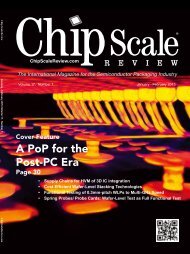
March - April’s cover represents a<br />
global view of the worldwide market for<br />
the semiconductor assembly and test<br />
services (SATS). The latest market update is<br />
presented in this issue’s editorial lineup<br />
with Integrated Circuits (<strong>IC</strong>s) Out Pacing<br />
the Economy.The top ten OSATS are evaluated<br />
in conjunction with the annual International<br />
Directory of <strong>IC</strong> <strong>Packaging</strong> <strong>Foundries</strong>.<br />
CONTENTS<br />
The International Magazine for Device and Wafer-level Test, Assembly, and <strong>Packaging</strong><br />
Addressing High-density Interconnection of Microelectronic <strong>IC</strong>'s including 3D packages, MEMS,<br />
MOEMS, RF/Wireless, Optoelectronic and Other Wafer-fabricated Devices for the 21st Century.<br />
FEATURE ART<strong>IC</strong>LES<br />
Through Silicon Vias in MEMS Product Development<br />
Carolyn White & Alissa Fitzgerald, AMFitzgerald & Associates<br />
<strong>Technology</strong> Solutions for a Dynamic and Diverse <strong>WLCSP</strong> <strong>Market</strong><br />
Ravi Chilukuri, Amkor <strong>Technology</strong><br />
Co-design Optimizes System Interconnect Paths from AS<strong>IC</strong> to<br />
Package to Board<br />
Real Pomerleau, Cisco Systems, Inc.<br />
Carlos Moll, Cadence Design Systems<br />
A Reliable Low Cost Assembly <strong>Technology</strong> for QFN Packages<br />
WL Law, Nicole Yong, SH Liew, Daniel Phuah, KF Chung and PN Ng,<br />
Carsem (M) Sdn. Bhd<br />
820A Kifer Road, Sunnyvale, CA 94086 (408) 743-9700 x331<br />
www.hcdcorp.com sales@hcdcorp.com<br />
SuperButton® SuperSpring®<br />
Featuring HCD Patented SuperButton® and SuperSpring® ® Contact<br />
Elements incorporated into socket and interposer solutions ns for<br />
prototyping, validation, space transformer, and test applications. cations.<br />
If you missed us at BiTS, be<br />
sure to stop by and see us at<br />
our next show!<br />
Bo B ar arddd-to<br />
to-Board rd<br />
Pa Pack ckag ag agee to t -B -Boa Board<br />
rd<br />
Bo Boar ardd to-F -F -Fle le l x<br />
Electronic Components &<br />
<strong>Technology</strong> Conference<br />
June 1-2<br />
Lake Buena Vista, FL<br />
Our Proprietary <strong>Technology</strong><br />
Your Competitive Advantage<br />
Copyright © 2011 High Connection Density, Inc. All rights reserved. Information is subject to change without notice. “SuperSpring” and “SuperButton” are trademarks of High Connection Density, Inc.<br />
12<br />
16<br />
20<br />
24<br />
Chip Scale Review March/April 2011 [ChipScaleReview.com] 1
2<br />
Chip Scale Review March/April 2011 [ChipScaleReview.com]
Chip Scale Review March/April 2011 [ChipScaleReview.com] 3
4<br />
Chip Scale Review March/April 2011 [ChipScaleReview.com]
FEATURE ART<strong>IC</strong>LES<br />
Die Bonding in a Mobile World<br />
Steven J. Adamson, James Klocke, Gareth DeSanctis, Alemu Dejene, Nordson Asymtek<br />
Integrated Circuits (<strong>IC</strong>s) Out Pacing the Economy<br />
Sandra Winkler, New Venture Research<br />
DEPARTMENTS<br />
From the Publisher Mother Nature Devastates a Country and Impacts an Industry<br />
Kim Newman, Chip Scale Review<br />
CONTENTS<br />
Inside Patents Patent Reform Legislation: A Reality in 2011?<br />
Contributing Legal Editors, Jason Mirabito and Carol Peters, Mintz, Levin, Cohn, Ferris, Glovsky and Popeo PC<br />
Industry News<br />
Chip Scale Review Staff<br />
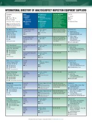
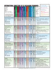
2011 International Directory of <strong>IC</strong> <strong>Packaging</strong> <strong>Foundries</strong><br />
Ron Molnar, Az Tech Direct LLC<br />
Interview PTI Eye on the Prize<br />
Chip Scale Review Staff<br />
What’s New!<br />
Advertiser Index, Advertising Sales<br />
28<br />
31<br />
Chip Scale Review March/April 2011 [ChipScaleReview.com] 5<br />
6<br />
8<br />
10,45<br />
33<br />
42<br />
46<br />
48
STAFF<br />
Kim Newman Publisher<br />
knewman@chipscalereview.com<br />
Ron Edgar Technical Editor<br />
redgar@chipscalereview.com<br />
Françoise von Trapp Contributing Editor<br />
francoise@3dincites.com<br />
Sandra Winkler Contributing Editor<br />
slwinkler@newventureresearch.com<br />
Dr. Tom Di Stefano Contributing Editor<br />
tom@centipedesystems.com<br />
Paul M. Sakamoto Contributing Editor Test<br />
paul.sakamoto@dftmicrosystems.com<br />
Jason Mirabito Contributing Legal Editor<br />
mirabito@mintz.com<br />
Carol Peters Contributing Legal Editor<br />
cpeters@mintz.com<br />
SUBSCRIPTION--INQUIRIES<br />
Chip Scale Review<br />
T 408-429-8585<br />
F 408-429-8605<br />
subs@chipscalereview.com<br />
Advertising Production Inquiries:<br />
Kim Newman<br />
knewman@chipscalereview.com<br />
EDITORIAL ADVISORS<br />
Dr. Thomas Di Stefano Centipede Systems<br />
Ron Molnar Az Tech Direct, LLC.<br />
Dr. Andy Mackie Indium Corp. of America<br />
Dr. Thorsten Teutsch Pac Tech USA<br />
Charles Harper <strong>Technology</strong> Seminars<br />
Dr. Guna Selvaduray San Jose State University<br />
Prof. C.P. Wong Georgia Tech<br />
Dr. Ephraim Suhir ERS Company<br />
Nick Leonardi Premier Semiconductor Services<br />
Copyright © 2011 by Gene Selven & Associates Inc.<br />
Chip Scale Review (ISSN 1526-1344) is a registered trademark of<br />
Gene Selven & Associates Inc. All rights reserved.<br />
Subscriptions in the U.S. are available without charge to qualified<br />
individuals in the electronics industry. Subscriptions outside of the<br />
U.S. (6 issues) by airmail are $85 per year to Canada or $95 per<br />
year to other countries. In the U.S. subscriptions by first class mail<br />
are $75 per year.<br />
Chip Scale Review, (ISSN 1526-1344), is published six times a<br />
year with issues in January-February, March-April, May-June, July-<br />
August, September-October and November-December. Periodical<br />
postage paid at Los Angeles, Calif., and additional offices.<br />
6<br />
VOLUME 15, NUMBER 2<br />
The International Magazine for Device and Wafer-level<br />
Test, Assembly, and <strong>Packaging</strong> Addressing<br />
High-density Interconnection of Microelectronic <strong>IC</strong>'s<br />
including 3D packages, MEMS, MOEMS, RF/<br />
Wireless, Optoelectronic and Other Waferfabricated<br />
Devices for the 21st Century.<br />
POSTMASTER: Send address changes to Chip Scale Review<br />
magazine, P.O. Box 9522, San Jose, CA 95157-0522<br />
Printed in the United States<br />
Chip Scale Review March/April 2011 [ChipScaleReview.com]<br />
FROM THE PUBLISHER<br />
Kim Newman<br />
Publisher<br />
Mother Nature Devastates a<br />
Country and Impacts an Industry<br />
On behalf of the entire Chip Scale Review team, I’d like to send our<br />
thoughts and prayers to all of those whose lives have been affected<br />
by the earthquake and tsunami in Japan.<br />
For the second time in a year, I find myself scrapping the original version of the<br />
publisher letter and rewriting it just in time to go to press. Last time was in October to<br />
celebrate the happy news of the Giants winning the World Series. Unfortunately this<br />
time it was because I went to sleep last night after returning from BITS Workshop and<br />
IMAPS Device <strong>Packaging</strong> Workshop with a pretty optimistic feeling about the packaging<br />
industry only to wake up to the devastating news of the earthquake and Tsunami in<br />
Japan. In barely the blink of an eye, the third largest economic power in the world was<br />
hurled into its greatest crisis situation, and things may never be the same.<br />
While many of our colleagues in Japan cared for their families and friends, the analysts<br />
were starting to assess the impact this natural disaster will have on the semiconductor<br />
industry. Initial concerns were a potential shortage of silicon, and memory components<br />
such as DRAM and NAND flash. A preliminary report from Jon Cassell of IHS iSuppli<br />
predicts that “the major impact on Japan’s semiconductor production is not likely to be<br />
direct damage to production facilities, but disruption to the supply chain.”<br />
Before the disaster, I had OSATS on the brain because this is our annual OSATS<br />
issue. In it you’ll find an interview with Scott Jewler, President of Powertech Technologies<br />
USA, an award-winning technical feature by Amkor, and a directory of packaging<br />
foundries with an introductory report from contributing editor, Sandra Winkler.<br />
There are a lot of them out there, so how is it that it’s always the same top four companies<br />
that trade off their positions, yet together control the majority of market share? Ask anyone<br />
in the know and they’ll rattle them off: ASE, Amkor, SPIL, and STATS ChipPAC.<br />
Last year, ASE took the lead, presumably because of its decision to invest in copper<br />
processes. Another contributing factor is that while they’re diversified, most<br />
manufacturing takes place in Taiwan and China. Amkor, on the other hand, is widely<br />
diversified, adding to operational cost. They’ve changed strategy to focus on debt<br />
reduction rather than capex spending. However, they are technology innovators and<br />
are in the forefront visually. SPIL had a good run in first position (2005, 06, 07)<br />
thanks to being a fast follower on technology, low overhead, being a megasite operation<br />
with a controlled geographical footprint and strong customer relations. Unfortunately,<br />
they seem to have lost the recipe in the last few years, dropping off 10-15%. Some<br />
attribute it to lost business to ASE and being slow to adopt copper. Currently in<br />
fourth place, STATS ChipPAC is privatized, and is therefore constrained on capex<br />
although not as excessively as Amkor. Still, I’m told that the company seems to struggle<br />
to execute at high level. I’m curious to see if this ranking gets shaken up as nextgeneration<br />
technologies come to market; both on the WLP and 3D front.
Chip Scale Review March/April 2011 [ChipScaleReview.com] 7
INSIDE PATENTS<br />
By the time you read this article,<br />
Congress will have been<br />
debating and arguing over the<br />
content of long-awaited comprehensive<br />
patent reform legislation for nearly two<br />
years. Two reasons that such legislation<br />
has not passed include partisanship<br />
(which is probably not a surprise) and the<br />
opposing positions of high-tech companies<br />
vs. pharmaceutical companies on this<br />
legislation. However, a new bill entitled<br />
The Patent Reform Act of 2011, recently<br />
approved by the Senate Judiciary<br />
Committee and on its way to the Senate,<br />
promises to be an acceptable bi-partisan<br />
bill with decent hopes of being passed.<br />
While the legislation is far- encompassing,<br />
we direct your attention to the more<br />
important provisions in the present bill.<br />
Change from “First to Invent” to<br />
“First to File” System<br />
In the United States (and only in the<br />
United States), a patent grants to the entity<br />
“first to invent” a particular invention. In<br />
almost all, if not all other countries, the entity<br />
that beats it to the door of the patent office<br />
first, or, in other words the entity “first to<br />
file” a patent application, is considered<br />
to be the first inventor. The proposed Patent<br />
Reform Act will harmonize U.S. patent<br />
law to that of other countries and will<br />
switch the U.S. patenting system from a<br />
“first to invent” to a “first to file” system.<br />
This change has been a relatively<br />
controversial subject, and small companies<br />
and others have alleged that larger companies<br />
have better ability (more money, engineers,<br />
and infrastructure) to file their patent<br />
applications first. However, adoption of<br />
the “first to file” system will eliminate the<br />
very complex and expensive interference<br />
8<br />
Chip Scale Review March/April 2011 [ChipScaleReview.com]<br />
Patent Reform Legislation:<br />
A Reality in 2011?<br />
By Contributing Legal Editors, Jason Mirabito and Carol Peters [Mintz, Levin, Cohn,<br />
Ferris, Glovsky and Popeo PC]<br />
procedure available within the U.S.<br />
Patent Office to determine inventorship.<br />
Third Party Review of Patent Office<br />
Decisions<br />
Under present U.S. patent law, once the<br />
Patent Office issues a patent, the public has<br />
the ability to file a request for reexamination<br />
of the granted patent. The reexam<br />
request is based on and limited to<br />
printed “prior art,” including patents and<br />
publications that a re-exam requester alleges<br />
invalidates one or more claims of the patent.<br />
Also, depending on the vintage of the patent,<br />
the requestor’s participation in the re-exam<br />
process may be permitted under present law.<br />
Under the proposed new legislation,<br />
the rights of third parties will be further<br />
expanded and a third party post-grant review<br />
process will be available. This is primarily<br />
based on the belief that third parties have<br />
more incentive to weed out “bad” patents.<br />
Thus, in addition to the current reexamination<br />
procedures, third parties will be permitted<br />
to request review of the granted patent<br />
through the post-grant review process. It<br />
is expected that the post-grant review will<br />
be broader than the present scope of reexamination<br />
procedures, which are limited<br />
to prior art patents and publications. In<br />
addition, the legislation would allow third<br />
parties to send prior art to the Patent Office<br />
during the pendency of a patent application<br />
prior to its issuance as a patent. Presumably,<br />
third parties will have become aware of a<br />
competitor’s potential patent once the<br />
Patent Office has published the corresponding<br />
application. The main purpose of adding<br />
greater third party participation in both the<br />
pre-grant and post-grant era is to ensure that<br />
weak patents are eliminated. The proposed<br />
legislation is in response to third party<br />
criticism, whether deserved or not, alleging<br />
that the Patent Office is not “doing its job.”<br />
False Patent Marking<br />
In an earlier column, we discussed the<br />
relatively recent spate of false marking suits<br />
that have been brought under the false marking<br />
provision of the patent statute. These cases<br />
allege that certain products have been marked<br />
with patent numbers representing patents<br />
that are either expired or do not cover the<br />
product. Penalties are available under the false<br />
marking provision, and any penalty that a<br />
court grants or that parties settle upon is split<br />
between the plaintiff and the U.S. government.<br />
Presently, anyone may bring a false<br />
marking action. The proposed legislation<br />
would not remove the false marking<br />
provision from the statute, but, rather,<br />
would require that the entity bringing the<br />
action demonstrate that it has actually<br />
been harmed by the alleged false marking.<br />
Controversial Provisions<br />
One of the reasons patent reform legislation<br />
has bounced around Congress for so long is<br />
due to the presence of a number of industrydividing<br />
provisions. Earlier versions of the<br />
legislation would have imposed limitations<br />
on damages for patent infringement. Industries<br />
are divided on this issue. High-tech companies<br />
were in favor of the proposed limitations,<br />
while pharmaceutical companies were against<br />
such limitations. Rather than let these provisions<br />
torpedo the remainder of the legislation,<br />
the Congress has removed them from the<br />
current bill. These changes should increase the<br />
chances of the new legislation becoming law<br />
in the current Congress and, if passed, such<br />
legislation will probably be the most<br />
comprehensive reform of U.S. patent law since<br />
the 1952 Patent Act, almost 60 years ago.
Chip Scale Review March/April 2011 [ChipScaleReview.com] 9
INDUSTRY NEWS<br />
Announcing IWLPC Platinum Sponsors<br />
As plans for IWLPC’s 2011 technology<br />
program are well underway, Chip Scale<br />
Review magazine<br />
and SMTA are<br />
pleased to announce<br />
this year’s Platinum<br />
Sponsors, Amkor<br />
Technologies and<br />
EV Group.<br />
Amkor <strong>Technology</strong>, Inc. is one of the<br />
world’s largest providers of advanced<br />
semiconductor assembly and test<br />
services.<br />
Founded<br />
in 1968,<br />
Amkor has<br />
become a strategic manufacturing partner<br />
for many of the world’s leading semiconductor<br />
companies and electronics OEMs, providing<br />
a broad array of advanced package design,<br />
assembly and test solutions. Amkor’s<br />
operational base encompasses more than<br />
5 million square feet of manufacturing<br />
facilities, product development centers,<br />
and sales & support offices in Asia, Europe<br />
and the United States. Amkor offers a suite<br />
of services, including electroplated wafer<br />
bumping, probe, assembly and final test.<br />
Amkor is a leader in advanced copper pillar<br />
bump and packaging technologies which<br />
enables next generation flip chip interconnect.<br />
EV Group (EVG) is a world leader in<br />
wafer-processing solutions for semiconductor,<br />
MEMS and nanotechnology applications.<br />
Through its flexible manufacturing model,<br />
EVG develops reliable, high-quality, lowcost-of-ownership<br />
systems that are easily<br />
integrated into customers’ fab lines. Key<br />
products include<br />
wafer bonding,<br />
lithography/<br />
nanoimprint<br />
lithography<br />
(NIL), metrology, photoresist coating,<br />
cleaning and inspection equipment.<br />
Founded in 1980, EVG is headquartered<br />
in St. Florian, Austria, and operates via<br />
a global customer support network,<br />
with subsidiaries in Tempe, AZ.;<br />
Albany, NY; Yokohama and Fukuoka,<br />
Japan; Seoul, Korea and Chung-Li,<br />
Taiwan. [www.EVGroup.com]<br />
10<br />
Chip Scale Review March/April 2011 [ChipScaleReview.com]<br />
Press lunch panelists, left to right, Dirk Hilbert, Alain Astier,<br />
Heinz Kundert, André-Jacques Auberton-Hervé, Jens Drews<br />
SEMI ISS Europe: Capitalizing on<br />
European Strengths in the Supply Chain<br />
The SEMI Industry Strategy Symposium<br />
(ISS) focuses both on strategy and<br />
technology, exploring how to best<br />
position the unique added value of<br />
Europe’s semiconductor industry on the<br />
global market. Held at different locations<br />
each year, the 2011 event took place in<br />
Grenoble, France from Feb 27-March 1.<br />
During the press luncheon, European<br />
industry executives offered their<br />
perspectives. Here are some highlights:<br />
● Heinz Kundert, President, SEMI<br />
Europe and moderator of the press<br />
conference, reported that that SEMI<br />
has made progress in getting the<br />
European Commission and EU States<br />
to recognize the semiconductor<br />
industry as strategic for Europe, and<br />
make it a priority to maintain<br />
Europe’s competitiveness.<br />
● Alain Astier, Group Vice President,<br />
Industrial Strategy, STMicroelectronics<br />
and member of the SEMI Europe<br />
Advisory Board talked about<br />
Europe’s strengths, most notably the<br />
ability to work together in partnership<br />
across the value chain.<br />
● Jens Drews, Director Government<br />
Relations, Global<strong>Foundries</strong> talked<br />
about the company’s investment in<br />
Dresden, where they are hiring 80 new<br />
employees a month. He said this is<br />
proof that Europe can be competitive<br />
in the microelectronics industry.<br />
● André-Jacques Auberton-Hervé,<br />
President and CEO, SOITEC, and<br />
chairman of the SEMI Europe<br />
Advisory board addressed the need<br />
to support those European businesses<br />
capable of creating and massproducing<br />
new products in order to<br />
create a virtuous circle of growth in<br />
their ecosystems. Three competitiveness<br />
pillars for Europe include applied<br />
research to set up the required<br />
technology platforms, industry<br />
consortiums to build pilot demonstrator<br />
production lines, and competitive,<br />
solidly-anchored local businesses<br />
with mass production capabilities.<br />
● Dirk Hilbert, Deputy Mayor,<br />
Dresden, Germany gave some interesting<br />
statistics about how Germany’s public<br />
investment in the industry has achieved<br />
returns in excess of 100%, and means<br />
that the tax revenues generated actually<br />
outstripped the initial investments.<br />
Henkel and Hitachi Chemical Sign<br />
License Agreement for Die Attach Film<br />
Henkel Corporation announced it has<br />
entered into a license agreement with Hitachi<br />
Chemical Co., Ltd. for the worldwide<br />
manufacture and sales of certain dicing<br />
die attach film. In this agreement, Hitachi<br />
Chemical has granted Henkel a worldwide<br />
license under the technology described in<br />
Hitachi Chemical’s Taiwanese Patent No.<br />
303454, and all related counterpart patents<br />
to manufacture and sell dicing die attach film.<br />
Leti Develops C2W Direct Metallic<br />
Bonding <strong>Technology</strong><br />
CEA-Leti has established a multipartner<br />
project to demonstrate highalignment-accuracy<br />
(
the chip and the substrate electrically<br />
through local metallic bonding.<br />
To demonstrate the technology, Leti<br />
acquired a customized 300mm FC300 pickand-place<br />
tool from Smart Equipment<br />
<strong>Technology</strong> (SET). The equipment was<br />
developed by SET based on its high<br />
placement accuracy FC300 system to<br />
adapt it to direct-metallic-bonding<br />
requirements. It will be used by the<br />
Minalogic PROCEED project, a •4.2M<br />
24-month project supported by French<br />
Fond Interministeriel Unique (FIU).<br />
Partners also include STMicroelectronics,<br />
ALES and the CNRS-CEMES.<br />
“This collaboration puts Leti in a very<br />
good worldwide position for 3Dtechnologies<br />
development,” said Leti<br />
CEO Laurent Malier. “We will identify the<br />
key challenges of 3D product engineering,<br />
and C2W strategy with direct-metallic<br />
bonding is a very promising option for<br />
overcoming those challenges.”<br />
Alchimer’s Wet Deposition Products<br />
Licensed for MEMS 3D Research<br />
To support its metallization processes<br />
for 3D MEMS, the Centre de Collaboration<br />
MiQro Innovation/MiQro Innovation<br />
Collaborative Centre (C2MI), located in<br />
Sherbrooke, PQ, Canada, has licensed<br />
Alchimer’s suite of electrografting products.<br />
Alchimer provides nanometric deposition<br />
technology for through-silicon vias (TSVs),<br />
semiconductor interconnects, MEMS and<br />
other electronic applications to the<br />
semiconductor and MEMS industries.<br />
Electrografting is Alchimer’s breakthrough<br />
electrochemical process that enables the<br />
growth of extremely high-quality polymer<br />
and metal thin films.<br />
The C2MI, which includes a state-ofthe-art<br />
MEMS facility, was launched in 2009<br />
by Université of Sherbrooke in Bromont<br />
Technoparc, Quebec,Canada. The center’s<br />
200mm MEMS and 3D wafer-levelprocessing<br />
(WLP) equipment will enable<br />
its members to test a variety of materials<br />
for MEMS production.<br />
“Alchimer’s Electrografting technology<br />
dramatically increases yields in MEMS,<br />
3D-<strong>IC</strong> and on-chip interconnects, and<br />
provides strong support for work in<br />
advancing the technology for 3D MEMS<br />
manufacturing with a cost-effective<br />
approach,” said Luc Ouellet, vice-president<br />
of R&D at pure-play MEMS foundry,<br />
Teledyne DALSA Semiconductor.<br />
“The MiQro Innovation Collaborative<br />
Centre and its members are at the leading<br />
edge of 3D integration in MEMS,” said<br />
Alchimer CEO Steve Lerner. “They are<br />
pushing the design rules in this space, and<br />
we are excited that they have chosen our<br />
products to support this work. This is another<br />
solid technical validation for Alchimer’s<br />
products and wet deposition technology.”<br />
<strong>Worldwide</strong> <strong>IC</strong> <strong>Packaging</strong> <strong>Market</strong>,<br />
2011 Edition, to be Released in May<br />
The semiconductor industry has been<br />
cyclical since its inception, but the general<br />
trend for the industry is upwards. The<br />
downturn of 2009 reversed itself by the<br />
second half of the year, catapulting 2010<br />
into a year of tremendous growth.<br />
A soon to be released report, The <strong>Worldwide</strong><br />
<strong>IC</strong> <strong>Packaging</strong> <strong>Market</strong>, 2011 Edition, offers<br />
an in-depth look at the worldwide integrated<br />
circuit (<strong>IC</strong>) packaging market. The forecasts<br />
of individual <strong>IC</strong> device markets are provided,<br />
for units, revenue, and ASP, from 2008<br />
through 2014, with package solutions for<br />
each of these markets broken down into I/O<br />
ranges. Additionally, package types are rolled<br />
up to deliver an overall worldwide forecast<br />
of <strong>IC</strong> packages, divided into 12 different<br />
package families, plus bare die solutions.<br />
The contract <strong>IC</strong> packaging market is<br />
forecast and supplied in a separate chapter.<br />
Units and revenue are analyzed by package<br />
family. Forecasts are computed by compiling<br />
information obtained from each individual<br />
contract assembly company. Pricing<br />
information is provided by I/O count and<br />
price per I/O, and when multiplied by units,<br />
yields revenue. Profiles of individual contract<br />
<strong>IC</strong> package assemblers are also provided,<br />
as is a chapter on the state of the industry.<br />
The <strong>IC</strong> packaging market is evolving to<br />
keep pace with other changing markets.<br />
Through extensive primary and secondary<br />
research, this report presents an objective<br />
look at the world of <strong>IC</strong> packaging.<br />
[www.newventureresearch.com]<br />
(continued on Page 45<br />
Chip Scale Review March/April 2011 [ChipScaleReview.com] 11
Through Silicon Vias in MEMS Product Development<br />
By Carolyn White and Alissa Fitzgerald [AMFitzgerald & Associates]<br />
The demand for smaller, faster,<br />
and more powerful integrated<br />
circuits (<strong>IC</strong>s) has fueled<br />
aggressive development in the areas of<br />
materials, thin film deposition, lithography,<br />
etching, and packaging. While many of<br />
the fundamental designs were introduced<br />
decades ago, microelectromechanical<br />
systems (MEMS) and the concept of<br />
silicon as a mechanical material as a field<br />
did not mature into its own until the<br />
fabrication methods developed for <strong>IC</strong>s<br />
1, 2<br />
provided a platform for development.<br />
As it has developed, MEMS technology<br />
has tapped into the analog roots of <strong>IC</strong>s as<br />
well as pushed the boundaries of how we<br />
interact with the physical world. Along<br />
the way, MEMS engineers developed<br />
methods for deep silicon etching, thick<br />
film deposition, and wafer bonding.<br />
Many of these MEMS-specific processes<br />
are now finding their way back into <strong>IC</strong>s<br />
in the form of through silicon vias (TSVs)<br />
and wafer level package (WLP).<br />
The advantages of TSV are well<br />
documented and include decreasing die<br />
size, allowing denser interconnect<br />
layouts, providing more reliable electrical<br />
connections, and hermetic cavity<br />
electrical feedthrough. 3, 4, 5, 6 Their benefits<br />
in WLP are especially attractive to MEMS<br />
and <strong>IC</strong> designers and manufacturers:<br />
simplified dicing, no wire bonding, and<br />
surface mounting without additional<br />
packaging.<br />
In the <strong>IC</strong> world, TSV technology is<br />
providing a path beyond that defined by<br />
Moore’s Law. 4 It is enabling heterogeneous<br />
integration of memory, RF, logic, etc. and<br />
providing shorter, better insulated<br />
interconnects, which leads to increased<br />
data transfer speeds, decreased parasitic<br />
5, 6<br />
capacitance and increased bandwidth.<br />
TSV can also improve integration of<br />
MEMS devices with AS<strong>IC</strong> chips. At one<br />
point, the holy grail in MEMS product<br />
development was a one-chip MEMS+AS<strong>IC</strong><br />
solution. That approach proved to be cost<br />
prohibitive because of the discrepancy<br />
between the production yield of <strong>IC</strong>s<br />
12<br />
(>99%) and MEMS (>80%, if<br />
you are lucky!) and has mostly<br />
been abandoned in favor of a<br />
two-chip module. The need for<br />
smaller packaging (originally<br />
the motivator for the one chip<br />
solution) remains, especially for<br />
applications related to consumer<br />
electronics. TSV now presents<br />
an elegant solution to this<br />
problem.<br />
Chip Scale Review March/April 2011 [ChipScaleReview.com]<br />
TSV Type<br />
Conductor<br />
Insulator<br />
Form factor<br />
Process order<br />
Advantages<br />
Disadvantages<br />
Types of TSV<br />
There are many types of TSVs, but the<br />
overall components are the same: a<br />
conductive path through the wafer that is<br />
isolated from the rest of the substrate. The<br />
conductive path is usually supplied by<br />
metal (tungsten or copper) or doped<br />
silicon. The insulator ranges from oxide<br />
to proprietary films developed by TSV<br />
suppliers or individual manufacturers<br />
(Table 1).<br />
Most TSV processing falls into two<br />
major categories, via first or via last, which<br />
refers to whether the via is done before or<br />
7, 8, 9<br />
after device process steps, respectively.<br />
The CMOS compatibility of a process,<br />
the via fill factor and aspect ratio, wafer<br />
thinning, and thermal budget usually play<br />
a role in determining which TSV process<br />
is best for a particular device design.<br />
The challenges of implementing TSV<br />
are real and can be daunting. Forming the<br />
via, or hole, is often the easiest part of<br />
the processing. Providing a reliable<br />
dielectric and/or conductive material fill<br />
_ free of voids and with structural<br />
integrity _ is the tricky part and can<br />
require significant development. Vias<br />
may be fully plugged with metal, or just<br />
sidewall coated; either way, subsequent<br />
thermal exposure during processing can<br />
cause metal to expand and contract,<br />
inducing strain in the substrate and<br />
sometimes resulting in failure of the TSV<br />
or the wafer. 7, 10 Thermal cycling can also<br />
affect the planarity of the metal fill and<br />
even the wafer, in turn affecting<br />
subsequent processing and/or wafer<br />
Metal<br />
Silicon<br />
Tungsten or copper<br />
Silicon oxide, silicon<br />
nitride, other dielectrics<br />
and proprietary materials<br />
Deposited plug or<br />
sidewall coating<br />
Via first or last<br />
Lower resistance,<br />
higher density<br />
Lower aspect ratio, requires<br />
diffusion barrier layer<br />
Highly-doped silicon<br />
Silicon oxide,<br />
proprietary materials<br />
Formed from<br />
substrate material<br />
Via first<br />
Higher aspect ratio<br />
Higher resistance,<br />
lower density<br />
Table 1. Summary of Metal vs. Silicon TSV Properties.<br />
bonding. Wafer thinning to reveal the<br />
TSV can also result in significant wafer<br />
warping or cracking.<br />
Silicon vias use the substrate material<br />
as the conductive path, which needs to<br />
be isolated from the rest of the substrate<br />
and neighboring vias using a trench etch.<br />
The aspect ratio of the trenches around<br />
these types of vias is often quite large,<br />
and providing a conformal, mechanically<br />
sound dielectric fill requires considerable<br />
development and often pushes the limit<br />
of existing fabrication tools.<br />
Progress has been made in finding<br />
solutions to these technical challenges<br />
with considerable development. Companies<br />
that have successfully developed TSV for<br />
MEMS and who provide foundry services<br />
include, but are not limited to,<br />
Austriamicrosystems, ALLVIA, IMT,<br />
IPDiA and Silex Microsystems.<br />
Advantages of TSV for MEMS<br />
In MEMS devices, TSVs can enable<br />
improvements at three levels: package,<br />
chip, and device. Some examples illustrating<br />
these improvements are described here.<br />
Package Level Improvements: TSV<br />
for Medical Devices<br />
The benefits of TSVs at the package<br />
level can be illustrated by a catheter<br />
pressure sensor, used in many medical<br />
procedures. The extreme form factor<br />
restrictions of catheters strongly affect the<br />
sensor design. Reduction in sensor size<br />
can allow for data collection where it<br />
previously was not possible, or allow the
space to be repurposed for sensor<br />
improvements (e.g. increased range/<br />
sensitivity, temperature compensation).<br />
The image on the left side of Figure 1<br />
illustrates a MEMS pressure sensor with<br />
conventional packaging components.<br />
Space on the silicon sensor must be<br />
allocated for bond pads. The bond pads<br />
are typically connected to a package substrate<br />
using wire bonds that have both vertical<br />
and horizontal space requirements and<br />
can make hermetic sealing difficult due<br />
to their surface area and fragility. The<br />
package substrate must then connect to a<br />
wire harness that relays the signal to an<br />
external data acquisition system.<br />
TSVs can provide significant space and<br />
packaging improvements for catheter<br />
applications by eliminating the need for bond<br />
pads and enabling a direct connection to<br />
a much thinner flex circuit, as shown on<br />
the right hand side of Figure 1. Smaller<br />
die and smaller catheters can immediately<br />
enable new medical applications simply<br />
by being able to move into smaller spaces.<br />
For example, a femoral artery catheter is<br />
typically 4F-10F (1.3-3.3 mm in<br />
diameter), but a 3F catheter (1 mm) or<br />
smaller can fit into a coronary artery.<br />
Chip Level Improvements: TSV in WLP<br />
The benefits of TSVs at chip level can<br />
be illustrated by a WLP example, where<br />
a top cap wafer is applied to the device<br />
wafer to create hermetic cavities. Figure<br />
2 illustrates the footprint reduction that<br />
can be achieved using TSV to bring<br />
Figure 1. Package Level Improvements.<br />
Figure 2. Chip Level Improvements.<br />
electrical signals out from a hermetic<br />
cavity. Without TSVs, electrical connections<br />
must be made using lateral routing, which<br />
requires more surface area and extra<br />
process steps of masking, deposition and<br />
planarization. With TSVs, electrical<br />
connections can be made through the<br />
backside of the wafer.<br />
In addition to saving silicon area costs,<br />
packaging costs can be reduced. In the first<br />
scenario, two wafer dicing passes must be<br />
completed, one to cut through the top wafer<br />
only and one to cut through the entire stack.<br />
This is required to have access to the<br />
electrical contact on the top surface of the<br />
bottom wafer. Once diced, standard wirebond<br />
techniques are used for interconnect,<br />
which take up package space.<br />
With the TSV, only one dicing pass is<br />
needed though the entire wafer stack. The<br />
die can now be surface mounted with<br />
technology such as solder ball joints,<br />
saving time, space and cost.<br />
Device Level Improvements: TSV for<br />
Bolometer Arrays<br />
In some cases, TSV can improve the<br />
operation of the MEMS device itself. (A<br />
few of these benefits for <strong>IC</strong>s have been<br />
outlined previously in this paper.) In the<br />
field of MEMS, imaging technology has<br />
proven to be a beneficiary of the technology.<br />
For example, Toshiba was able to achieve<br />
a 55% reduction in volume and 36% in<br />
footprint in their chip scale camera by<br />
implementing TSVs. 11<br />
One area where MEMS-based imaging<br />
technology is becoming<br />
increasingly prevalent<br />
is uncooled infrared<br />
imaging. MEMS<br />
fabrication techniques<br />
are used to produce<br />
bolometer arrays,<br />
which measure<br />
electromagnetic<br />
radiation by sensing<br />
small changes in<br />
temperature, usually<br />
by resistive means.<br />
MEMS bolometer<br />
development has<br />
enabled concurrent<br />
improvement of<br />
device performance<br />
and cost reduction<br />
Chip Scale Review March/April 2011 [ChipScaleReview.com] 13
ecause the 3D fabrication techniques<br />
result in suspended sensing membranes<br />
with superior thermal isolation. In<br />
addition, MEMS-based WLP in vacuum<br />
has improved the performance of MEMS<br />
bolometers because the vacuum<br />
eliminates the thermal conduction of air<br />
between the device and the surrounding<br />
package. 12<br />
Another important contributing factor<br />
to MEMS bolometers’ performance is the<br />
pixel fill. On the left hand side of Figure<br />
3, a sketch of a typical MEMS bolometer<br />
design with space dedicated to electric<br />
interconnects and routing, is illustrated.<br />
Even in the best layout and processing<br />
situations, up to 25% of the imaging area<br />
can be consumed by these connections.<br />
When this routing is replaced by TSV, the<br />
area consumed by routing can be greatly<br />
reduced, improving optical fill factor and<br />
increasing pixel density. TSV also makes<br />
it easier to use wafer level packaging to<br />
package the bolometers in a vacuum.<br />
Including TSV During MEMS<br />
Development<br />
Until recently, TSV was only available<br />
to foundry customers, in other words,<br />
MEMS devices that were already being<br />
produced in volume. Integration of TSV<br />
could therefore not be considered nor<br />
implemented until the MEMS device was<br />
fully mature. However, an all too familiar<br />
situation for companies is to find<br />
themselves, after working hard to develop<br />
their core MEMS technology, having<br />
commercialization efforts delayed by<br />
packaging challenges, many of which<br />
could be easily solved with TSV.<br />
Successful leverage of TSV benefits<br />
requires integrating and testing the<br />
technology early in the MEMS development<br />
cycle, not tacking it on later as an<br />
afterthought. TSV should be considered<br />
early in the overall MEMS design, since<br />
it may simplify MEMS design or possibly<br />
14<br />
Figure 3. Device Level Improvements.<br />
Chip Scale Review March/April 2011 [ChipScaleReview.com]<br />
create process issues that impact MEMS<br />
process flow. Likewise, the presence of<br />
TSV strongly influences package and<br />
assembly design. If a company waits until<br />
after MEMS development to consider TSV,<br />
they will likely discover that the pain,<br />
time, and cost of re-designing their MEMS<br />
device and package to accommodate TSV<br />
will more than neutralize the potential<br />
benefits of the technology.<br />
Recognizing this important need for<br />
TSV during MEMS development, a<br />
MEMS development firm* and a pure<br />
play MEMS foundry † have teamed up to<br />
enable customers to integrate and<br />
evaluate proven foundry TSV technology<br />
in prototypes. Product cost, time, and risk<br />
may be reduced by identifying and<br />
solving package and process issues early,<br />
simplifying system design and reaping the<br />
benefits of TSV integration much sooner<br />
in the product roadmap.<br />
Standardized TSV <strong>Technology</strong><br />
Figure 4. Cross-section of Sil-Via ® Substrate. (Courtesy of Silex Microsystems)<br />
Sil-Via ® , a proprietary silicon via<br />
technology provided by the MEMS<br />
foundry, has a proven history of volume<br />
production supply into a wide range of<br />
MEMS applications, including the<br />
cellular handset market. 13 It is a via-first<br />
process and therefore must be considered<br />
in the MEMS design process.<br />
The vias are formed by etching an<br />
annular trench into low resistivity silicon.<br />
The trench is then filled with a dielectric<br />
to isolate the silicon via from the substrate<br />
(Figure 4). The resulting via is mechanically<br />
stable and robust across a wide temperature<br />
range. Electrical connection to the via<br />
may be made using solder balls, gold stud<br />
bumps or similar technology (Figure 5).<br />
Sealed MEMS chips with TSVs may be<br />
directly mounted to circuit boards or flex<br />
circuits by surface mount techniques.<br />
Methodology for Prototyping<br />
Two possible options have been created<br />
for incorporating these silicon vias into<br />
MEMS prototypes. The first option uses<br />
a standard TSV pattern _ similar in layout<br />
to a breadboard _ that is available at lower<br />
cost and shorter lead time. Depending on<br />
the MEMS device design, an interconnect<br />
routing layer may be needed to integrate<br />
the device design with the TSV pattern.<br />
Such prototypes will likely have a lessthan-ideal<br />
form factor, but for early stage<br />
development that may not be important.<br />
The second option is a<br />
custom TSV pattern. This<br />
option incurs higher costs<br />
and longer lead times, but<br />
allows the TSV pattern to<br />
be built to the customer’s<br />
specifications.<br />
Figure 6 outlines the<br />
method for incorporating<br />
TSVs during the MEMS<br />
development process. Initial<br />
device design, modeling<br />
and layout occurs with<br />
silicon via design and<br />
fabrication rules in mind.<br />
During prototype fabrication,<br />
the TSVs are created first by<br />
the MEMS foundry, and then<br />
the MEMS development<br />
firm completes the device<br />
processing. Small wafer<br />
Figure 5. Surface Electrical Routing and Solder Bumps. (Courtesy of Silex Microsystems) batches (10 wafers or more),
which are essential during early stage<br />
development, are available. When prototyping<br />
is completed, the MEMS design can be<br />
quickly ramped up to volume, having been<br />
developed on a standardized TSV process<br />
platform.<br />
Summary<br />
Many MEMS devices can benefit from<br />
the use of TSV to meet performance<br />
demands, challenging form factors or<br />
packaging requirements. Too often, TSV<br />
is not considered until late in the<br />
development process or after the product<br />
design is finished. Integrating a standardized<br />
TSV during the prototyping stage provides<br />
a strategic advantage in terms of reduced<br />
timeline, risk, and cost. In particular, evaluating<br />
packaging solutions early on allows new<br />
MEMS designs to move faster and with<br />
more confidence into volume production.<br />
For more information, please contact<br />
AMFitzgerald at tsv@amfitzgerald.com.<br />
* AMFitzgerald (Burlingame, CA USA)<br />
† Silex Microsystems (Järfälla, Sweden)<br />
Sil-Via ® is a trademarked and patented<br />
process developed by Silex Microsystems<br />
References<br />
1. Wise, K. D. “Integrated sensors,<br />
MEMS, and microsystems: Reflections on<br />
a fantastic voyage.” Sensors and Actuators<br />
A, Volume: 136, pp 39 - 50. 2007.<br />
2. Petersen, K.E. “Silicon as a mechanical<br />
material.” Proceedings of the IEEE,<br />
Volume: 70 Issue:5, pp 420 - 457. May 1982.<br />
3. Knickerbocker, J.U., Andry, P.S., Dang,<br />
B., Horton, R.R., Patel, C.S., Polastre, R.J.,<br />
Sakuma, K., Sprogis, E.S., Tsang, C.K.,<br />
Webb, B.C., Wright, S.L. “3D silicon<br />
integration”. 58th Electronic Components<br />
and <strong>Technology</strong> Conference. pp 538 - 543. 2008.<br />
4. Yu, C.H. “The 3rd dimension-More Life<br />
for Moore’s Law.” Microsystems,<br />
<strong>Packaging</strong>, Assembly Conference Taiwan.<br />
pp 1 - 6. 2006.<br />
5. Motoyoshi, M. “Through-Silicon Via<br />
(TSV).” Proceedings of the IEEE.<br />
Volume: 97 Issue:, pp 43 - 48. 2009.<br />
Figure 6. TSV Prototype Development Method.<br />
6. Burns, J., McIlrath, L., Keast, C., Lewis,<br />
C., Loomis, A., Warner, K., and Wyatt, P.<br />
“Three-dimensional integrated circuits<br />
for low-power, high-bandwidth systems<br />
on a chip.” 2001 IEEE International Solid-<br />
State Circuits Conference. pp 268 - 269,<br />
453. 2001.<br />
7. Ramm, P., Wolf, M.J., Klumpp, A.,<br />
Wieland, R., Wunderle, B., Michel, B.,<br />
Reichl, H. “Through silicon via technology<br />
- processes and reliability for wafer-level<br />
3D system integration.” 58th Electronic<br />
Components and <strong>Technology</strong> Conference.<br />
pp 841 - 846. 2008<br />
8. Beica, R., Sharbono, C., Ritzdorf, T.<br />
“Through silicon via copper electrodeposition<br />
for 3D integration.” 58th Electronic<br />
Components and <strong>Technology</strong> Conference,<br />
pp 577 - 583. 2008<br />
9. Puech, M., Thevenoud , J.M., Gruffat,<br />
J. M., Launay, N., Arnal, N., Godinat, P.<br />
“DRIE achievements for TSV covering<br />
Via First and Via Last Strategies.”<br />
www.alcatelmicromachining.com/<br />
amms_en/download/docs/news/<br />
doc214.pdf<br />
10. Selvanayagam, C.S., Lau, J.H.,<br />
Xiaowu Zhang, Seah, S., Vaidyanathan,<br />
K., Chai, T.C. “Nonlinear Thermal Stress/<br />
Strain Analyses of Copper Filled TSV<br />
(Through Silicon Via) and Their Flip-<br />
Chip Microbumps.” IEEE Transactions<br />
on Advanced <strong>Packaging</strong>, Volume: 32<br />
Issue:4., pp 720 - 728. 2009.<br />
11. Yoshikawa, H., Kawasaki, A.,<br />
Tomoaki, Iiduka, Nishimura, Y., Tanida,<br />
K., Akiyama, K., Sekiguchi, M., Matsuo,<br />
M., Fukuchi, S., Takahashi, K. “Chip<br />
Scale Camera Module (CSCM) using<br />
Through-Silicon-Via (TSV).” 2009<br />
Solid-State Circuits Conference - Digest<br />
of Technical Papers. pp476 - 477. 2009.<br />
12. Niklaus, F., Vieider, C., Jakobsen, H.<br />
“MEMS-Based Uncooled Infrared<br />
Bolometer Arrays - A Review.” MEMS/<br />
MOEMS Technologies and Applications<br />
III, Proc. of SPIE Vol. 6836. 2007.<br />
13. Bauer, T. “First High Volume Via Process<br />
for <strong>Packaging</strong> and Integration of MEMS /<br />
CMOS.” www.silexmicrosystems.com/<br />
<strong>Technology</strong>.asp<br />
Chip Scale Review March/April 2011 [ChipScaleReview.com] 15
<strong>Technology</strong> Solutions for a Dynamic and Diverse<br />
<strong>WLCSP</strong> <strong>Market</strong><br />
By Ravi Chilukuri, [Amkor <strong>Technology</strong>]<br />
The advent of wafer level chip<br />
scale packaging (<strong>WLCSP</strong>) in<br />
the semiconductor industry<br />
was driven by a strong push for costreduction<br />
and miniaturization. The<br />
primary utilizers of this technology have<br />
been handheld or portable products, such<br />
as cell-phones, ipods, laptops, and<br />
netbooks. However, more recently,<br />
<strong>WLCSP</strong>s are gaining foothold in other<br />
industries, such as servers and automotive<br />
electronics. Initially, reliability performance<br />
limited the use of <strong>WLCSP</strong> to smaller die<br />
sizes (
ealized through a two-mask approach, where the first polymer<br />
layer is left out of the device stack-up. Early data demonstrated<br />
that the board level reliability (BLR) performance of the above<br />
three technologies is comparable and meet the generally<br />
accepted guidelines for reliability performance. 2 the 3-mask<br />
CSP has since been tested for package level reliability using<br />
PBO, in addition to Polyimide (PI). Extensive BLR studies<br />
have also been done comparing PBO to PI. Solder alloy<br />
comparisons have been done using BLR on both the threeand<br />
two-mask CSP.<br />
Package-Level Reliability<br />
A number of package-level reliability tests were performed on<br />
parts built using the 3-mask structure with PI for both the first<br />
and second polymer level (Table 1). The die design used was a<br />
Table. Package level reliability tests performed on Polyimide and PBO based 3mask<br />
CSP structures<br />
5.5mm x 5.5mm x 0.28mm die with a 10 x 10 full bump array at<br />
0.5mm pitch.<br />
All the parts were preconditioned at MSL1 requirements. Parts<br />
were electrically and optically tested prior to preconditioning,<br />
after preconditioning, and after reliability testing. Bump shears<br />
were also performed following the reliability tests. The same<br />
process and tests were repeated on parts built using PBO for both<br />
the first and second polymer levels.<br />
PI vs. PBO BLR Comparison on 3-mask CSP<br />
In addition to the package-level reliability, board level reliability<br />
(BLR) was also evaluated for PI-based 3-mask CSP vs. PBObased<br />
3-mask CSP. The die design used for the BLR tests was a<br />
5.3mm x 5.3mm die with a 12 x 12 full bump array at 0.4mm<br />
pitch. The solder alloy used was SAC405. JEDEC drop test and<br />
thermal cycling were evaluated. The drop test board was an 8layer<br />
board, and the thermal cycle board had 4 layers. The boards<br />
used were NSMD with 250μm diameter Cu pads.<br />
The JEDEC thermal cycling condition used for this study was<br />
JEDEC JESD22-A104C, Condition G.3 Parts were cycled<br />
between -40 to 125C at 1 cycle/hour. The temperature ramp was<br />
18min. and the dwell time at temperature was 12min. Three boards<br />
with 15 mounted <strong>WLCSP</strong> devices were used for each test case.<br />
The comparison of PI- based 3-mask CSP versus PBO-based 3mask<br />
CSP shows > 2X improvement in the mean life with the use<br />
of PBO (Figure 2). With the PBO, mean life was greater than<br />
1000 cycles for this 144 I/O die with first fails of greater than 600<br />
cycles. The failure modes for both the PI and PBO versions were<br />
noted to be in bulk solder.<br />
Chip Scale Review March/April 2011 [ChipScaleReview.com] 17
18<br />
Figure 2. Temperature cycling performance<br />
comparing PI and PBO versions of 3-mask CSP<br />
Figure 4. Temperature cycling performance<br />
comparing solder alloys on PI based3-mask CSP<br />
Figure 6. Temperature cycling performance<br />
comparing solder alloys on PI 2-mask CSP<br />
The setup of the board level drop tester<br />
follows the guidelines of JEDEC drop test<br />
standards, with 15 <strong>WLCSP</strong> devices (3 x<br />
5 matrix) assembled on a test board (132<br />
x 77mm). 4-6 The testing described in this<br />
paper applied the aggressive JEDEC<br />
condition H (2900G/0.3ms). The widely<br />
used JEDEC condition B (1500G/0.5ms)<br />
proved to be impractical for these parts<br />
due to the extensive testing time required<br />
to collect sufficient data for statistical<br />
analysis. Four boards per test case were<br />
utilized for drop testing.<br />
Previously, the drop performance of the<br />
3-mask CSP for both JEDEC drop<br />
condition H (2900G/0.3ms) and condition<br />
B (1500G/0.5ms) was compared. 1 From<br />
failure analysis, the primary failure mode<br />
was found to be the separation through<br />
the IM at the Pb-free/Cu interface. The<br />
Chip Scale Review March/April 2011 [ChipScaleReview.com]<br />
Figure 3. JEDEC drop test performance comparing PI<br />
and PBO versions of 3-mask CSP<br />
Figure 5. JEDEC drop test performance comparing<br />
solder alloys on PI based 3-mask CSP<br />
Figure 7. JEDEC drop test performance comparing<br />
solder alloys on PI based 2-mask CSP<br />
acceleration factor between the two<br />
different drop conditions for this type of<br />
IMC failure was 3 x. A comparison of the<br />
condition H drop test for PI versus PBO<br />
shows no difference in the drop test<br />
performance (Figure 3). For both cases,<br />
the mean life was > 1000 drops at<br />
condition H indicating an expected life<br />
of >3000 drops at the industry wide<br />
typically used condition B using the<br />
above acceleration factor.<br />
Solder Alloy BLR Comparison<br />
BLR was also evaluated for multiple<br />
solder alloys for the PI-based 3-mask<br />
CSP. The solder alloys compared were<br />
SAC405, SAC105 and LF35. The die<br />
design used for the BLR tests was a<br />
5.3mm x 5.3mm die with a 12 x 12 full<br />
bump array at 0.4mm pitch. The boards<br />
used were NSMD with 250μm diameter<br />
Cu pads. The BLR test conditions used<br />
were the same as those described in the<br />
previous section.<br />
There was no significant difference in<br />
the thermal cycling mean life with<br />
different solder alloys on the 3-mask CSP<br />
(Figure 4). The plots for SAC105 and<br />
LF35 overlapped, as may be expected due<br />
to the similar silver content in these two<br />
alloys. Interestingly, the SAC405<br />
performance was equivalent to SAC105<br />
for the 3-mask CSP structure, within the<br />
limits of standard test variation. Failure<br />
modes for thermal cycle stressing were<br />
typically bulk solder failures.<br />
Likewise, the drop test performance of<br />
the different solder alloys on the 3-mask<br />
CSP was equivalent (Figure 5). Despite<br />
using the more aggressive drop test<br />
condition H, the first fails were at > 600<br />
drops. This performance far exceeds the<br />
typical industry requirements for drop<br />
tests. The primary failure mode for drop<br />
was noted to be at the copper solder intermetallic<br />
layer.<br />
Solder Alloy BLR Comparison on 2mask<br />
CSP<br />
BLR was also evaluated for multiple<br />
solder alloys for PI based 2-mask CSP.<br />
The solder alloys compared were<br />
SAC405 and SAC105. The die design<br />
used for the BLR tests was a 5.5mm x<br />
5.5mm die with a 10x10 full bump array<br />
at 0.5mm pitch. The boards used were<br />
NSMD with 235um diameter Cu pads.<br />
There was no significant difference in<br />
the thermal cycling mean life with<br />
different solder alloys on the 2-mask CSP<br />
(Figure 6). The SAC405 performance<br />
was equivalent to SAC105 for the 2-mask<br />
CSP structure as well, within the limits<br />
of standard test variation.<br />
Likewise, the drop test performance of<br />
the different solder alloys on 2-mask CSP<br />
was equivalent (Figure 7). Despite using<br />
the more aggressive drop test condition<br />
H, the first fails were at >500 drops. This<br />
performance far exceeds the typical<br />
industry requirements for drop tests.<br />
Bump Pitch/Height BLR Comparison<br />
The most common bump pitches used<br />
for <strong>WLCSP</strong> are 0.4mm and 0.5mm. The<br />
0.5mm pitch is fairly common on the
analog and power management <strong>IC</strong>s, and<br />
on devices going into lower-end phones.<br />
The 0.4mm pitch has become main stream<br />
in the last couple of years for <strong>WLCSP</strong><br />
with its growth in RF/high speed devices.<br />
For testing the impact of the different<br />
pitches on the 3-mask CSP, test vehicles<br />
were chosen with the same bump array at<br />
both 0.5mm pitch and 0.4mm pitch. The<br />
bump height for 0.5mm pitch and 0.4mm<br />
pitch devices was 250μm and 210μm,<br />
respectively. The BLR was evaluated for<br />
above test vehicles built using PI and<br />
SAC405. The 0.5mm pitch die design<br />
used was a 5.5mm x 5.5mm die with a 10<br />
x 10 full bump array. The boards used<br />
were NSMD with 235μm diameter Cu<br />
pads. The 0.4mm pitch die design used<br />
was a 4.5mm x 4.5mm die with a 10 x 10<br />
full bump array. The boards used were<br />
NSMD with 250μm diameter Cu pads.<br />
There was no significant difference in<br />
the thermal cycling performance of the<br />
two test vehicles on 3-mask CSP. Both<br />
samples exhibited first fails close to or<br />
greater than 1000 cycles, with mean life<br />
close to 2000 cycles. However, the drop<br />
test performance of the 0.4mm pitch<br />
device was better than that the 0.5mm<br />
pitch device. Despite using the more<br />
aggressive drop test condition H, the first<br />
fails were at > 400 drops for both<br />
samples. The mean life for 0.4mm pitch<br />
devices was however 2xX greater than the<br />
0.5mm pitch devices.<br />
Conclusion<br />
The BLR drop and thermal cycling data<br />
for 3-mask CSP and 2-mask CSP position<br />
these technologies as cost effective and<br />
viable <strong>WLCSP</strong> options. A comparison of<br />
PBO and PI based 3-mask CSP technologies<br />
exhibited >2 x improvement in thermal<br />
cycling life and comparable drop<br />
performance using PBO. With different<br />
solder alloys, both 3-mask CSP and 2-mask<br />
CSP exhibited equivalent TC and drop<br />
performance. The 0.4mm and 0.5mm pitch<br />
devices showed equivalent TC performance.<br />
* Amkor’s <strong>WLCSP</strong> offering, CSPnl .<br />
** Amkor’s CSPn3 and CSPn2<br />
Acknowledgements<br />
Appreciation is extended to our<br />
colleagues from the R&D group of<br />
Amkor Korea: SS Park, ES Yang, DH<br />
Moon, SW Cha, TK Hwang and WJ<br />
Kang, as well as former colleagues, Rex<br />
Anderson and Boyd Rogers, for their<br />
technical support and efforts.<br />
References<br />
1. R. Anderson, R. Chilukuri, T.Y. Tee,<br />
C.P. Koo, H.S. NG, B. Rogers, and A.<br />
Syed, “Advances in <strong>WLCSP</strong> technologies<br />
for growing market needs”, IWLPC<br />
Proc., San Jose, CA (2009).<br />
2. R. Anderson, R. Chilukuri, B. Rogers,<br />
and A. Syed, “Advances in <strong>WLCSP</strong><br />
technologies to enable cost reduction”,<br />
IMAPS Proc., Scottsdale, AZ (2010).<br />
3. JEDEC Standard JESD22-A104C,<br />
2005.<br />
4. JEDEC Standard JESD22-B111, 2003.<br />
5. JEDEC Standard JESD22-B104-B,<br />
2001.<br />
6. JEDEC Standard JESD22-B110, 2001.<br />
Chip Scale Review March/April 2011 [ChipScaleReview.com] 19
Co-design Optimizes System Interconnect Paths from<br />
AS<strong>IC</strong> to Package to Board<br />
By Real Pomerleau [Cisco Systems, Inc.] and Carlos Moll [Cadence Design Systems]<br />
H istorically, a semiconductor<br />
chip and the package and<br />
PCB that house it have all<br />
been designed independently. One design<br />
is completed and “thrown over the wall”<br />
to the next design team. Quite often, the<br />
PCB designer is challenged with the task<br />
of untangling interconnect that would<br />
have been better organized to connect to<br />
other devices on the PCB. A number of<br />
different design challenges, such as faster<br />
data transfer speeds, reduced overall<br />
product cost, and miniaturization of the<br />
final product size, have complicated the<br />
design process to the point where an overthe-wall<br />
approach is no longer a viable<br />
strategy. Chip, package, and PCB design<br />
must be a collaborative project to meet<br />
final product design goals.<br />
In the absence of such a collaborative<br />
process, the package designer often finds<br />
himself caught in the middle and sometimes<br />
becomes the scapegoat when a design<br />
requires a re-plan or a re-spin. For example,<br />
if package skew was not properly planned<br />
for in the overall interface timing, a chip<br />
with a high speed DDR3 interface may not<br />
be able to meet timing at the fastest memory<br />
speeds. However, if the package had been<br />
optimized within the context of the chip and<br />
the PCB, meeting timing requirements<br />
could have been much easier.<br />
Cisco and Cadence have spent the last<br />
couple of years developing a methodology<br />
that enables a package to be optimized within<br />
the context of the chip and PCB. This process<br />
was developed out of necessity when signal<br />
and power integrity issues were becoming<br />
almost impossible to resolve strictly as a<br />
PCB issue. Together, the companies found<br />
that with the right tools and methodology,<br />
time and expense can be reduced while<br />
design quality is increased.<br />
SI and PI problems haunt both the<br />
electrical and physical domains. When<br />
designs are “thrown over the wall,” the<br />
design is typically done by someone with<br />
20<br />
Chip Scale Review March/April 2011 [ChipScaleReview.com]<br />
little knowledge of the overall system<br />
constraints. With such a “siloed” design,<br />
the <strong>IC</strong> package designer may be forced<br />
to deal with a die design where the padring<br />
and bump array (for flip chips) or<br />
passivation openings (for wire-bonded<br />
chips) are located sub-optimally from a<br />
packaging perspective. Package-level signals<br />
may be routed underneath and straight across<br />
the die core _ potentially causing signal and<br />
power integrity problems _ and parallel<br />
bus interfaces may have different routing<br />
lengths _ causing signal skew across the bus.<br />
Signal wires may be scattered around the<br />
package footprint with little regard to return<br />
current causing more problems. Differential<br />
pairs are also sensitive to skew.<br />
Ideally, these signals should have<br />
matched physical and electrical lengths.<br />
At lower interface speeds, there’s enough<br />
timing margin to overcome such mismatches,<br />
but with GHz+ signaling rates, there is<br />
literally no margin to correct these<br />
mismatches on the PCB. Signal quality,<br />
crosstalk, and timing are all significant<br />
system-level challenges even with an<br />
optimized package. Trying to correct the<br />
effects on the board of a poorly designed<br />
<strong>IC</strong> package on GHz+ interface speeds is<br />
close to impossible.<br />
When power-delivery systems at the<br />
die, package, and board levels are designed<br />
separately by different design teams, there<br />
is no opportunity to optimize the powerdelivery<br />
network (PDN). Lack of, or<br />
improper use of package decoupling<br />
capacitors can possibly be fixed with<br />
additional PCB decoupling for slowerspeed<br />
board designs, but today’s highspeed<br />
systems require far better, more<br />
integrated PDN design to avoid severe<br />
PI problems. Separately designed PDNs<br />
at the PCB, package, and die levels can<br />
produce some unexpected results once<br />
they’re coupled together. Integrated codesign<br />
of all three PDNs is clearly the<br />
right approach.<br />
Figure 1. Un-optimized connectivity between a BGA<br />
package and a connector on a PCB<br />
Co-Design Reduces Package Costs<br />
Integrated co-design at the die, package,<br />
and board levels can also help reduce the <strong>IC</strong><br />
packaging cost. AS<strong>IC</strong> packages come in two<br />
types: ceramic and organic. Ceramic<br />
packages have a large number of layers to<br />
distribute die signals, but they cost more and<br />
are generally single-sourced. In contrast,<br />
cheaper organic substrates are typically<br />
limited to fewer signal layers, complicating<br />
the efforts to break signals out of the die.<br />
There are also practical limits to the<br />
number of PCB layers. Engineering teams<br />
often find themselves up against the<br />
maximum number of layers for a given<br />
board thickness or cost. High AS<strong>IC</strong> pin<br />
counts complicate matters because the
large number of I/O signals must escape<br />
the AS<strong>IC</strong>’s shadow on the board, which<br />
often consumes many board layers.<br />
When an overall system design is driven<br />
by components with predefined pin-outs, it<br />
is possible to end up with an interface where<br />
all the assigned signal pins are the mirror<br />
image of what is desired. Figure 1 shows<br />
the multiple “rat’s nests” that can result from<br />
such a constrained design approach.<br />
Connecting components with multiple rat’s<br />
nest interconnect problems is a nightmare<br />
for board-layout engineers. Un-routed<br />
signals that cross over each other will<br />
increase PCB layer count and consume<br />
most if not all of the available routing<br />
channels, making the routing of other<br />
interface signals all the more challenging.<br />
Microsoft Office Applications Aren’t<br />
Design Tools<br />
Several years ago, Cisco started to look<br />
at system-level interconnect design<br />
optimization. Early approaches required<br />
frequent meetings, emails, and re-purposed<br />
office applications such as Microsoft Visio,<br />
PowerPoint, and Excel to manage design<br />
data. Graphical data was communicated<br />
between teams using Visio and PowerPoint<br />
and netlist data was managed with Excel.<br />
Change requests from the <strong>IC</strong> design team<br />
were common and merging these changes<br />
into one Excel spreadsheet, which also<br />
tracked package and the PCB changes, was<br />
a manual and error-prone process. There<br />
was constant concern that something would<br />
go wrong and the only verification available<br />
was manual, line-by-line checking that<br />
verifies signals match from chip to package<br />
to board.<br />
In the past, designers used separate<br />
package and board design tools. As a<br />
result, coming up with an optimized<br />
overall solution was a struggle. Large-scale<br />
changes, such as moving a bus from a<br />
package’s North to South side, were fairly<br />
straightforward but without an integrated<br />
view of chip, package, and board, it was<br />
difficult to see problems such as a parallel<br />
bus mirrored between devices (which<br />
creates crossing rat’s nest on the PCB).<br />
These problems drove the need for an<br />
integrated board, package, and die design<br />
environment. Collaboration among chip,<br />
package, and PCB designers was clearly<br />
necessary to build a reliable and cost-<br />
effective product, and automation was<br />
also required. EDA companies were<br />
already aware of the need for each of these<br />
three design groups to communicate more<br />
effectively, and addressed the issue by<br />
developing a full co-design solution. On<br />
the physical side, the capability existed to<br />
import the chip’s I/O pad-ring definition<br />
into the package-design tools. Package<br />
and PCB designs were also optimized in<br />
one tool. However, before collaboration,<br />
these were separate steps and what was<br />
needed was a seamless flow.<br />
In-House Package Design is a<br />
Strategic Advantage<br />
During this collaboration, the advantage<br />
of bringing the package design internal<br />
Chip Scale Review March/April 2011 [ChipScaleReview.com] 21
Figure 2. Using System Connectivity Manager to author hierarchical <strong>IC</strong>-<br />
Package-PCB netlist<br />
to the end-user became clear, especially<br />
when considering the power and signal<br />
requirements for the company’s latest<br />
AS<strong>IC</strong>s. Designing the <strong>IC</strong> package and board<br />
together gives better control over the<br />
package footprint, which can save layout<br />
engineers a lot of board-routing time.<br />
Focusing on the PDN and optimizing the<br />
distribution of decoupling capacitors<br />
allows a reduction in overall capacitor count.<br />
This, in turn, reduces the overall product cost.<br />
While in-house package design makes<br />
it possible to work efficiently, it’s beneficial<br />
to also have the option of outsourcing<br />
package design to a third party. However,<br />
this is only possible through a distributed<br />
methodology where abstract information<br />
about chip, package, and PCB can be<br />
communicated bi-directionally with the<br />
third party.<br />
A pure vendor-supplied EDA flow is<br />
preferable because it is both expensive and<br />
risky to maintain in-house tools and<br />
software solutions. The latest versions of<br />
EDA tools provide netlist management*<br />
as well as a single-window view of chip,<br />
package, and PCB (see Figure 2) for<br />
implementation. Putting all three views<br />
together makes optimization and signal<br />
management much easier.<br />
One major difficulty in the past was<br />
managing netlists across entire systems and<br />
22<br />
Figure 3. The System Connectivity Manager (SCM) component<br />
connectivity pane can maintain different name spaces between PCB,<br />
package, and <strong>IC</strong> environments<br />
Chip Scale Review March/April 2011 [ChipScaleReview.com]<br />
keeping track of net names<br />
as a signal traverses various<br />
design hierarchy levels.<br />
The netlist management tool<br />
has been a great help in<br />
managing this hierarchical<br />
connectivity maze. Its<br />
ability to map net names<br />
among the PCB, package,<br />
and <strong>IC</strong> environments has<br />
proven quite convenient.<br />
It’s easier to define and<br />
maintain connectivity<br />
definitions in connectivity<br />
pane tables. Because it is<br />
only a logical tool the nets<br />
can be connected to the<br />
new AS<strong>IC</strong> knowing that<br />
they will be physically<br />
optimized later in the flow.<br />
Die footprint and bump<br />
connectivity can be brought<br />
into the netlist management<br />
tool in several<br />
ways. It was designed to take<br />
advantage of the implicit<br />
hierarchy that exists between<br />
PCB, package, and die, allowing<br />
for maintenance of three<br />
different name spaces that are<br />
displayed simultaneously (see<br />
Figure 3).<br />
The connectivity flow across<br />
the design hierarchy must be<br />
untangled before any physical<br />
implementation tasks begin and<br />
optimally untangling connectivity<br />
across multiple hierarchy levels<br />
is complicated. At this time, this<br />
tool implements some simple<br />
heuristics to help untangle pin<br />
assignments but there’s no<br />
guarantee that physical<br />
implementation of the result is<br />
possible. The capability of iterating<br />
between logical and physical tool<br />
set helps zooming in on a<br />
solution.<br />
At any point in the flow, the<br />
netlist management tool can<br />
import the current status of the<br />
PCB or package tool database to<br />
synchronize it with the logical<br />
definition. Because the BGA is<br />
being co-designed with die and<br />
PCB, pin optimizations to the<br />
BGA automatically propagate to the PCB<br />
as well. A simple ECO process propagates<br />
pin-out changes through the system if the<br />
co-designed BGA package or die<br />
changes.<br />
Co-Design Promotes Design Reuse<br />
The co-design solution further<br />
enhances the overall design productivity<br />
process by allowing design reuse of both<br />
logical and physical data. The integration<br />
of die, <strong>IC</strong> package and PCB at the logic<br />
level allows the reuse of blocks, library<br />
components, and fabric dependent signals.<br />
At the physical level, design reuse provides<br />
a mechanism to reuse <strong>IC</strong> place and route,<br />
package and PCB power, ground, and<br />
signal distribution. It may also include<br />
routing and optimal return path via<br />
reference locations for high speed signal<br />
reference.<br />
Importing parts of existing designs,<br />
such as a memory complex from Design<br />
Figure 4. Single-canvas interconnectivity view including PCB,<br />
package, and <strong>IC</strong> (before optimization)<br />
Figure 5. Single-canvas interconnectivity view including PCB,<br />
package, and <strong>IC</strong> (after optimization, no rat¡¯s nests)
A or a processor complex from Design B and several custom<br />
AS<strong>IC</strong>s from Design C into a new design is tremendously useful<br />
and significantly speeds design. The netlist management tool is<br />
an ideal place to support these types of transactions.<br />
Knowing the components on the PCB, BGA pin-out can be<br />
defined on the PCB to optimize board routability. Then, the BGA<br />
footprint can be driven into the <strong>IC</strong> package and then into the <strong>IC</strong><br />
pad-ring, which gives a very clean data path through the interconnect<br />
design. This path makes the PCB easier to route so that focus can<br />
turn to optimizing the electrical performance of high-speed interfaces<br />
such a SerDes differential pair or wide, high-speed, sourcesynchronous<br />
buses. In cases where an IP block on the die has a fixed<br />
pin-out, the pin-out can be mapped up through the package to the<br />
board and resolve any tangled nets at the PCB or package levels.<br />
The layout of the PCB, package, and <strong>IC</strong> pad ring is now viewed<br />
in a single canvas. Although this tool flow is still a work in<br />
progress, it provides a first-cut mechanism to optimize data paths<br />
through board, package, and chip (see Figures 4 and 5 for beforeand<br />
after-optimization views).<br />
Summary<br />
Automatic pin optimization permits global pin-assignment<br />
changes among PCB, package, and <strong>IC</strong>. Individual pin-swap<br />
capabilities allow quick fine-tuning of assignments (see Figure<br />
6). Once optimizations are complete the results are read back<br />
into the netlist management tool, then export individual board<br />
and package files for physical layout. <strong>IC</strong> pin definitions are written<br />
from the single-canvas view and then imported directly into an<br />
implementation system for the <strong>IC</strong> design.** This design flow<br />
preserves net names for each of the three design spaces.<br />
By designing the <strong>IC</strong> package in-house, it’s possible to be<br />
more pro-active in the design of the system-level PDN, which<br />
gives a strategic advantage over getting the package design<br />
done outside. Delivering reliable power to the chip requires<br />
management of the path from the voltage regulator module,<br />
through the board, and through the package. Proper use of<br />
decoupling capacitors throughout the entire path is essential<br />
to an optimized PDN. Today’s high-frequency designs have<br />
far less design margin with respect to the power-supply rails<br />
and there’s great benefit in optimizing the PCB and package<br />
PDNs together. An added benefit, PDN optimization can<br />
reduce the required<br />
number of bypass<br />
capacitors, which<br />
lowers overall product<br />
cost while improving<br />
system reliability.<br />
Figure 6. Optimized package and co-design die<br />
connectivity. Note the lack of crossing rat’s nests<br />
* Allegro ® System<br />
Connectivity Manager<br />
(SCM), Cadence<br />
Design Systems<br />
**Cadence Encounter ®<br />
Digital Implementation<br />
System for the <strong>IC</strong><br />
design.<br />
Chip Scale Review March/April 2011 [ChipScaleReview.com] 23
A Reliable Low Cost Assembly <strong>Technology</strong> for QFN<br />
Packages<br />
By WL Law, Nicole Yong, SH Liew, Daniel Phuah, KF Chung and PN Ng, [Carsem (M) Sdn. Bhd]<br />
More and more, product<br />
demand and technological<br />
developments are being<br />
driven by portable consumer electronic<br />
devices like notebooks, GPS, multimedia<br />
players, digital cameras, camcorders, cellular<br />
phone handsets and accessories. Each<br />
succeeding product generation is expected<br />
to be smaller and lighter in weight, driving<br />
the needs of miniaturization technologies.<br />
There are several options available for<br />
such technologies. One of the most cost<br />
effective and reliable options, sawn QFN<br />
packages, use almost the same assembly line<br />
infrastructure as typical leadframe based<br />
packages, and do not require totally new<br />
assembly technologies or un-established<br />
production technologies or material. This<br />
article describes process flow and<br />
development methodologies for key areas,<br />
outlining criteria adopted for materials<br />
selection, as well as reliability testing results.<br />
Sawn QFN has become a popular and<br />
fast growing package, penetrating and<br />
absorbing the current lead package and even<br />
BGA device market because of its flexibility<br />
in body sizes, high productivity, and good<br />
reliability. Regardless of the QFN package<br />
size, function can be higher than that of the<br />
leaded platform. Additionally, due to the<br />
QFN leadless profile, it can be shrunk to<br />
thinner and smaller package sizes as<br />
compared to the current leaded packages<br />
of the same pin count.<br />
In Figure 1, an ultra-small package,<br />
close to the size of fine sand, measuring<br />
only 0.3 x 0.6mm in a thickness of 0.3mm<br />
has been developed as a 0201 SMD<br />
package-size-compatible sawn QFN<br />
product named X3 Thin QFN. It is mainly<br />
to be used as transient voltage suppressor<br />
(TVS) in ESD sensitive equipment such<br />
as mobile phones, digital cameras,<br />
camcorders, MP3 players and notebooks,<br />
as some of the examples. TVS is an<br />
electronic component used to protect<br />
24<br />
Chip Scale Review March/April 2011 [ChipScaleReview.com]<br />
electronics devices from very fast and<br />
often damaging voltage spikes induced<br />
on connected wires. Due to its extremely<br />
small footprint, it fits into the requirement<br />
of miniaturizing the size and weight of<br />
the small hand held electronic devices.<br />
Package Size Requirement<br />
Figure 2 shows a basic internal<br />
structure of a QFN TVS comprising a<br />
plastic molded package with a diode die<br />
attached to a leadframe (LF) using dieattach<br />
adhesive (epoxy) internally and a<br />
wire connecting the diode die to the<br />
external package. As the package gets<br />
smaller and thinner to an intended<br />
package size of 0.6 x 0.3mm and thickness<br />
0.3mm, all these aforementioned elements<br />
need to be reduced to compatibly smaller<br />
and thinner dimensions to fit into the ultrasmall<br />
package. The die thickness, epoxy,<br />
and LF would have<br />
to be thinner. The<br />
wire loop must be<br />
as low as possible.<br />
Due to the smaller<br />
package size, the die<br />
size and allowable<br />
bonding area need<br />
to be reduced.<br />
These pose a new<br />
set of challenges<br />
in some materials<br />
Figure 1. Actual and blown up size of an X3 MLP<br />
and processes when dealing with the reduced<br />
dimension of the various elements in<br />
order to build a good, reliable, ultra-small<br />
thin package. The materials and the<br />
processes may need to be reestablished<br />
to accommodate these new requirements.<br />
Materials Requirements<br />
The standard LF thickness used for<br />
QFN packages ranges from 5 - 8 mils to<br />
cater to package thickness of 0.4 - 1.0mm.<br />
To shrink packages further to thicknesses<br />
of 0.3mm, the LF thickness also needs to<br />
be reduced to
Die Edge with Epoxy Flow and Fillet Die Edge with No Epoxy Flow nor Fillet<br />
Figure 3. Schematic of X3 Thin QFN Package Construction<br />
characterization studies on its rigidity and warpage throughout the<br />
processes needed to be performed.<br />
Die must be thin and small to fit into the package but not too thin and<br />
too small that the assembly processes are unable to be performed or are<br />
difficult to handle. The die, usually a diode, requires conductive epoxy<br />
to provide the electrical conductivity between the die and the die pad.<br />
For the small die size of the X3 Thin QFN, it is important to prevent<br />
any die tilt that may cause an inconsistent wire loop height during<br />
wire bonding. Due to the small package size, there is insufficient<br />
clearance to accommodate epoxy flow as commonly available in the<br />
larger QFN packages. Therefore, it is preferably to select epoxy type<br />
with no epoxy fillet after die attach as described in Figure 3. Eutectic<br />
die attach or die attach film are options that meet these requirements.<br />
However, they were discarded due to several constraints. Instead,<br />
wafer backside coating (WBC) was selected.<br />
Wire must be conductive, of suitable thickness and properties to<br />
form ultra low loop to provide sufficient wire to package top clearance<br />
to prevent exposed wire after molding or laser marking.<br />
It is essential to select a fine filler compound to completely fill the<br />
narrow space within the ultra-small thin package. The flexural strength<br />
and modulus are also important so that the compound is able to<br />
provide appropriate mechanical strength when dealing with thin and<br />
flimsy strips prior to the singulation process.<br />
Processes Development Study<br />
Along the assembly front end of line (FEOL) and back-end of line<br />
(BEOL) processes, we have carried out many characterization studies<br />
to create a robust X3 product including die attach characterization<br />
study, compound selection, laser mark study, saw singulation process<br />
optimization and offloading.<br />
Die Attach Characterization Study<br />
As the die size gets smaller, it becomes a challenge at die attach.<br />
The pick-up tool needs to be small enough to grip the die effectively<br />
but the small size tool would lead to low vacuum performance as well<br />
as short tool life. Die ejection is also critical since the needle needs to<br />
be small enough to have good ejection but its small size can easily<br />
lead to indentation on the die back. However, it is also important to<br />
ensure that the die attach bonder motion of the pick-up and ejection<br />
are synchronized to have a good pick up and die placement as well as<br />
enabling the bonding tools to achieve acceptable tool life.<br />
Effect of Die Attach Bond Parameter<br />
Bond force, time, and temperature must be evaluated to ensure<br />
sufficient die adhesion to the pad and minimal epoxy spread. For<br />
Chip Scale Review March/April 2011 [ChipScaleReview.com] 25
small die size used in this package, it is<br />
possible to obtain abnormal epoxy spread<br />
as shown in Figure 4 if the bond<br />
parameter is not well optimized.<br />
Compound Selection Study<br />
During the process of identifying a<br />
suitable compound type, various<br />
compound types data sheets were<br />
reviewed carefully. Table I depicts the<br />
shortlisted compounds based on the critical<br />
properties versus the standard compound<br />
for the larger & thicker QFN. Additionally,<br />
an actual moldability test and c-sam<br />
delamination check was performed to<br />
identify the best suitable compound type<br />
(Figure 5). Although compound C gave<br />
highest warpage on molded leadframe, it<br />
was disqualified after PMC for subsequent<br />
moldability tests. Based on the results, we<br />
have chosen D to be the molding<br />
compound for this package.<br />
Laser Mark<br />
Finding a laser system that can mark<br />
character sizes no larger than 0.2mm with<br />
the marking alignment of < 0.05mm<br />
26<br />
Figure 4. Abnormal epoxy spread<br />
Filler Sieved Size<br />
CTE1<br />
CTE2<br />
Tg<br />
Flexural Strength<br />
Flexural Modulus<br />
Chip Scale Review March/April 2011 [ChipScaleReview.com]<br />
Unit<br />
um<br />
ppm/degC<br />
ppm/degC<br />
degC<br />
RT<br />
260degC<br />
RT<br />
260degC<br />
Unit<br />
um<br />
ppm/degC<br />
ppm/degC<br />
degC<br />
N/mm2 N/mm2 N/mm2 N/mm2 throughout a high density leadframe was<br />
a challenge. Currently, the smallest<br />
character laser mark size is 0.4mm and the<br />
highest density leadframe is only half of<br />
the density in this new package. Several<br />
vendors were reviewd in terms of their<br />
respective capability in the marking<br />
character size and alignment. A vendor<br />
whose buy-off and prototype build showed<br />
mark font size as small as 0.147mm and<br />
good marking alignment was selected.<br />
Saw Singulation Characterization<br />
Study<br />
In the average scenario, there is only<br />
about 1.5mil of compound left around the<br />
Std<br />
55<br />
7<br />
34<br />
130<br />
180<br />
25<br />
28000<br />
900<br />
A<br />
45<br />
8<br />
43<br />
150<br />
160<br />
23<br />
26000<br />
900<br />
Table I. Compound Type Comparisons<br />
Figure 5. Warpage Comparison for Different Compound Type<br />
B<br />
55<br />
9.1<br />
34.7<br />
115<br />
130<br />
9<br />
26000<br />
650<br />
C<br />
32<br />
8.8<br />
30.2<br />
104<br />
140<br />
12<br />
22800<br />
800<br />
D<br />
30<br />
9<br />
32<br />
135<br />
118<br />
9<br />
23400<br />
360<br />
leads upon singulation versus regular<br />
QFN packages 4mils around the leads.<br />
This can lead to poor compound locking<br />
or compound drop if the materials and<br />
processes are not well taken care of. It is<br />
shown from earlier compound studies<br />
that compound type is significant to<br />
preventing compound drop. Dicing saw<br />
optimization on blade type, thickness, and<br />
speed are able to provide minimum lead<br />
fly-off, compound drop, and offset<br />
package. The dicing<br />
tool capability also<br />
needs to be reviewed<br />
or upgraded to cater<br />
to a very high-density<br />
fine pitch stripsingulation<br />
process.<br />
Further Optimization<br />
on Saw Singulation<br />
An experiment to<br />
study the accuracy of<br />
the dicing process with partial/fully<br />
populated molded strip on the saw<br />
singulation ring frame was conducted.<br />
Both methods provided the final sawn
Figure 6. Laser mark with font size < 0.15mm in<br />
height<br />
products per the Package Outline<br />
Drawing (POD). Full strip singulation<br />
was selected because it gains higher<br />
productivity and lower cost versus single<br />
panel singulation.<br />
Offloading Study<br />
Once singulation is completed, units on<br />
the dicing tape need to be offloaded into a<br />
canister. It is found to be challenging to<br />
ensure 100% off-load of the units to the<br />
canister from the dicing tape. This could<br />
be due to various reasons such as small<br />
size, light- weight, static charge, dicing<br />
tape properties, and more. Actions<br />
evaluated and taken to improve offloading<br />
performance included anti-static tape type,<br />
ionizer installation and a combination of<br />
air and vibration assisted procedures.<br />
Reliability Test Data<br />
Three batches of functional packages<br />
were assembled, and subjected to<br />
MSL1@260 o C reliability testing. No<br />
failures were observed during the testing.<br />
Conclusions<br />
A new small package, X3 Thin QFN, of<br />
0201 SMD package-size-compatible diced<br />
QFN product has been successfully<br />
developed through material and process<br />
optimization on similar infrastructures<br />
currently used to build the existing QFN<br />
packages. In some cases, new developments<br />
or capabilities of the assembly equipment<br />
is needed to achieve the packaging<br />
requirement.<br />
Acknowledgement<br />
The authors would like to thank their<br />
respective managers for their support and<br />
opportunity to publish this paper, and<br />
their respective supporting staff for all the<br />
development work and data collection.<br />
Also, the authors would like to thank the<br />
material and equipment suppliers on their<br />
respective support on this topic.<br />
References<br />
1) JMP Statistical Software / Manual<br />
2) Jedec specs<br />
I JSTD-020-D-1, Moisture/reflow<br />
sensitivity classification for nonhermetic<br />
solid-state surface mount devices.<br />
II JESD22-A102-C, Accelerated<br />
Moisture Resistance - Unbiased Autoclave<br />
III JESD22-A104-C, Temperature<br />
Cycling<br />
3) Wafer Backside Coating Of Die Attach<br />
Adhesives<br />
New Method Simplifies Process,<br />
Saves Money<br />
By Tony Winster, Craig Borkowski,<br />
and Alan Hobby<br />
Chip Scale Review March/April 2011 [ChipScaleReview.com] 27
Die Bonding in a Mobile World<br />
By Steven J. Adamson, James Klocke, Gareth DeSanctis, Alemu Dejene, [Nordson Asymtek]<br />
<strong>Packaging</strong> has reached its Golden<br />
Age. Never in the history of<br />
packaging design has the package<br />
assembly played such a dynamic role in<br />
device performance. Die bonding has<br />
advanced from simple dots of epoxy or<br />
solder to very thin adhesive films that are<br />
applied in exacting dimensions for 3D<br />
stacked assemblies.<br />
With over 60% of electronics going<br />
into mobile devices, heat sinking for these<br />
devices is not typically a challenge.<br />
Density is today’s engineer’s challenge,<br />
putting more memory into a package or<br />
adding memory to logic devices.<br />
Die are thinner through back grinding to<br />
the point where a 300mm wafer is practically<br />
transparent after grinding. With die in the 25<br />
to 60μm thickness range, the glue lines that<br />
bond die together must be in the range of 10<br />
to 20μm thick. Die bonding tapes have been<br />
very popular for this application for several<br />
years. However, tape comes with a waste<br />
factor of at least 25%, which is reflected in<br />
its cost. Traditional spin-on methods of<br />
applying fluid coatings to wafers can have<br />
material loses of up to 80%.<br />
Liquid die bond materials can be<br />
applied to wafers with much lower waste<br />
factors and hence lower costs. The driver<br />
for our work is to develop methods of<br />
applying fluids to wafers with much lower<br />
waste factors with a target of less than<br />
15%. So far, good quality films in the 10<br />
to 60μm range have been deposited with<br />
minimum edge bead.This article reviews<br />
a new process for applying liquid die bond<br />
materials to wafers and compare it to tape<br />
and screen printing application methods.<br />
Die Bonding History<br />
In the last 30 years die bonding has<br />
progressed from gold silicon eutectic<br />
bonds through silver glasses and polymer<br />
materials. Polymer materials have been<br />
available as liquids such as silver epoxies<br />
and/or preform epoxies. While preforms<br />
have always been an easy simple method<br />
of die bonding, they come at a cost premium<br />
when compared to using liquid materials.<br />
28<br />
Chip Scale Review March/April 2011 [ChipScaleReview.com]<br />
Liquids or pastes used in die bonding<br />
have typically been silver epoxy materials<br />
applied by high speed dispensing<br />
equipment. This worked fine for many<br />
years, but it is difficult to utilize with 3D<br />
assemblies. In the last few years, as wire<br />
bond die stacking has increased in<br />
popularity, the preferred method of<br />
applying a die bond material has been<br />
tape or film applied materials. These die<br />
attach films (DAF) are laminated onto the<br />
back of a wafer that has been ground to a<br />
desired thickness. This two-layer film is<br />
diced through the adhesive layer during<br />
wafer dicing without cutting through the<br />
carrier layer. The diced adhesive layer is<br />
used at the next stage as the die bond<br />
adhesive. While this provides a simple<br />
clean solution to applying an adhesive, it<br />
comes at a price premium compared to<br />
liquid materials. The process is called<br />
Dice After Grind (DAG). (Figure 1).<br />
Recent Developments in Die Bonding<br />
Materials for Stacked Die<br />
A liquid wafer backside coating<br />
(WBC) material* has been developed for<br />
die bonding stacked die. This is a 100%<br />
solids material with no solvent to drive<br />
off in the process so is considered a green<br />
approach. The material has a viscosity of<br />
about 1000cps and has a UV B-stage cure<br />
to provide easy handling after coating. In<br />
the die bonding stage, it is heat cured to<br />
bond die to substrate or die-to-die. It is a<br />
particularly attractive material for use in<br />
a process known as Dice Before Grind<br />
(DBG). In the DBG process a wafer is<br />
diced partially through before back<br />
grinding. Back grind (BG) tape is<br />
laminated to the active side of the wafer,<br />
and the wafer is ground down to a desired<br />
thickness. The WBC adhesive is then<br />
sprayed onto the back of the wafer. It<br />
coats the individual die surfaces, but does<br />
not fill or impair the diced streets of the<br />
wafer. An inexpensive carrier tape on a<br />
wafer frame is laminated over the WBC<br />
film and the BG tape removed. There are<br />
much lower chipping levels with the DBG<br />
process when compared to the DAG<br />
process. This is a result of the grinding<br />
process removing silicon from the back<br />
of the wafer until the slots that were diced<br />
in the wafer prior to grinding are opened.<br />
Because the adhesive is applied with a<br />
spray, the sharp edges of each die are<br />
protected with a small amount of<br />
adhesive. In addition, there are no small<br />
flaps of adhesive materials left at the<br />
edges of die that can interfere with die<br />
alignment (Figure 2).<br />
Figure 1. Typical Process for back grinding a wafer and applying DAF tape<br />
Figure 2. Process flow for Spin/Spray application of die attach adhesive
Print, Spin of Spray Application<br />
Methods for Die Bonding Coatings<br />
Early WBC coatings were applied by<br />
screen printing. This worked well when<br />
wafers were of the order of 75 to 100μm<br />
thickness after grinding. Since wafers are<br />
now much thinner, the current feeling is<br />
that screen printing is a contact method<br />
and this can cause wafers to crack when<br />
the pressure from the squeegee is applied<br />
to the fluid and the wafer.<br />
Spin coating is a standard process used<br />
in applying photoresist to wafers.<br />
Exceptionally thin films of materials can<br />
be formed on a wafer surface with great<br />
uniformity across a wafer. The fluids tend<br />
to be low-viscosity, solvent-filled materials.<br />
The concern is that a large percent of the<br />
fluid evaporates into the surrounding<br />
atmosphere. Government agencies are<br />
now regulating use of these materials. In<br />
addition, spin-coating is extremely<br />
inefficient, with approximately 48% of<br />
the material being spun off a 200mm<br />
wafer and around 75% waste on a 300mm<br />
wafer. Plus, the physical dynamics of wafer<br />
spin coating often leaves a rim of the<br />
material at the edge of a wafer.<br />
Spray coating wafers has many<br />
advantages over screen printing and spin<br />
coating. There is no contact with the<br />
wafer, thus it eliminates cracking. The<br />
spray can be applied to the wafer with<br />
less than 18% loss of fluid, which is much<br />
more efficient than spin coating, and<br />
because the spray pattern can be tailored<br />
to the position on the wafer, edge bead<br />
can be minimized.<br />
Spray Equipment Currently in<br />
Production Environment<br />
Spray equipment** has been developed<br />
to handle these fluids for the WBC<br />
process. At 1000cps, it is one of the<br />
thicker sprayable fluids, but spraying has<br />
been done on thicker materials with a<br />
viscosity of 4000cps and higher.<br />
However, the requirement to have thin<br />
coatings in the 10 to 20μm range is<br />
somewhat more challenging. Also, the<br />
uniformity across a 300mm wafer has to<br />
be within +/- 10%.<br />
This spray tool has been sold for many<br />
years to put down films of anywhere from<br />
5μ m thickness or greater with good<br />
uniformity. The new challenge was to<br />
develop a spray pattern that would give<br />
good uniformity across a 300mm wafer.<br />
This was achieved using an arcing spray<br />
head motion across the wafer as the wafer<br />
is rotated to create micro overlapping<br />
coated areas (Figure 3).<br />
Uniformity of the coated films on<br />
300mm wafer using the above coating<br />
method is excellent. As seen in Figure 4,<br />
Figure 3. DJ-2200 Spray moving across the wafer in<br />
an arc pattern<br />
Chip Scale Review March/April 2011 [ChipScaleReview.com] 29
30<br />
Chip Scale Review March/April 2011 [ChipScaleReview.com]<br />
Figure 4. Thickness results from four 10 micron wafer coatings<br />
with 10μm films the uniformity meets the<br />
+/- 10% thickness specification.<br />
The edge bead problem was resolved by<br />
a combination of edge coating pattern and<br />
spin speed to allow fluid to flow across the<br />
wafer, but not push the fluid to the edge,<br />
where surface tension forces can cause a bead<br />
to develop. This operation is a carefully<br />
balanced procedure to get coating to the edge<br />
and at the same time not to spray significant<br />
amounts of fluid over the edge of the wafer<br />
as waste. Figure 5 shows the edge bead for<br />
a 20μm coating on a 200mm wafer. There is<br />
no edge bead for a 10μm coating.<br />
Following wafer coating, the film has<br />
to be B-staged to allow for handling. UV<br />
lights usually give off large amounts of<br />
heat. Because the WBC film will be heat<br />
bonded in the die bonding process it is<br />
important to keep the film cool, below<br />
50 o C, until the die bond stage. To reduce<br />
heat at the UV B-stage, a Xenon light<br />
source was used for this part of the coating<br />
process. This type of lamp still has<br />
significant cooling requirements, but the<br />
on-time can be controlled to very exacting<br />
limits and, if required, can be used in a<br />
pulse mode so is a much cooler light source<br />
when compared to other UV sources.<br />
In any operation where thin wafers are<br />
handled or transported between stations, the<br />
cost of these handling systems can be<br />
greater than the cost of the fluid application<br />
equipment. This is true if using spray<br />
coating equipment, screen printing, or<br />
applying tape to wafers. The dispensing<br />
equipment referenced in this article has<br />
built-in handlers that use a simple track<br />
system to move not only the wafer but also<br />
the wafer chuck. Once a wafer is loaded<br />
onto the wafer chuck it is not<br />
released until the film has been UV<br />
cured and returned to the load<br />
station. The timing of the whole<br />
operation is set up to match the<br />
output of the wafer grinding system.<br />
The system in figure 6 shows a<br />
manual loading system, coating<br />
area, and UV cure station. There<br />
are automated shutters between the<br />
UV station and the rest of the system to<br />
avoid curing at the coating stage. The<br />
system has been designed to interface with<br />
back grinder systems for fully automated<br />
operations. The current system design<br />
returns the cured wafer back to the load area,<br />
but could be easily adapted to allow pick<br />
up of the wafer at the UV module.<br />
Figure 6. This systems shows a manual loading<br />
system, coating area, and UV cure station<br />
Summary<br />
Simple dispensing of silver epoxy<br />
material cannot meet the stringent<br />
requirements for 3D assemblies. Traditional<br />
methods of applying adhesive layers have<br />
been shown to have deficiencies, namely<br />
contact to thin wafers and price. It has been<br />
shown that liquid adhesives sprayed in a<br />
controlled process can achieve the goal of<br />
good quality thin adhesive films and at a<br />
significant cost reduction to a standard film<br />
or tape process. Now that these wafer<br />
backside coating systems are being<br />
deployed in production environments<br />
significant cost savings can be realized.<br />
*WBC-8901UV, by The Henkel<br />
Corporation, Irvine, CA<br />
** Nordson ASYMTEK DJ-2020 flux<br />
spray was selected by Henkel to spray its<br />
WBC material.<br />
Figure 5. Edge bead for a 20 μm coating on a 200mm wafer
Integrated Circuits (<strong>IC</strong>s) Out Pacing the Economy<br />
By Sandra Winkler [New Venture Research]<br />
With consumers demanding<br />
handheld electronics such<br />
as smart phones and<br />
tablets, the semiconductor industry<br />
rebound that began in the second half of<br />
2009 turned into a boom in 2010. Auto<br />
sales also improved, in part due to<br />
stimulus packages in several nations.<br />
Sales of integrated circuits (<strong>IC</strong>s)<br />
experienced a robust 28.9% growth in<br />
units in 2010 over 2009, totalling 41,768<br />
million units. Thus, sales of <strong>IC</strong>s were<br />
186,398M in 2010. Revenue growth was<br />
an even healthier 31.3% between 2009<br />
and 2010, or a growth of $59,567M over<br />
2009 to $249,909M in 2010.<br />
The outsourced assembly market<br />
rebounded similarly. After a -0.6%<br />
revenue decline in 2008 and -15.8% in<br />
2009, revenue experienced a whopping<br />
33.8% growth rate in 2010, to more than<br />
$13B in package assembly revenue.<br />
(These figures are for assembly only, not<br />
test or other sources of revenue.)<br />
Outsourced units experienced a similar<br />
pattern. After falling -1.2% in 2008 and -<br />
11.9% in 2009, the contract or outsourced<br />
assembly market exploded 30.8% in<br />
2010, to more than 54B units assembled.<br />
The contract <strong>IC</strong> package assemblers<br />
captured 28.7% of the packaged units in<br />
2009, which grew to 29.1% in 2010; its<br />
usual uphill climb. Contractors have<br />
gathered more of the package, assembly,<br />
and test business annually from both<br />
fabless and fab businesses alike.<br />
Top OSATS Evaluated<br />
The top ten outsourced <strong>IC</strong> package<br />
assemblers differ whether you refer to units<br />
or revenue. When referring to outsourced<br />
<strong>IC</strong> package assembly exclusively, the top<br />
ten producers in terms of revenue are:<br />
1. ASE, Inc.<br />
2. Amkor <strong>Technology</strong>, Inc.<br />
3. Siliconware Precision Industries Co.,<br />
Ltd. (SPIL)<br />
4. STATS ChipPAC, Ltd.<br />
5. PowerTech <strong>Technology</strong> Inc.<br />
6. Signetics<br />
7. United Test and Assembly Center<br />
(UTAC), Ltd.<br />
8. Unisem Group<br />
9. Carsem<br />
10. Orient Semiconductor Electronics<br />
(OSE)<br />
Since the package mix differs company<br />
by company, some making their profits on<br />
the multitude of smaller packages that require<br />
assembly, ordering by units, provides a<br />
different picture. The grouping by <strong>IC</strong><br />
package assembly units is:<br />
1. Amkor <strong>Technology</strong>, Inc.<br />
2. Carsem<br />
3. ASE, Inc.<br />
4. Lingsen Precision Industries, Inc.<br />
5. SPIL<br />
6. UTAC<br />
7. PowerTech <strong>Technology</strong> Inc.<br />
8. Tianshui Huatian <strong>Technology</strong> Co., Ltd.<br />
9. Orient Semiconductor Electronics<br />
(OSE)<br />
10. Unisem Group<br />
The most successful outsourced <strong>IC</strong><br />
package assembly companies offer a<br />
diverse array of package options that match<br />
the overall proportions of the <strong>IC</strong> packages<br />
being assembled worldwide. While DIPs<br />
are neither elegant nor profitable to<br />
assemble, there is still a market for these<br />
hand-inserted packages and contractors<br />
will often assemble them at cost in<br />
exchange for obtaining other, more<br />
profitable, package assembly business.<br />
FBGAs, BGAs, stacked packages, and<br />
SiP solutions are more complex and thus<br />
offer higher levels of revenue per unit.<br />
SOs and TSOPs are smaller, established<br />
leadframe packages that offer higher<br />
volumes and thus turn a profit out of sheer<br />
volumes. Quad flatpack no-lead (QFN) and<br />
DFNs are newer to the market and offer<br />
an even smaller footprint to the board.<br />
QFNs are able to extend lead counts to higher<br />
levels by coming in multiple rows of leads<br />
of two or three rows, in a perimeter array<br />
pattern. This extends its reach into a<br />
broader range of I/O counts, pulling at<br />
the bottom of the chip carrier and QFP<br />
markets. Wafer level packages (WLPs)<br />
are doing the same thing with its<br />
overmolded package by extending the<br />
surface available for land pads.<br />
ASE was once behind Amkor in terms<br />
of revenue, but toppled the leader a few<br />
years ago. While offering a mix of all <strong>IC</strong><br />
package types, they focus heavily on<br />
FBGAs and multichip options, such as<br />
stacked packages. Bumping for flip chip<br />
and final test are also offered through<br />
ASE. The company’s vertical integration<br />
includes design services and substrate<br />
manufacturing for its array packages.<br />
Amkor Technologies, for years the<br />
leader in both units and revenue, is now<br />
in second place in revenue. They also offer<br />
a broad portfolio of packages and are<br />
pioneers in new package development.<br />
Wafer bumping for flip chip and final test<br />
are among its breath of services.<br />
SPIL also offers a wide range of both<br />
leaded and substrate-based packages. Its<br />
turnkey solutions include design<br />
consultations, modeling and simulations,<br />
wafer bumping, wafer probe and sort,<br />
package assembly, final test, burn-in, and<br />
drop shipment.<br />
STATS ChipPAC is a merger of<br />
STATS, predominately focused on final<br />
test, and ChipPAC, a package assembly<br />
outfit that spun out of Hyundai. The<br />
company has been heavily focused on<br />
stacked packages assembly, and more<br />
recently flip chip packages after bringing<br />
bumping in-house. It’s latest package<br />
technology being developed is the<br />
fcCuBE TM , an advanced flip chip<br />
packaging technology that features<br />
copper (Cu) column bumps, bond-on-lead<br />
(BOL) interconnection and enhanced<br />
assembly processes.<br />
PowerTech Technologies offers a<br />
number of FBGA packages in both single<br />
chip and stacked package options. The<br />
company also offers TSOP and QFN<br />
package solutions, but not the variety of<br />
package solutions offered by the other top<br />
ranking companies. Services include <strong>IC</strong><br />
chip probing, packaging, final testing, and<br />
burn in to end products. They recently<br />
Chip Scale Review March/April 2011 [ChipScaleReview.com] 31
announced a collaboration with UMC and<br />
Elpida to develop 3D integration processes<br />
for DRAM and wide I/O DRAM on logic.<br />
Signetics began semiconductor assembly<br />
and test operations in Korea in 1966 as<br />
part of Signetics Corporation, based in<br />
Sunnyvale, California. It was acquired by<br />
Philips Semiconductor in 1975, and became<br />
an independent subcontract service<br />
provider in 1995. Today, Signetics is a<br />
subsidiary of Young Poong Corporation.<br />
UTAC provides test and assembly services<br />
for a wide range of semiconductor<br />
devices that include memory, mixed<br />
signal/RF, analog, and logic integrated<br />
circuits. UTAC offers full turnkey<br />
services that include wafer sort/laser<br />
repair, assembly, test, burn-in, mark-scanpack,<br />
and drop shipment, as well as valueadded<br />
services such as package design and<br />
simulation, test solutions development<br />
and device characterization, failure<br />
analysis, and full reliability test.<br />
32<br />
Chip Scale Review March/April 2011 [ChipScaleReview.com]<br />
Unisem offers an integrated suite of<br />
packaging and test services such as wafer<br />
bumping, wafer probing, and wafer<br />
grinding, a wide range of leadframe and<br />
substrate <strong>IC</strong> packaging, including leaded,<br />
QFN, BGA, and flip chip packages, and<br />
high-end RF and mixed signal test services.<br />
The company’s turnkey services include<br />
design, assembly, test, failure analysis,<br />
and electrical and thermal characterization.<br />
A majority of Unisem’s business is<br />
leadframe packages such as SOs, QFNs,<br />
QFNs, and TSOPs.<br />
Carsem comes in number 2 in units, but<br />
9th in revenue. It specializes in very small<br />
package form factors. They also offer a<br />
full range of turnkey test services for RF,<br />
mixed-signal, analog, digital and power<br />
devices. Carsem also offers system-inpackage<br />
(SiP) and flip chip on leadframe<br />
FCOL TM process technology for various<br />
package types.<br />
Orient Semiconductor Electronics<br />
(OSE) predominately assembles leadframe<br />
packages. The company provides <strong>IC</strong> packaging<br />
and testing services and Electronics<br />
Manufacturing Services (EMS/CEM).<br />
Lingsen Precision Industries, Ltd.<br />
(LPI) was founded in 1970 to be the<br />
captive assembler for a joint venture<br />
between Mitsubishi Electric Corp. and<br />
Dahsen Electronic Industries, Ltd. in<br />
Taipei, Taiwan. In 1973, Lingsen Precision<br />
Industries, Ltd. was reorganized as a<br />
wholly owned and independent contract<br />
assembly company. The company was<br />
moved to the Taichung Export Processing<br />
Zone (T.E.P.Z.) in Taichung, Taiwan. The<br />
company offers a wide array of packages,<br />
mostly leadframe based.<br />
Tianshui Huatian <strong>Technology</strong> Co., Ltd.<br />
assembles primarily DIP and SO<br />
packages. The company was chosen as<br />
one of the top ten fastest growing<br />
packaging and testing corporations in<br />
China in 2004.
"Electronic Consulting Network" � (480) 215-2654 � www.aztechdirect.com � Submit all Directory inquiries and updates to surveys@aztechdirect.com<br />
INTERNATIONAL DIRECTORY OF <strong>IC</strong> PACKAGING FOUNDRIES<br />
Directory data was compiled from company inputs and/or website search and may not be current or all-inclusive as of the date of publication.<br />
COMPANY<br />
HEADQUARTERS<br />
Company<br />
Street Address<br />
City, State, Country<br />
Telephone<br />
Website<br />
Advanced Semiconductor Engineering, Inc.<br />
No. 26, Chin 3rd Rd., N.E.P.Z.<br />
Kaohsiung, Taiwan R.O.C.<br />
Tel: +886-7-361-7131<br />
www.aseglobal.com<br />
Advotech Company Inc.<br />
632 W. 24th Street<br />
Tempe, AZ 85282<br />
Tel: +1-480-736-0406<br />
www.advotech.com<br />
Amkor <strong>Technology</strong> Inc.<br />
1900 S. Price Road<br />
Chandler, AZ 85286<br />
Tel: +1-480-821-5000<br />
www.amkor.com<br />
AmTECH Microelectronics, Inc.<br />
6541 Via Del Oro<br />
San Jose, CA 95119<br />
Tel: +1-408-227-8885<br />
www.amtechmicro.com<br />
Aspen Technologies<br />
5050 List Drive, Suite C<br />
Colorado Springs, CO 80919<br />
Tel: +1-719-592-9100<br />
www.aspentechnologies.net<br />
Azimuth Industrial Co., Inc.<br />
30593 Union City Blvd., Suite 110<br />
Union City, CA 94587<br />
Tel: +1-510-441-6000<br />
www.azimuthsemi.com<br />
Carsem (M) Sdn. Bhd.<br />
Jalan Lapangan Terbang, P.O. Box 204<br />
30720 Ipoh, Perak, Malaysia<br />
Tel: +60-5-312-3333<br />
www.carsem.com<br />
Catalyst Microtech LLC<br />
5321 Industrial Oaks Blvd., Suite 105<br />
Austin, TX 78735<br />
Tel: +1-512-899-8422<br />
www.catalystmicrotech.com<br />
MANUFACTURING<br />
LOCATIONS<br />
Country (Qty)<br />
CN = China<br />
ID = Indonesia<br />
IN = India<br />
IT = Italy<br />
JP = Japan<br />
KR = Korea<br />
MX = Mexico<br />
MY = Malaysia<br />
PH = Philippines<br />
PT = Portugal<br />
SG = Singapore<br />
TH = Thailand<br />
TW = Taiwan<br />
UK = United Kingdom<br />
US = United States<br />
JP(1), KR (1)<br />
MY(1), SG(1)<br />
TW(2), US(1)<br />
US(1)<br />
CN(2), JP(1)<br />
KR(3), PH(2)<br />
TW(3), SG(2)<br />
US(1)<br />
US(1)<br />
US(1)<br />
US(1)<br />
CN(1), MY(2)<br />
US(1)<br />
PACKAGE<br />
TYPES<br />
Ceramic<br />
CB = Ball Array<br />
CL = Leads/Pins<br />
CN = No Leads<br />
Plastic (Molded)<br />
PB = Ball Array<br />
PL = Leads/Pins<br />
PN = No Leads<br />
Plastic (No Mold)<br />
PC = Cavity/Dam<br />
PF = Film/Tape<br />
Other<br />
WL = Wafer Level<br />
MC = Memory Card<br />
PB, PL, PN<br />
CB, CL, CN<br />
PC<br />
CB, CL, CN<br />
PB, PL, PN<br />
CL, CN<br />
PL, PN<br />
CB, CL, CN<br />
PC<br />
CL, CN<br />
PL, PN<br />
CB, CN<br />
PB, PL, PN<br />
CB, CL, CN<br />
PC<br />
CONTRACT<br />
SERV<strong>IC</strong>ES<br />
SD = Substrate Design<br />
BP = Wafer Bumping<br />
WP = Wafer Probing<br />
WD = Wafer Dicing<br />
WT = Wafer Thinning<br />
AS = Assembly<br />
FT = Final Test<br />
ET = Environmental Test<br />
BI = Burn-In<br />
SD, BP, WP<br />
WD, WT<br />
AS, FT<br />
FT, BI<br />
SD, BP<br />
WD, AS<br />
FT<br />
SD, BP<br />
WD, WT<br />
AS, FT<br />
ET<br />
SD, WD<br />
AS<br />
ET<br />
SD<br />
BP, WD<br />
AS<br />
WD, AS<br />
SD, WP<br />
WD, WT<br />
AS, FT<br />
ET<br />
WD, AS<br />
ASSEMBLY<br />
PROCESSES<br />
AD = Adhesive/Glass<br />
ED = Eutectic/Solder<br />
WB = Wire Bond<br />
FC = Flip Chip<br />
GT = Glob Top<br />
MP = Molded Plastic<br />
UF = Underfill<br />
LP = Lead Plating<br />
BA = Ball Attach<br />
LA = Lead Attach<br />
HS = Hermetic Seal<br />
AD<br />
WB, FC<br />
MP, UF<br />
LP, BA<br />
AD, ED<br />
WB, FC<br />
GT, UF<br />
BA, HS<br />
AD, ED<br />
WB, FC<br />
MP, UF, GT<br />
LP, BA<br />
HS<br />
AD, ED<br />
WB, GT<br />
BA, HS<br />
AD, ED<br />
WB, FC<br />
GT, UF<br />
BA, HS<br />
AD, ED<br />
WB, MP<br />
LP, HS<br />
AD, ED<br />
WB, FC<br />
MP, UF<br />
LP, BA<br />
HS<br />
AD, ED<br />
WB, FC<br />
GT, UF<br />
BA, HS<br />
Chip Scale Review March/April 2011 [ChipScaleReview.com] 33
INTERNATIONAL DIRECTORY OF <strong>IC</strong> PACKAGING FOUNDRIES<br />
COMPANY<br />
HEADQUARTERS<br />
Company<br />
Street Address<br />
City, State, Country<br />
Telephone<br />
Website<br />
Chipbond <strong>Technology</strong> Corporation<br />
No. 3, Li Hsin 5th Rd., Hsinchu Science Park,<br />
Hsinchu 300, Taiwan, R.O.C.<br />
Tel: +886-3-567-8788<br />
www.chipbond.com.tw<br />
ChipMOS Taiwan<br />
No. 1, R&D Rd. 1, Hsinchu Science Park,<br />
Hsinchu 300, Taiwan, R.O.C.<br />
Tel: +886-3-577-0055<br />
www.chipmos.com<br />
Chip Supply, Inc.<br />
7725 N. Orange Blossom Trail<br />
Orlando, FL 32810<br />
Tel: +1-407-298-7100<br />
www.chipsupply.com<br />
Circuit Electronic Industries Public Co., Ltd.<br />
45 Moo 12 Rojana Industrial Park<br />
Ayutthaya, Thailand 13210<br />
Tel: +66-35-226-280<br />
www.cei.co.th<br />
Cirtek Electronics Corporation<br />
116 E. Main Ave., Phase V, SEZ,<br />
Laguna Technopark, Binan<br />
Laguna, Philippines<br />
Tel: +63-49-541-2310<br />
www.cirtek-electronics.com<br />
Colorado Microcircuits, Inc.<br />
6650 N. Harrison Avenue<br />
Loveland, CO 80538<br />
Tel: +1-970-663-4145<br />
www.coloradomicrocircuits.com<br />
Corwil <strong>Technology</strong> Corporation<br />
1635 McCarthy Blvd.<br />
Milpitas, CA 95035<br />
Tel: +1-408-321-6404<br />
www.corwil.com<br />
EEMS Italia Spa.<br />
Viale delle Scienze, 5<br />
02015 Cittaducale Rieti, Italy<br />
Tel: +39-07-466-041 ?<br />
www.eems.com<br />
34<br />
"Electronic Consulting Network" � (480) 215-2654 � www.aztechdirect.com � Submit all Directory inquiries and updates to surveys@aztechdirect.com<br />
Directory data was compiled from company inputs and/or website search and may not be current or all-inclusive as of the date of publication.<br />
MANUFACTURING<br />
LOCATIONS<br />
Country (Qty)<br />
CN = China<br />
ID = Indonesia<br />
IN = India<br />
IT = Italy<br />
JP = Japan<br />
KR = Korea<br />
MX = Mexico<br />
MY = Malaysia<br />
PH = Philippines<br />
PT = Portugal<br />
SG = Singapore<br />
TH = Thailand<br />
TW = Taiwan<br />
UK = United Kingdom<br />
US = United States<br />
TW(2)<br />
CN(1), TW(2)<br />
US(1)<br />
TH(1)<br />
PH(1)<br />
US(1)<br />
US(1<br />
CN(1), IT(1)<br />
SG(1)<br />
Chip Scale Review March/April 2011 [ChipScaleReview.com]<br />
PACKAGE<br />
TYPES<br />
Ceramic<br />
CB = Ball Array<br />
CL = Leads/Pins<br />
CN = No Leads<br />
Plastic (Molded)<br />
PB = Ball Array<br />
PL = Leads/Pins<br />
PN = No Leads<br />
Plastic (No Mold)<br />
PC = Cavity/Dam<br />
PF = Film/Tape<br />
Other<br />
WL = Wafer Level<br />
MC = Memory Card<br />
PF<br />
PB, PL, PN<br />
PF<br />
CB, CL, CN<br />
PB, PN, PC, PF<br />
WL<br />
PL, PN<br />
PF<br />
PL, PN<br />
CB, CL, CN<br />
PN, PC<br />
CB, CL, CN<br />
PC<br />
PB, PL, PN<br />
CONTRACT<br />
SERV<strong>IC</strong>ES<br />
SD = Substrate Design<br />
BP = Wafer Bumping<br />
WP = Wafer Probing<br />
WD = Wafer Dicing<br />
WT = Wafer Thinning<br />
AS = Assembly<br />
FT = Final Test<br />
ET = Environmental Test<br />
BI = Burn-In<br />
SD<br />
BP, WP<br />
WD, WT<br />
AS, FT<br />
ET<br />
SD, BP<br />
WD, WT<br />
AS, ET<br />
SD<br />
BP, WP<br />
WD, WT<br />
AS, FT<br />
ET, BI<br />
SD<br />
WD, WT<br />
AS, FT<br />
ET<br />
SD, WP<br />
WD, WT<br />
AS, FT<br />
ET<br />
SD<br />
WD<br />
AS<br />
SD,BP<br />
WD, AS,<br />
FT<br />
SD, WP<br />
WD, WT<br />
AS, FT<br />
ASSEMBLY<br />
PROCESSES<br />
AD = Adhesive/Glass<br />
ED = Eutectic/Solder<br />
WB = Wire Bond<br />
FC = Flip Chip<br />
GT = Glob Top<br />
MP = Molded Plastic<br />
UF = Underfill<br />
LP = Lead Plating<br />
BA = Ball Attach<br />
LA = Lead Attach<br />
HS = Hermetic Seal<br />
AD, FC<br />
GT, UF<br />
AD, WB<br />
FC, UF<br />
GT, MP<br />
LP, BA<br />
AD, ED<br />
WB, FC<br />
GT, UF<br />
MP, BA<br />
HS<br />
AD<br />
WB<br />
MP<br />
LP<br />
AD, WB<br />
MP, LP<br />
HS<br />
AD, ED<br />
WB, GT<br />
MP, HS<br />
AD, ED<br />
WB, FC<br />
GT, UF<br />
BA, HS<br />
AD, WB<br />
MP, LP<br />
BA
INTERNATIONAL DIRECTORY OF <strong>IC</strong> PACKAGING FOUNDRIES<br />
COMPANY<br />
HEADQUARTERS<br />
Company<br />
Street Address<br />
City, State, Country<br />
Telephone<br />
Website<br />
Endicott Interconnect Technologies, Inc.<br />
Building 258, 1093 Clark Street<br />
Endicott, NY 13760<br />
Tel: +1-866-820-4820<br />
www.endicottinterconnect.com<br />
Engent, Inc.<br />
3140 Northwoods Pkwy., Suite 300A<br />
Norcross, GA 30071<br />
Tel: +1-678-990-3320<br />
www.engentaat.com<br />
FAST Semiconductor <strong>Packaging</strong><br />
3845 E. Miraloma Avenue, Suite B<br />
Anaheim, CA 92806<br />
Tel: +1-714-528-2550<br />
www.fastsemi.com<br />
First Level Inc.<br />
3109 Espresso Way<br />
York, PA 17402<br />
Tel: +1-717-266-2450<br />
www.firstlevelinc.com<br />
Formosa Advanced Technologies Co., Ltd.<br />
No. 329, Ho-Nan St., Touliu,<br />
640 Yunlin, Taiwan R.O.C.<br />
Tel: +886-5-557-4888<br />
www.fatc.com.tw<br />
Golden Altos Corporation<br />
402 S. Hillview Drive<br />
Milpitas, CA 95035<br />
Tel: +1-408-956-1010<br />
www.goldenaltos.com<br />
Greatek Electronics, Inc.<br />
No. 136, Gung-Yi Rd., Chunan Cheng,<br />
Miaoli Hsien, Taiwan R.O.C.<br />
Tel: +886-37-638-568<br />
www.greatek.com.tw<br />
HANA Microelectronics Public Co., Ltd.<br />
10/4 Moo 3, Soi Manahakorn Nivate<br />
Vibhavadi-Rangsit Road, Don Muong<br />
Bangkok 10210, Thailand<br />
Tel: +66-2-521-4935<br />
www.hanagroup.com<br />
"Electronic Consulting Network" � (480) 215-2654 � www.aztechdirect.com � Submit all Directory inquiries and updates to surveys@aztechdirect.com<br />
Directory data was compiled from company inputs and/or website search and may not be current or all-inclusive as of the date of publication.<br />
MANUFACTURING<br />
LOCATIONS<br />
Country (Qty)<br />
CN = China<br />
ID = Indonesia<br />
IN = India<br />
IT = Italy<br />
JP = Japan<br />
KR = Korea<br />
MX = Mexico<br />
MY = Malaysia<br />
PH = Philippines<br />
PT = Portugal<br />
SG = Singapore<br />
TH = Thailand<br />
TW = Taiwan<br />
UK = United Kingdom<br />
US = United States<br />
US(1)<br />
US(1)<br />
US(1)<br />
US(1)<br />
TW(1)<br />
US(1)<br />
TW(2)<br />
CN(1)<br />
TH(2)<br />
US(1)<br />
PACKAGE<br />
TYPES<br />
Ceramic<br />
CB = Ball Array<br />
CL = Leads/Pins<br />
CN = No Leads<br />
Plastic (Molded)<br />
PB = Ball Array<br />
PL = Leads/Pins<br />
PN = No Leads<br />
Plastic (No Mold)<br />
PC = Cavity/Dam<br />
PF = Film/Tape<br />
Other<br />
WL = Wafer Level<br />
MC = Memory Card<br />
PC<br />
PB, PN<br />
PC<br />
CB, CL, CN<br />
PC<br />
CL, CN<br />
PC<br />
PB, PL<br />
CB, CL, CN<br />
PL, PN<br />
PL, PN<br />
PF<br />
CONTRACT<br />
SERV<strong>IC</strong>ES<br />
SD = Substrate Design<br />
BP = Wafer Bumping<br />
WP = Wafer Probing<br />
WD = Wafer Dicing<br />
WT = Wafer Thinning<br />
AS = Assembly<br />
FT = Final Test<br />
ET = Environmental Test<br />
BI = Burn-In<br />
SD<br />
AS<br />
SD, BP<br />
WD, WT<br />
AS, FT<br />
ET<br />
WD, AS<br />
SD<br />
BP<br />
WD<br />
AS<br />
SD, WP<br />
WD, WT<br />
AS, FT<br />
BI<br />
SD<br />
WD, WT<br />
AS, FT<br />
ET, BI<br />
SD, WP<br />
WD, WT<br />
AS, FT<br />
BI<br />
SD<br />
WD, WT<br />
AS, FT<br />
ET<br />
ASSEMBLY<br />
PROCESSES<br />
AD = Adhesive/Glass<br />
ED = Eutectic/Solder<br />
WB = Wire Bond<br />
FC = Flip Chip<br />
GT = Glob Top<br />
MP = Molded Plastic<br />
UF = Underfill<br />
LP = Lead Plating<br />
BA = Ball Attach<br />
LA = Lead Attach<br />
HS = Hermetic Seal<br />
AD, WB<br />
FC, UF<br />
GT, BA<br />
AD, WB<br />
FC, UF<br />
GT, MP<br />
BA<br />
AD, ED<br />
WB, FC<br />
GT, UF<br />
BA, LA<br />
HS<br />
AD, ED<br />
WB, FC<br />
GT, UF<br />
BA, LA<br />
HS<br />
AD, WB<br />
MP, LP<br />
BA<br />
AD, ED<br />
WB, GT<br />
LP, HS<br />
AD, WB<br />
MP, LP<br />
BA<br />
AD<br />
WB, GT<br />
MP, LP<br />
Chip Scale Review March/April 2011 [ChipScaleReview.com] 35
INTERNATIONAL DIRECTORY OF <strong>IC</strong> PACKAGING FOUNDRIES<br />
COMPANY<br />
HEADQUARTERS<br />
Company<br />
Street Address<br />
City, State, Country<br />
Telephone<br />
Website<br />
HEI, Inc.<br />
1495 Steiger Lake Lane<br />
Victoria, MN 55386<br />
Tel: +1-952-443-2500<br />
www.heii.com<br />
i2a Technologies<br />
3399 W. Warren Avenue<br />
Fremont, CA 94538<br />
Tel: +1-510-770-0322<br />
www.ipac.com<br />
<strong>IC</strong> Chip <strong>Packaging</strong><br />
13490 TI Blvd., Suite 100<br />
Dallas, TX 75243<br />
Tel: +1-972-470-9290<br />
www.icchippackaging.com<br />
IDS Electronics Sdn. Bhd.<br />
IDS Park, Seri Iskandar,<br />
Bota, Perak, Malaysia<br />
Tel: +60-5-371-2288<br />
www.idsesb.com.my<br />
IKE Micro<br />
486 Amherst Street<br />
Nashua, NH 03063<br />
Tel: +1-603-880-6384<br />
www.ikemicro.com<br />
Infiniti Solutions Ltd.<br />
122, Middle Road, Midlink Plaza #04-01<br />
Singapore 188973<br />
Tel: +65-6336-0082<br />
www.infinitisolutions.com<br />
Interconnect Systems, Inc.<br />
759 Flynn Road<br />
Camarillo, CA 93012<br />
Tel: +1-805-482-2870<br />
www.isipkg.com<br />
Jiangsu Changjiang Electronics <strong>Technology</strong> Co., Ltd.<br />
No. 275, Binjiang Rd., Middle Jiangyin,<br />
Jiangsu, China<br />
Tel: +86-0510-8685-6417<br />
www.cj-elec.com<br />
36<br />
"Electronic Consulting Network" � (480) 215-2654 � www.aztechdirect.com � Submit all Directory inquiries and updates to surveys@aztechdirect.com<br />
Directory data was compiled from company inputs and/or website search and may not be current or all-inclusive as of the date of publication.<br />
MANUFACTURING<br />
LOCATIONS<br />
Country (Qty)<br />
CN = China<br />
ID = Indonesia<br />
IN = India<br />
IT = Italy<br />
JP = Japan<br />
KR = Korea<br />
MX = Mexico<br />
MY = Malaysia<br />
PH = Philippines<br />
PT = Portugal<br />
SG = Singapore<br />
TH = Thailand<br />
TW = Taiwan<br />
UK = United Kingdom<br />
US = United States<br />
US(3)<br />
US(1)<br />
US(1)<br />
MY(1)<br />
US(1)<br />
PH(1)<br />
US(1)<br />
US(2)<br />
MX(1)<br />
CN(3)<br />
Chip Scale Review March/April 2011 [ChipScaleReview.com]<br />
PACKAGE<br />
TYPES<br />
Ceramic<br />
CB = Ball Array<br />
CL = Leads/Pins<br />
CN = No Leads<br />
Plastic (Molded)<br />
PB = Ball Array<br />
PL = Leads/Pins<br />
PN = No Leads<br />
Plastic (No Mold)<br />
PC = Cavity/Dam<br />
PF = Film/Tape<br />
Other<br />
WL = Wafer Level<br />
MC = Memory Card<br />
CN<br />
PB<br />
PN<br />
PF<br />
PB, PL, PN<br />
WL<br />
PB, PL, PN<br />
PC<br />
PL<br />
PN<br />
CL, CN<br />
PC<br />
CL, CN<br />
PL, PN<br />
PC, PF<br />
PL, PN<br />
CONTRACT<br />
SERV<strong>IC</strong>ES<br />
SD = Substrate Design<br />
BP = Wafer Bumping<br />
WP = Wafer Probing<br />
WD = Wafer Dicing<br />
WT = Wafer Thinning<br />
AS = Assembly<br />
FT = Final Test<br />
ET = Environmental Test<br />
BI = Burn-In<br />
SD<br />
WD<br />
AS<br />
SD<br />
WD, WT<br />
AS, FT<br />
ET<br />
AS<br />
WP<br />
WD, WT<br />
AS, FT<br />
AS<br />
SD, WP<br />
WD, WT<br />
AS, FT<br />
SD<br />
AS<br />
WD, WT<br />
AS, FT<br />
ASSEMBLY<br />
PROCESSES<br />
AD = Adhesive/Glass<br />
ED = Eutectic/Solder<br />
WB = Wire Bond<br />
FC = Flip Chip<br />
GT = Glob Top<br />
MP = Molded Plastic<br />
UF = Underfill<br />
LP = Lead Plating<br />
BA = Ball Attach<br />
LA = Lead Attach<br />
HS = Hermetic Seal<br />
AD, WB<br />
FT, UF<br />
MP, BA<br />
AD, WB<br />
FC, UF<br />
MP, LP<br />
BA<br />
AD, ED<br />
WB, GT<br />
BA<br />
AD, WB<br />
MP, LP<br />
AD, ED<br />
WB, GT<br />
HS<br />
AD, ED, WB<br />
MP, LP<br />
HS<br />
AD, WB<br />
FC, UF<br />
GT<br />
AD, WB<br />
MP, LP
INTERNATIONAL DIRECTORY OF <strong>IC</strong> PACKAGING FOUNDRIES<br />
COMPANY<br />
HEADQUARTERS<br />
Company<br />
Street Address<br />
City, State, Country<br />
Telephone<br />
Website<br />
Kingpak <strong>Technology</strong> Inc.<br />
No. 84, Tai-ho Rd., Chu-Pei 302,<br />
Hsin-chu Hsien, Taiwan R.O.C.<br />
Tel: +886-3-553-5888<br />
www.kingpak.com.tw<br />
King Yuan Electronics Co., Ltd.<br />
No. 81, Sec. 2, Gongdaowu Road<br />
Hsin-chu 300, Taiwan<br />
Tel: +886-3-575-1888<br />
www.kyec.com.tw<br />
Kyocera America Inc.<br />
8611 Balboa Avenue<br />
San Diego, CA 92123<br />
Tel: +1-858-576-2600<br />
http://americas.kyocera.com/kai/semiparts<br />
Lingsen Precision Industries Ltd.<br />
5-1, Nan 2nd Road, T.E.P.Z.<br />
Taichung 42701 Taiwan R.O.C.<br />
Tel: +886-4-2533-5120<br />
www.lingsen.com.tw<br />
Majelac Technologies, Inc.<br />
262 Bodley Road<br />
Aston, PA 19014<br />
Tel: +1-610-459-8786<br />
www.majelac.com<br />
Maxtek Components Corporation<br />
2905 SW Hocken Avenue<br />
Beaverton, OR 97005<br />
Tel: +1-503-627-4521<br />
www.maxtek.com<br />
Millenium Microtech Group<br />
17/2 Moo 18, Suwintawong Rd., Tambon Saladang<br />
Bannumprielu, Chacherngsao 24000, Thailand<br />
Tel: +66-38-845-530<br />
www.m-microtech.com<br />
NANIUM S.A.<br />
Avenida 1° de Maio 801<br />
4485-629 Vila do Conde, Portugal<br />
Tel: +351-252-246-000<br />
www.nanium.com<br />
Optocap, Ltd.<br />
5 Bain Square<br />
Livingston, Scotland, UK EH54 7DQ<br />
Tel: +44-1506-403-550<br />
www.optocap.com<br />
"Electronic Consulting Network" � (480) 215-2654 � www.aztechdirect.com � Submit all Directory inquiries and updates to surveys@aztechdirect.com<br />
Directory data was compiled from company inputs and/or website search and may not be current or all-inclusive as of the date of publication.<br />
MANUFACTURING<br />
LOCATIONS<br />
Country (Qty)<br />
CN = China<br />
ID = Indonesia<br />
IN = India<br />
IT = Italy<br />
JP = Japan<br />
KR = Korea<br />
MX = Mexico<br />
MY = Malaysia<br />
PH = Philippines<br />
PT = Portugal<br />
SG = Singapore<br />
TH = Thailand<br />
TW = Taiwan<br />
UK = United Kingdom<br />
US = United States<br />
TW(1)<br />
CN(1)<br />
TW(4)<br />
US(1)<br />
TW(2)<br />
US(1)<br />
US(3)<br />
TH(1)<br />
CN(1)<br />
PT(1)<br />
UK(1)<br />
PACKAGE<br />
TYPES<br />
Ceramic<br />
CB = Ball Array<br />
CL = Leads/Pins<br />
CN = No Leads<br />
Plastic (Molded)<br />
PB = Ball Array<br />
PL = Leads/Pins<br />
PN = No Leads<br />
Plastic (No Mold)<br />
PC = Cavity/Dam<br />
PF = Film/Tape<br />
Other<br />
WL = Wafer Level<br />
MC = Memory Card<br />
PB, PN<br />
MC<br />
n/a<br />
CB, CL, CN<br />
PB, PL<br />
PB, PL, PN<br />
MC<br />
CL, CN<br />
PB, PL, PN<br />
PC<br />
CL, CN<br />
PB<br />
CL, CN<br />
PL<br />
PB, PC<br />
PL, PN<br />
WL<br />
CL, CN<br />
CONTRACT<br />
SERV<strong>IC</strong>ES<br />
SD = Substrate Design<br />
BP = Wafer Bumping<br />
WP = Wafer Probing<br />
WD = Wafer Dicing<br />
WT = Wafer Thinning<br />
AS = Assembly<br />
FT = Final Test<br />
ET = Environmental Test<br />
BI = Burn-In<br />
SD<br />
WP, WD, WT<br />
AS, FT<br />
WP, WD, WT<br />
FT, BI<br />
SD<br />
WD, WT<br />
AS, ET<br />
SD, WP<br />
WD, WT<br />
AS, FT<br />
ET<br />
ASSEMBLY<br />
PROCESSES<br />
Submit all Directory inquiries and updates to surveys@aztechdirect.com "Electronic Consulting Network" � (480) 215-2654 � www.aztechdirect.com<br />
Chip Scale Review March/April 2011 [ChipScaleReview.com] 37<br />
SD<br />
WD<br />
AS<br />
SD<br />
WP, WD<br />
AS, FT<br />
ET, BI<br />
SD, WP<br />
WD, WT<br />
AS, FT<br />
ET, BI<br />
SD, BP<br />
WP, WD, WT<br />
AS, FT<br />
ET, BI<br />
SD, WD<br />
AS, ET<br />
AD = Adhesive/Glass<br />
ED = Eutectic/Solder<br />
WB = Wire Bond<br />
FC = Flip Chip<br />
GT = Glob Top<br />
MP = Molded Plastic<br />
UF = Underfill<br />
LP = Lead Plating<br />
BA = Ball Attach<br />
LA = Lead Attach<br />
HS = Hermetic Seal<br />
AD, WB<br />
GT, MP<br />
BA<br />
n/a<br />
AD, ED<br />
WB, FC<br />
UF, GT<br />
LP, BA<br />
HS<br />
AD, WB<br />
MP, LP<br />
BA<br />
AD<br />
WB, FC<br />
GT, MP, UF<br />
BA, HS<br />
AD, ED<br />
WB, FC<br />
MP, UF<br />
BA, HS<br />
AD, ED<br />
WB, MP<br />
LP, HS<br />
AD, WB<br />
FC, UF<br />
GT, MP<br />
LP, BA<br />
AD, ED<br />
WB, FC<br />
GT, UF, MP<br />
BA, HS
INTERNATIONAL DIRECTORY OF <strong>IC</strong> PACKAGING FOUNDRIES<br />
COMPANY<br />
HEADQUARTERS<br />
Company<br />
Street Address<br />
City, State, Country<br />
Telephone<br />
Website<br />
Orient Semiconductor Electronics<br />
No. 9, Central 3rd Street, N.E.P.Z.,<br />
Kaohsiung 811 Taiwan R.O.C.<br />
Tel: +886-7-361-3131<br />
www.ose.com.tw<br />
Pantronix Corporation<br />
2710 Lakeview Court<br />
Fremont, CA 94538<br />
Tel: +1-510-656-5898<br />
www.pantronix.com<br />
Powertech <strong>Technology</strong> Inc.<br />
No. 26, Datong Rd., Hsinchu Industrial Park,<br />
Hukou, Hsinchu 30352 Taiwan R.O.C.<br />
Tel: +886-3-598-0300<br />
www.pti.com.tw<br />
Priority <strong>Packaging</strong>, Inc.<br />
13650 TI Blvd., Suite 202<br />
Dallas, TX 75243<br />
Tel: +1-469-916-1393<br />
www.prioritypkg.com<br />
Promex Industries, Inc.<br />
3075 Oakmead Village Drive<br />
Santa Clara, CA 95051<br />
Tel: +1-408-496-0222<br />
www.promex-ind.com<br />
Psi Technologies, Inc.<br />
Electronics Ave., FTI Special Economic Zone,<br />
Taguig Metro Manila, Philippines<br />
Tel: +63-2-838-4966<br />
www.psitechnologies.com<br />
Quik-Pak<br />
10987 Via Frontera<br />
San Diego, CA 92127<br />
Tel: +1-858-674-4676<br />
www.icproto.com<br />
Semi-Pac Inc.<br />
1206 #F Mt. View Alviso Road<br />
Sunnyvale, CA 94089<br />
Tel: +1-408-734-3832<br />
www.semipac.com<br />
Signetics Corporation<br />
483-3 Buphung-ri, Thanhyun-myun,<br />
Paju-si Gyungki-do, Korea 413-840<br />
Tel: +82-31-940-7660<br />
www.signetics.com<br />
38<br />
"Electronic Consulting Network" � (480) 215-2654 � www.aztechdirect.com � Submit all Directory inquiries and updates to surveys@aztechdirect.com<br />
Directory data was compiled from company inputs and/or website search and may not be current or all-inclusive as of the date of publication.<br />
MANUFACTURING<br />
LOCATIONS<br />
Country (Qty)<br />
CN = China<br />
ID = Indonesia<br />
IN = India<br />
IT = Italy<br />
JP = Japan<br />
KR = Korea<br />
MX = Mexico<br />
MY = Malaysia<br />
PH = Philippines<br />
PT = Portugal<br />
SG = Singapore<br />
TH = Thailand<br />
TW = Taiwan<br />
UK = United Kingdom<br />
US = United States<br />
TW(1)<br />
PH(1)<br />
CN(1)<br />
PH(2)<br />
US(1)<br />
CN(1)<br />
TW(3)<br />
US(1)<br />
US(1)<br />
PH(2)<br />
US(1)<br />
US(1)<br />
KR(2)<br />
Chip Scale Review March/April 2011 [ChipScaleReview.com]<br />
PACKAGE<br />
TYPES<br />
Ceramic<br />
CB = Ball Array<br />
CL = Leads/Pins<br />
CN = No Leads<br />
Plastic (Molded)<br />
PB = Ball Array<br />
PL = Leads/Pins<br />
PN = No Leads<br />
Plastic (No Mold)<br />
PC = Cavity/Dam<br />
PF = Film/Tape<br />
Other<br />
WL = Wafer Level<br />
MC = Memory Card<br />
PB<br />
PL, PN<br />
CL, CN<br />
PB, PL, PN<br />
PC<br />
PB, MC<br />
PL, PN<br />
CB, CN<br />
PC<br />
CB, CL, CN<br />
PB, PL, PN<br />
PC<br />
PF<br />
CL, CNA<br />
PL, PN<br />
CL, CN<br />
PB, PL, PN<br />
PC, PF<br />
CL, CN<br />
PC<br />
CB, PB<br />
PL, PN<br />
CONTRACT<br />
SERV<strong>IC</strong>ES<br />
SD = Substrate Design<br />
BP = Wafer Bumping<br />
WP = Wafer Probing<br />
WD = Wafer Dicing<br />
WT = Wafer Thinning<br />
AS = Assembly<br />
FT = Final Test<br />
ET = Environmental Test<br />
BI = Burn-In<br />
SD, WP<br />
WD, WT<br />
AS, FT<br />
ET, BI<br />
SD<br />
WD, WT<br />
AS, FT<br />
ET<br />
SD, WP<br />
WD, WT<br />
AS, FT<br />
ET, BI<br />
AS, ET<br />
SD, WD<br />
AS<br />
SD, WD<br />
AS, FT<br />
ET<br />
WD, WT<br />
AS, ET<br />
WD<br />
AS<br />
SD, WP<br />
WD, WT<br />
AS, FT<br />
ET<br />
ASSEMBLY<br />
PROCESSES<br />
AD = Adhesive/Glass<br />
ED = Eutectic/Solder<br />
WB = Wire Bond<br />
FC = Flip Chip<br />
GT = Glob Top<br />
MP = Molded Plastic<br />
UF = Underfill<br />
LP = Lead Plating<br />
BA = Ball Attach<br />
LA = Lead Attach<br />
HS = Hermetic Seal<br />
AD, WB<br />
FC, UF<br />
MP, LP<br />
AD, ED<br />
WB, MP<br />
FC, UF<br />
LP, BA<br />
HS<br />
AD, WB<br />
MP, LP<br />
BA<br />
AD, ED<br />
WB, FC<br />
GT, UF<br />
BA<br />
AD, ED<br />
WB, MP<br />
FC, UF, BA<br />
GT, HS<br />
AD, ED<br />
WB, MP<br />
LP, HS<br />
AD, ED<br />
WB, GT<br />
FC, UF<br />
BA<br />
AD, WB<br />
GT, HS<br />
AD, WB<br />
FC, UF<br />
MP, LP<br />
BA
INTERNATIONAL DIRECTORY OF <strong>IC</strong> PACKAGING FOUNDRIES<br />
COMPANY<br />
HEADQUARTERS<br />
Company<br />
Street Address<br />
City, State, Country<br />
Telephone<br />
Website<br />
Sigurd Microelectronics Company<br />
No. 436, Sec. 1, Pei-Shing Rd., Chu-Tung<br />
Hsin-chu, Taiwan R.O.C.<br />
Tel: +886-3-595-9213<br />
www.sigurd.com.tw<br />
Silicon Turnkey Systems<br />
801 Buckeye Court<br />
Milpitas, CA 95035<br />
Tel: +1-408-432-1790<br />
www.siliconturnkey.com<br />
Siliconware Precision Industries Co., Ltd.<br />
No. 123, Sec. 3, Da Fong Rd., Tan tzu,<br />
Taichung 427, Taiwan R.O.C.<br />
Tel: +886-4-2534-1525<br />
www.spil.com.tw<br />
Silitronics Inc.<br />
85 Great Oaks Blvd.<br />
San Jose, CA 95119<br />
Tel: +1-408-360-9100<br />
www.silitronics.com<br />
Solitron Devices, Inc.<br />
3301 Electronics Way<br />
West Palm Beach, FL 33407<br />
Tel: +1-561-848-4311<br />
www.solitrondevices.com<br />
SPEL Semiconductor Ltd.<br />
5 CMDA Industrial Estate,<br />
MM Nagar (Chennai) 603209, India<br />
Tel: +91-44-4740-5473<br />
www.spel.com<br />
Stars Microelectronics (Thailand) Public Co., Ltd.<br />
605-606 Moo 2, EPZ, Bang Pa-In Industrial Estate,<br />
Klongjig, Bang Pa-In, Ayutthaya 13160, Thailand<br />
Tel: +66-35-221-777<br />
www.starsmicroelectronics.com<br />
STATS-ChipPAC Ltd.<br />
10 Ang Mo Kio Street 65, #05-17/20 Technopoint,<br />
Singapore 569059<br />
Tel: +65-6824-7777<br />
www.statschippac.com<br />
Taiwan <strong>IC</strong> <strong>Packaging</strong> Corporation<br />
2, South 3 Road, Kaohsiung Export Processing Zone<br />
Kaohsiung, Taiwan R.O.C.<br />
Tel: +886-7-815-8800<br />
www.ticp.com.tw<br />
"Electronic Consulting Network" � (480) 215-2654 � www.aztechdirect.com � Submit all Directory inquiries and updates to surveys@aztechdirect.com<br />
Directory data was compiled from company inputs and/or website search and may not be current or all-inclusive as of the date of publication.<br />
MANUFACTURING<br />
LOCATIONS<br />
Country (Qty)<br />
CN = China<br />
ID = Indonesia<br />
IN = India<br />
IT = Italy<br />
JP = Japan<br />
KR = Korea<br />
MX = Mexico<br />
MY = Malaysia<br />
PH = Philippines<br />
PT = Portugal<br />
SG = Singapore<br />
TH = Thailand<br />
TW = Taiwan<br />
UK = United Kingdom<br />
US = United States<br />
CN(1)<br />
TW(3)<br />
US(1)<br />
CN(1)<br />
TW(3)<br />
US(1)<br />
US(1)<br />
IN(1)<br />
TH(2)<br />
CN(1), KR(1)<br />
MY(1), SG(1)<br />
TH(1), TW(1)<br />
US(2)<br />
TW(1)<br />
PACKAGE<br />
TYPES<br />
Ceramic<br />
CB = Ball Array<br />
CL = Leads/Pins<br />
CN = No Leads<br />
Plastic (Molded)<br />
PB = Ball Array<br />
PL = Leads/Pins<br />
PN = No Leads<br />
Plastic (No Mold)<br />
PC = Cavity/Dam<br />
PF = Film/Tape<br />
Other<br />
WL = Wafer Level<br />
MC = Memory Card<br />
CN<br />
PL, PN<br />
CL, CN<br />
PC<br />
CN<br />
PB, PL, PN<br />
PF<br />
WL<br />
CB, CL, CN<br />
PB, PN<br />
PC, PF<br />
CN<br />
PL, PN<br />
PL, PN<br />
PL, PN<br />
PB, PL, PN<br />
WL<br />
PL, PN<br />
MC<br />
CONTRACT<br />
SERV<strong>IC</strong>ES<br />
SD = Substrate Design<br />
BP = Wafer Bumping<br />
WP = Wafer Probing<br />
WD = Wafer Dicing<br />
WT = Wafer Th inning<br />
AS = Assembly<br />
FT = Final Test<br />
ET = Environmental Test<br />
BI = Burn-In<br />
SD, WP<br />
WD, WT<br />
AS, FT<br />
ET, BI<br />
WP, WD<br />
AS, FT<br />
ET, BI<br />
SD, BP<br />
WP<br />
WD, WT<br />
AS, FT<br />
ET<br />
SD, AS<br />
SD, WD<br />
AS, FT<br />
ET<br />
SD, WP<br />
AS, FT<br />
ET<br />
SD, WD<br />
AS, FT<br />
ET<br />
SD, BP<br />
WP, FT<br />
WD, WT<br />
AS, ET<br />
SD, WD<br />
AS, FT<br />
ASSEMBLY<br />
PROCESSES<br />
AD = Adhesive/Glass<br />
ED = Eutectic/Solder<br />
WB = Wire Bond<br />
FC = Flip Chip<br />
GT = Glob Top<br />
MP = Molded Plastic<br />
UF = Underfill<br />
LP = Lead Plating<br />
BA = Ball Attach<br />
LA = Lead Attach<br />
HS = Hermetic Seal<br />
AD, WB<br />
MP, LP<br />
AD, ED<br />
WB, FC<br />
GT, UF<br />
HS<br />
AD<br />
WB, FC<br />
MP, UF<br />
LP, BA<br />
AD, ED<br />
WB, FC<br />
GT, MP<br />
UF, BA<br />
LA, HS<br />
AD, ED<br />
WB, MP<br />
HS<br />
AD, WB<br />
MP, LP<br />
AD, WB<br />
MP, LP<br />
AD, WB<br />
FC, UF<br />
MP, LP<br />
BA<br />
AD, WB<br />
MP, LP<br />
Chip Scale Review March/April 2011 [ChipScaleReview.com] 39
INTERNATIONAL DIRECTORY OF <strong>IC</strong> PACKAGING FOUNDRIES<br />
COMPANY<br />
HEADQUARTERS<br />
Company<br />
Street Address<br />
City, State, Country<br />
Telephone<br />
Website<br />
Taiwan Micropaq Corporation<br />
No. 4, Wenhua Rd., Hsinchu Science Park,<br />
Hu-kou, Taiwan R.O.C.<br />
Tel: +886-3-597-9402<br />
www.tmc.com.tw<br />
Team Pacific Corporation<br />
Electronics Ave., FTI Complex<br />
Taguig City 1630, Philippines<br />
Tel: +63-2-838-5005<br />
www.teamglac.com<br />
Tong Hsing Electronic Industries, Ltd.<br />
55, Lane 365, Yingtao Road, Yinko,<br />
Taipei Hsien, Taiwan R.O.C.<br />
Tel: +886-2-2679-0122<br />
www.theil.com<br />
Unisem (M) Berhad<br />
9th Floor, UBN Tower, No. 10 Jalan P. Ramlee,<br />
50250 Kuala Lumpur, Malaysia<br />
Tel: +60-3-2072-3760<br />
www.unisemgroup.com<br />
United Test & Assembly Center Ltd.<br />
5 Serangoon North Ave 5<br />
Singapore 554916<br />
Tel: +65-6481-0033<br />
www.utacgroup.com<br />
Vigilant <strong>Technology</strong> Co., Ltd.<br />
Ladkrabang Industrial Estate, Export Processing Zone 3,<br />
322 Moo 4 Chalongkrung Rd., Laplatiew, Ladkrabang,<br />
Bangkok 10520, Thailand<br />
Tel: +66-2-739-6203<br />
www.vigilant-techno.com<br />
VLSIP Technologies Inc.<br />
750 Presidential Drive<br />
Richardson, TX 75081<br />
Tel: +1-972-437-5506<br />
www.vlsip.com<br />
40<br />
"Electronic Consulting Network" � (480) 215-2654 � www.aztechdirect.com � Submit all Directory inquiries and updates to surveys@aztechdirect.com<br />
Directory data was compiled from company inputs and/or website search and may not be current or all-inclusive as of the date of publication.<br />
MANUFACTURING<br />
LOCATIONS<br />
Country (Qty)<br />
CN = China<br />
ID = Indonesia<br />
IN = India<br />
IT = Italy<br />
JP = Japan<br />
KR = Korea<br />
MX = Mexico<br />
MY = Malaysia<br />
PH = Philippines<br />
PT = Portugal<br />
SG = Singapore<br />
TH = Thailand<br />
TW = Taiwan<br />
UK = United Kingdom<br />
US = United States<br />
TW(3)<br />
PH(1)<br />
PH(1)<br />
TW(1)<br />
CN(1), ID(1)<br />
MY(1), UK(1)<br />
US(1)<br />
CN(3), SG(2)<br />
TH(1), TW(1)<br />
TH(1)<br />
US(1)<br />
Chip Scale Review March/April 2011 [ChipScaleReview.com]<br />
PACKAGE<br />
TYPES<br />
Ceramic<br />
CB = Ball Array<br />
CL = Leads/Pins<br />
CN = No Leads<br />
Plastic (Molded)<br />
PB = Ball Array<br />
PL = Leads/Pins<br />
PN = No Leads<br />
Plastic (No Mold)<br />
PC = Cavity/Dam<br />
PF = Film/Tape<br />
Other<br />
WL = Wafer Level<br />
MC = Memory Card<br />
PB, PL, PN<br />
MC<br />
CN<br />
PL<br />
CN<br />
PB<br />
PB, PL, PN<br />
WL<br />
PB, PL, PN<br />
WL, MC<br />
PL<br />
PB, PL, PN<br />
PC<br />
CONTRACT<br />
SERV<strong>IC</strong>ES<br />
SD = Substrate Design<br />
BP = Wafer Bumping<br />
WP = Wafer Probing<br />
WD = Wafer Dicing<br />
WT = Wafer Th inning<br />
AS = Assembly<br />
FT = Final Test<br />
ET = Environmental Test<br />
BI = Burn-In<br />
SD, WP<br />
WD, WT<br />
AS, FT<br />
ET<br />
SD<br />
WD<br />
AS, FT<br />
ET<br />
SD, WP<br />
WD, WT<br />
AS, FT<br />
ET<br />
SD, BP<br />
WP, WD, WT<br />
AS, FT<br />
ET, BI<br />
SD, WP<br />
WD, WT<br />
AS, FT<br />
ET, BI<br />
SD<br />
WD, AS<br />
FT, ET<br />
SD, WD<br />
AS, FT<br />
ET<br />
ASSEMBLY<br />
PROCESSES<br />
AD = Adhesive/Glass<br />
ED = Eutectic/Solder<br />
WB = Wire Bond<br />
FC = Flip Chip<br />
GT = Glob Top<br />
MP = Molded Plastic<br />
UF = Underfill<br />
LP = Lead Plating<br />
BA = Ball Attach<br />
LA = Lead Attach<br />
HS = Hermetic Seal<br />
AD, WB<br />
MP, LP<br />
BA<br />
AD, WB<br />
MP, LP<br />
HS<br />
AD, ED<br />
WB, MP<br />
FC, UF<br />
BA, HS<br />
AD, WB<br />
FC, UF<br />
MP, LP<br />
BA<br />
AD, WB<br />
FC, UF<br />
MP, GT<br />
LP, BA<br />
AD, WB<br />
MP, LP<br />
AD, ED<br />
WB, FC<br />
GT, UF, MP<br />
BA, HS
Chip Scale Review March/April 2011 [ChipScaleReview.com] 41
INTERVIEW<br />
Powertech’S Eye on the Prize<br />
Chip Scale Review Staff<br />
Headquartered in Taiwan, Powertech <strong>Technology</strong> Inc (PTI)<br />
ranks number five overall for major OSATS and number<br />
one for OSATS in the memory market (Figure 1). So why<br />
is it we hardly ever hear about them? Easy, they’ve been<br />
keeping a fairly low profile for the past few years. But this<br />
young company, established in 1997, is ready to make its<br />
move, investing in next-generation 3D packaging and expanding<br />
its presence in the US. Chip Scale Review met<br />
with Scott Jewler, President, PTI - USA, to talk more about the company’s<br />
latest endeavors and strategies to become the number 3 OSAT overall. Figure 1. PTI Headquarters<br />
CSR: How did PTI come to own such a<br />
significant portion of the memory market<br />
share?<br />
Jewler: PTI’s roots were originally in<br />
Powerchip <strong>Technology</strong>’s assembly and test.<br />
The company was spun out in 1997 and in<br />
2001, DK Tsai was named as PTI chairman<br />
and CEO. He came out of Kingston<br />
<strong>Technology</strong>, the largest memory module<br />
manufacturer in the world where he was<br />
responsible for worldwide operations. PTI<br />
became a publically traded company in<br />
Taiwan in 2003 and now handles assembly<br />
and test operations for leading memory<br />
makers such as Toshiba and Elpida, who count<br />
Kingston among their customers. Over the<br />
last five years, PTI’s memory assembly and<br />
test business has exploded; achieving over<br />
30% CAGR.<br />
CSR: Considering the downturn and the<br />
overcapacity in the memory market during<br />
part of that time, that’s a pretty impressive<br />
number. Can you explain a little about the<br />
reasons for PTI’s suaccess at that time?<br />
Jewler: PTI has developed some the most<br />
efficient assembly and test operations in the<br />
world. We weren’t unaffected by the downturn;<br />
2008 was basically a flat year for us. But<br />
memory and logic fabs tend to operate<br />
differently. Memory fabs produce to capacity<br />
while logic fabs produce to demand. While<br />
there was some average selling price (ASP)<br />
erosion that affected revenue, in terms of<br />
units sold we actually grew in ’09. That’s<br />
how we withstood the downturn better<br />
than some other packaging houses.<br />
42<br />
Chip Scale Review March/April 2011 [ChipScaleReview.com]<br />
CSR: What’s been your technology focus?<br />
Jewler: From a technical standpoint, our<br />
focus has been on wire bond, some flip<br />
chip and system-in-package (SiP) with a<br />
heavy emphasis on wire bond die stacking<br />
(Figure 2). We’re quite competitive in the<br />
Figure 2. PTI’s Assembly floor<br />
world, especially in the NAND flash area.<br />
We ship 8-9 die stacks in high volume<br />
(Figure 3). What’s critical here is yield.<br />
Figure 3. NAND Flash 8 die wire bonded stack<br />
Our strength has been in wafer-level burn<br />
in and sorting for known good die (KGD)<br />
through our JV company TeraPower, extremely<br />
tight assembly process control and memory<br />
testing (Figure 4). Our focus for the past<br />
Figure 4. DRAM Test line<br />
five years has been mainly on die thinning<br />
and stacking technologies to achieve high<br />
yield products. We’re shipping volume<br />
production of 40μm thickness products.<br />
CSR: You mentioned that up until recently,<br />
PTI hasn’t had much of a presence in the<br />
US. Can you explain why?<br />
Jewler: PTI is a very manufacturing and<br />
engineering oriented company. We haven’t<br />
had a presence in the US because we were<br />
running full speed to support growth from<br />
our existing customers. Up until now, thanks<br />
to direct interaction with customers, we’ve<br />
grown by word of mouth. DK Tsai has the<br />
company set up to be extremely efficient,<br />
using the best infrastructure. We have about<br />
6000 employees, and generated about 1.2B$<br />
in revenue in 2010; that’s the highest revenue<br />
per employee in the industry. Our lines,<br />
operator efficiency, the way the factories run<br />
_ people are amazed at how good PTI is.<br />
CSR: PTI recently announced a collaboration<br />
agreement with UMC and Elpida to develop<br />
TSV and die stacking technologies.<br />
What’s that all about?<br />
Jeweler: We believe homogeneous stacks
Figure 5. DRAM Stack with TSVs<br />
of DRAM (Figure 5) are going to be early<br />
adopters of TSV technology, with memory<br />
and logic stacks to follow. In this collaboration,<br />
we believe we’ve established a highly<br />
innovative model. Partnering with memory<br />
maker, Elpida, will enable PTI to be in<br />
volume production early while other OSATS<br />
are waiting for logic to be involved. By<br />
bringing UMC into it, we’ll have a structure<br />
that already supports logic + memory<br />
applications. This way, we’re well positioned<br />
to scale for pure DRAM stacks and will be<br />
able to deploy technology for logic + memory.<br />
CSR: What strategy is PTI employing in<br />
preparing for next-gen technologies? For<br />
example, what sorts of capex investments<br />
are planned?<br />
Jewler: We’re investing in a dedicated 300mm<br />
pilot production line (plating, lithography,<br />
deposition, cleaning, stacking, etc.) now<br />
with capabilities that are cumulative to build<br />
up to TSV (Figure 6). We’ll be able to support<br />
300mm copper pillar bumping, <strong>WLCSP</strong>, and<br />
RDL for both TSV and other applications.<br />
We’re focused on chip-to-chip (C2C) stacking<br />
because that’s what Elpida’s TSV DRAM<br />
process calls for. We don’t intend to get into<br />
traditional C4 bumping; there’s not much<br />
need for a new entrent to support this mature<br />
technology. Our focus is being prepared<br />
for next-generation technologies. For example,<br />
when high speed DRAM goes to flip chip,<br />
Figure 6. Tokyo Electron Coater<br />
we’ll start right with copper. We’re targeting<br />
high efficiency high volume the middleof-line<br />
processes; the gap in tools between<br />
front-end process and wafer bumping.<br />
CSR: Where will this line be located? When<br />
do you expect it to be ramping to production?<br />
Jewler: We are installing our pilot line now<br />
for TSV that can handle 10,000 wafers per<br />
month in terms of space capacity. This facility<br />
is in our Hsinchu Science Park facility. We<br />
also intend to break ground on a new factory<br />
next to our Hukou headquarters building in<br />
March of this year. The plan is to optimize<br />
the first two floors of this approximately<br />
500,000 sq ft. building with middle-of-theline<br />
technology to handle next-generation<br />
technologies (Figure 7). Our 2011 capex plan<br />
is 300M with about a third of this going<br />
towards next generation technologies. We<br />
Figure 7. MTI Building, site of future 3D assembly<br />
expansion<br />
believe that’s significantly more than anyone<br />
else is doing. We’re basically in the mode<br />
of executing as fast as possible. We’re not<br />
relying on existing resources. We’re hiring<br />
people who are highly experienced in wafer<br />
bumping and fab BEOL processes. We believe<br />
we’ll be the leading OSAT coming out of this<br />
for next generation, high-volume memory<br />
stacks. We’ll leverage that to go to volume<br />
in logic + memory.<br />
CSR: What would you say are the biggest<br />
challenges the industry is facing in<br />
transitioning to 3D integration?<br />
Jewler: Specifically with regard to<br />
heterogeneous 3D stacking, the business<br />
model solutions in place aren’t ideal. The<br />
market is looking for the deployment of TSV<br />
to enable wider I/O bus communications<br />
between logic and memory chips. Performance<br />
gains from faster and more parallel<br />
processors and denser and higher speed<br />
memories are not enough. The technology<br />
of interconnect between devices also needs<br />
to move ahead to enable performance.<br />
There’s a lot of focus on the technology<br />
solution but it’s also a supply chain<br />
challenge: Who buys what from whom to<br />
create this integrated memory/logic TSV<br />
wide I/O solution. System makers want to<br />
buy an integrated solution. Logic companies<br />
are doing that for lower density stacks, but<br />
it’s difficult for them to mark up memory.<br />
That’s one of the reasons that inspired<br />
package-on-package (POP) adoption. In<br />
some ways it was a technical solution to<br />
a commercial problem. We have to solve<br />
the business model problem to enable wide<br />
adoption of TSV of heterogeneous devices.<br />
CSR: With regard to these supply chain<br />
challenges, how is PTI positioned to<br />
handle them?<br />
Jewler: PTI is in a unique situation. We’re<br />
partnered with Kingston, the largest<br />
semiconductor memory distribution<br />
company in the world. We’re not constrained<br />
by 30 years of packaging business process<br />
history. We’re open to progressive models,<br />
and our business model is in a good position<br />
to create solutions to that commercial<br />
problem. We’re focusing a lot on that in<br />
cooperation with our partners. Our strategy<br />
is to come up with something attractive to<br />
others in the supply chain and pull together<br />
resources to come up with a commercial model<br />
that works for everybody. We see 2011 as a<br />
transitionary year for us. In the future we’ll<br />
be competing with the next-generation of<br />
interconnect technology technologies for<br />
business at leading semiconductor companies<br />
around the world.<br />
CSR: Does PTI have any plans to increase<br />
your visibility outside of your traditional<br />
markets?<br />
Jewler: We certainly hope to do so. We<br />
recently joined SEMI and plan to<br />
participate in SEMI Taiwan’s 3D packaging<br />
forum. We also had several papers accepted<br />
into ECTC this year and will be sharing<br />
more details about our activity during this<br />
conference in booth 310. We are on the web<br />
at www.pti.com.tw and I can be reached at<br />
scottjewler@powertech-usa.com. 2011 is<br />
going to be an interesting year in the<br />
industry and a very exciting one for PTI.<br />
Chip Scale Review March/April 2011 [ChipScaleReview.com] 43
44<br />
Chip Scale Review March/April 2011 [ChipScaleReview.com]
(continued from Page 12)<br />
From the glorious weather and<br />
fabulous fare, to the increased number of<br />
participants (~350) and a sold-out<br />
exhibition, BiTS Workshop 2011 reflected<br />
the optimistic attitude that seems to be<br />
touching all segments of the semiconductor<br />
market as forecasts for continued growth<br />
ignite industry _ wide enthusiasm.<br />
In addition to a robust technology<br />
program of 26 papers and 6 posters and<br />
lots of new innovation being showcased<br />
on the EXPO floor, four featured speakers<br />
enlightened attendees about other areas<br />
of the market that their technologies<br />
serve. Opening up the event on Sunday<br />
evening was Al Crouch, Chief Technologist,<br />
Core Instruments at ASSET InterTech,<br />
who explained his concerns that<br />
ultimately the cost of test, if not handled<br />
properly, could kill 3D TSV integration.<br />
Luckily it’s not too late, if awareness is<br />
raised and the proper steps are taken with<br />
developing test methodologies.<br />
One important take-away for the test<br />
and burn-in community to consider is that<br />
with the adoption of 3D TSVs, the PCB<br />
world will have to start paying attention<br />
to Moore’s law, just like the rest of us. In<br />
the past, board pin-out didn’t change<br />
along with the functionality of the<br />
package being mounted on it. But with<br />
3D, there are whole systems of logic on<br />
each of those stackable die and each of<br />
those die have tons of test and debug<br />
requirements that will require test from<br />
the inside out rather than outside in.<br />
INDUSTRY NEWS<br />
BiTS Featured Speakers Enlighten Burn-in and Test Community<br />
By Francoise von Trapp, contributing editor<br />
At the BiTS Poster Session, attendees and authors<br />
interact directly<br />
Test Tooling Solutions Group showed their products<br />
and services at the BiTS EXPO<br />
Board testers will need to test that the<br />
devices are communicating with each<br />
other as well as performing their functions.<br />
In his Keynote Address on Monday,<br />
Roger Schmidt, IBM Fellow and Chief<br />
Engineer - Data Center Energy Efficiency<br />
drew some interesting parallel trends<br />
between the test and burn-in world and<br />
the challenges of thermal management in<br />
an age where energy use has skyrocketed<br />
due to all the data transfer generated by<br />
internet usage. For example, there is an<br />
increased emphasis on energy efficiency<br />
of Test and Burn-In equipment, as well as<br />
power delivery, thermal management and<br />
utilization rates. There’s also an emerging<br />
trend of green initiatives and marketing<br />
from test equipment vendors. Increasing<br />
power density in silicon and packaging,<br />
as well as the trend towards fewer<br />
components of higher complexity and<br />
computing capability are having an<br />
impact on trends for both test and burnin<br />
and data centers. Low-power silicon<br />
technologies and power/performance<br />
trade-offs are also affecting both, and<br />
managing heat from the die level through<br />
the package level all the way to the data<br />
center environment is impacting both test and<br />
burn-in and data center energy efficiency.<br />
Brandon Prior, Senior Consultant,<br />
Prismark Partners, returned for a followup<br />
to last year’s <strong>Market</strong> Update to brief<br />
the test and burn-in community on <strong>IC</strong><br />
Package Miniaturization and System in<br />
Package (SIP) Trends. Prior talked about<br />
The Multitest team exhibited a wide variety of<br />
products at the BiTS EXPO<br />
the transition to 0.4mm pitch package and<br />
beyond, forecasting 20% of FBGA/<br />
<strong>WLCSP</strong> to be 0.4mm or less pitch by<br />
2015. However, challenges remain with<br />
PCB routing and assembly yield/process/<br />
materials at 0.3mm pitch and below.<br />
In addition to fine-pitch array packages,<br />
other trends enabling miniaturization<br />
include stacked-die memory, and logic/<br />
memory package on package (PoP) stacks,<br />
and wafer level CSP (<strong>WLCSP</strong>s). Prior<br />
also discussed developing technologies<br />
for TSVs and silicon interposers, that he<br />
predicted will reach volume manufacturing<br />
in the next 8-12 months, and echoing<br />
Crouch, said this could pose some major<br />
challenges with die level test at pitches<br />
WHAT'S NEW!<br />
Jet Dispensing for Side View LEDS<br />
At SEM<strong>IC</strong>ON China, Nordson Asymtek<br />
introduced jet dispensing for manufacturing<br />
side-view LEDs, which are used to<br />
illuminate displays in devices such as tablet<br />
computers, smart phones, and e-readers.<br />
The slimmer the LED, the greater the<br />
challenge to dispense specialized fluids like<br />
silicone phosphor into these tight spaces.<br />
ASYMTEK’s Spectrum TM S-920N jetting<br />
system reportedly jets 0.1 to 0.2mm dots<br />
through windows as small as 0.4mm into<br />
the LED cavities. It automatically maintains<br />
a consistent shot weight with softwaremanaged<br />
dispense parameters. Closed-loop<br />
46<br />
Chip Scale Review March/April 2011 [ChipScaleReview.com]<br />
dispensing eliminates the need for timeconsuming<br />
operator adjustment.<br />
Unlike needle dispense systems, this jet<br />
dispense provides non-contact dispensing.<br />
It retracts much less for silicone break off<br />
and therefore shoots multiple shots faster,<br />
increasing speed and throughput. The jet's<br />
small, controlled drops of fluid reach tight<br />
cavities consistently and reliably, unlike<br />
needles which have orifices larger than the<br />
cavity windows of side-view LEDs.<br />
[www.asymtek.com]<br />
Pick-and-Place Handler offers<br />
Improved Production Flow<br />
Test handler manufacturer, Multitest,<br />
went to the drawing board to come up<br />
with a handler that offers improved jam<br />
rates and an optimized production flow.<br />
The result is the MT2168, a true all-inone<br />
platform. The company claims it has<br />
the best jam rate statistics and has proven<br />
high production performance in the field.<br />
The design concept of the MT2168 is<br />
optimized for five handling steps, rather<br />
than the 10 steps required by traditional<br />
pick-and-place handlers. The result is a noncomplex<br />
architecture for improved material<br />
flow. The tool’s novel design is said to be<br />
an advantage to high-volume production<br />
sites as well as sites dealing with small slots<br />
and frequent package changes. MT2168<br />
conversion kits are less comprehensive and<br />
more cost-efficient. Additionally, kit prices<br />
are low and the kit exchange is fast and easy.<br />
[www.multitest.com]<br />
High Performance <strong>WLCSP</strong> Socket<br />
The SG-BGA-7203 socket from Ironwood<br />
Electronics was designed to test two<br />
different <strong>WLCSP</strong>s side-by-side in a single<br />
socket side while operating at bandwidths<br />
up to 10 GHz with less than 1dB of insertion<br />
loss. This high performance <strong>WLCSP</strong> socket<br />
is intended to accommodate a 0.5mm<br />
pitch 40 ball <strong>WLCSP</strong> and 0.4mm pitch 30
all <strong>WLCSP</strong> in the same socket. The contact<br />
resistance is typically 20 milliohms per I/O.<br />
Reportedly using the smallest footprint<br />
in the industry, the socket connects all pins<br />
with 10 GHz bandwidth on all connections<br />
and is mounted using supplied hardware<br />
on the target PCB with no soldering. It<br />
also incorporates a novel quick insertion<br />
method using shoulder screws and swivel<br />
socket lid so that <strong>IC</strong>’s can be changed out<br />
quickly. [www.ironwoodelectronics.com]<br />
Virtual Fabrication Software<br />
SEMulator3D ® 2011 from Coventor is<br />
the latest version of its virtual fabrication<br />
software for semiconductor and MEMS<br />
process development organizations. The new<br />
release reportedly provides a three-fold<br />
performance boost in model building time and<br />
new robust 3D mesh generation capabilities<br />
that create silicon-accurate meshes for<br />
physics-based simulations used to optimize<br />
the performance and manufacturability of<br />
semiconductor and MEMS devices. It comes<br />
with the first release of SEMulator3D Reader,<br />
a downloadable interactive 3D model<br />
viewer that streamlines communications<br />
among process development team members<br />
and with suppliers and customers.<br />
The company claims that SEMulator3D<br />
2011 is more than three times faster for a<br />
25nm flash memory application. It detects<br />
incremental changes to the process<br />
description and automatically re-builds<br />
only subsequent process steps, saving on<br />
average 50% or more in model development<br />
time. [www.coventor.com]<br />
Enhanced Flip Chip <strong>Packaging</strong><br />
fcCuBE TM technology from STATS<br />
ChipPAC is an advanced flip chip packaging<br />
technology that features copper (Cu)<br />
column bumps, Bond-on-Lead (BOL)<br />
interconnection and enhanced assembly<br />
processes to deliver high input/output (I/O)<br />
density, high performance and superior<br />
reliability in advanced silicon nodes. It<br />
addresses a complex set of current packaging<br />
challenges and is said to deliver such<br />
benefits as ultra high I/O escape routing<br />
density, scalability to very fine bump<br />
pitches of 80μm and below with finer<br />
effective pitches, significant and proven<br />
stress reduction on Ultra low-k (ELK/<br />
ULK) down to 45/40 nm and 28nm silicon<br />
structures, broad fab node compatibility,<br />
higher resistance to electromigration, and<br />
is a lead-free alternative to conventional<br />
lead-free bumps and solder-based bumps.<br />
[www.statschippac.com]<br />
Chip Scale Review March/April 2011 [ChipScaleReview.com] 47
Az Tech Direct www.aztechdirect.com .................................................... 47<br />
Crane Aerospace & Electronics www.craneae.com/microelec ................ 23<br />
HCD Corp www.hcdcorp.com ................................................................... 1<br />
DL <strong>Technology</strong> www.dltechnology.com .................................................. 21<br />
ECTC www.ectc.net ................................................................................ 44<br />
Essai www.essai.com .......................................................................... OBC<br />
E-tec Interconnect www.e-tec.com ........................................................ 26<br />
Everett Charles Technologies www.ectinfo.com/zip ...................... 11,13,15<br />
Hanmi Semiconductor www.hanmisemi.com ........................................ 2,3<br />
Indium www.indium.us/E101 .................................................................. 17<br />
Ironwood Electronics www.ironwoodelectronics.com ........................... 26<br />
ISI www.isipkg.com ................................................................................ 19<br />
IWLPC www.iwlpc.com ............................................................................ 9<br />
Meptec www.meptec.org ........................................................................ 48<br />
Nanium S.A. www.nanium.com ............................................................. 30<br />
Newport www.newport.com/bond1 ....................................................... IFC<br />
Plastronics www.H-Pins.com .................................................................. 7<br />
Powertech <strong>Technology</strong> Inc. www.pti.com.tw ........................................... 4<br />
RTI www.testfixtures.com ...................................................................... 25<br />
SEMI www.semi.org/events .................................................................... 41<br />
Semico Research Corporation www.semico.com .................................. 46<br />
Sensata www.qinex.com ....................................................................... IBC<br />
Silicon Turnkey Solutions www.sts-usa.com ......................................... 32<br />
Transcend Technologies www.modustest.com ................................. 27,29<br />
Yamaichi Electronics www.yeu.com ....................................................... 5<br />
48<br />
ADVERTISER-INDEX<br />
Chip Scale Review March/April 2011 [ChipScaleReview.com]<br />
ADVERTISING SALES<br />
Western USA, Europe<br />
Reprints<br />
Kim Newman Chip Scale Review<br />
[knewman@chipscalereview.com]<br />
P.O. Box 9522 San Jose, CA 95157-0522<br />
T: 408.429.8585 F: 408.429.8605<br />
Central USA & Asia-Pacific<br />
Directory Sales<br />
Ron Molnar AZ Tech Direct<br />
[rmolnar@chipscalereview.com]<br />
13801 S. 32nd Place Phoenix, AZ 85044<br />
T: 480.215.2654 F: 480.496.9451<br />
Eastern USA<br />
Ron Friedman [rfriedman@chipscalereview.com]<br />
P.O. Box 370183, W. Hartford, CT 06137<br />
T: 860.523.1105 F: 860.232.8337<br />
Austria-Germany-Switzerland<br />
Sven Anacker IMP Intermedia Partners GmbH<br />
[sanacker@intermediapartners.de]<br />
In der Fleute 46, 42389 Wuppertal, Germany<br />
T: +49.202.27169.17 F: +49.202.27169.20<br />
Korea<br />
Keon Chang Young Media [ymedia@ymedia.co.kr]<br />
407 Jinyang Sangga, 120-3 Chungmuro 4 ga<br />
Chung-ku, Seoul, Korea 100-863<br />
T: +82.2.2273.4819 F: +82.2.2273.4866