Ultimus™ I, II and III Dispensing Workstation - Nordson EFD
Ultimus™ I, II and III Dispensing Workstation - Nordson EFD
Ultimus™ I, II and III Dispensing Workstation - Nordson EFD

You also want an ePaper? Increase the reach of your titles
YUMPU automatically turns print PDFs into web optimized ePapers that Google loves.
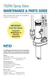
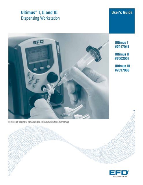
Ultimus I, <strong>II</strong> <strong>and</strong> <strong>II</strong>I<br />
<strong>Dispensing</strong> <strong>Workstation</strong><br />
Electronic pdf files of <strong>EFD</strong> manuals are also available at www.efd-inc.com/manuals<br />
User’s Guide<br />
Ultimus I<br />
#7017041<br />
Ultimus <strong>II</strong><br />
#7002003<br />
Ultimus <strong>II</strong>I<br />
#7017068<br />
A NORDSON COMPANY<br />
®
2<br />
Introduction<br />
Welcome to the Ultimus I, <strong>II</strong> <strong>and</strong> <strong>II</strong>I, the most complete dispensing system on the market. This User’s<br />
Guide will help you maximize the usefulness of your new workstation.<br />
Please spend a few minutes to become familiar with the controls <strong>and</strong> features. Follow our recommended<br />
testing procedures. Review the helpful information we have included, which is based on more than<br />
30 years of industrial dispensing experience.<br />
Most questions you will have are answered in this guide. However, if you need assistance, please do<br />
not hesitate to contact <strong>EFD</strong> or your authorized <strong>EFD</strong> distributor.<br />
In the USA, call 800-556-3484 between 8:30 a.m. <strong>and</strong> 5:30 p.m. Eastern time.<br />
In Europe, call +44 (0) 1582 666334.<br />
In Asia, call +86 (21) 3866 9006.<br />
In all other areas, call your authorized <strong>EFD</strong> distributor or +1-401-431-7000.<br />
The <strong>EFD</strong> Pledge<br />
We pledge that you will be completely satisfied with our products. We endeavor to ensure that every<br />
<strong>EFD</strong> product is produced to our no-compromise quality st<strong>and</strong>ards.<br />
If you feel that you are not receiving all the support you require, or if you have any questions or<br />
comments, I invite you to write or call me personally.<br />
Our goal is to build not only the finest equipment <strong>and</strong> components, but also to build long-term customer<br />
relationships founded on superb quality, service, value <strong>and</strong> trust.<br />
Peter Lambert, President
Safety . . . . . . . . . . . . . . . . . . . . . . . . . . . . . . . . . . . . . . . . . . . . . . . . . . . . . . . . . . . . . . 4<br />
Getting Started . . . . . . . . . . . . . . . . . . . . . . . . . . . . . . . . . . . . . . . . . . . . . . . . . . . . . . . . 6<br />
Specifications. . . . . . . . . . . . . . . . . . . . . . . . . . . . . . . . . . . . . . . . . . . . . . . . . . . . . . . . . 7<br />
Features <strong>and</strong> Controls . . . . . . . . . . . . . . . . . . . . . . . . . . . . . . . . . . . . . . . . . . . . . . . . 8-10<br />
Back Panel . . . . . . . . . . . . . . . . . . . . . . . . . . . . . . . . . . . . . . . . . . . . . . . . . . . . . . 11<br />
Filling the Syringe Barrel . . . . . . . . . . . . . . . . . . . . . . . . . . . . . . . . . . . . . . . . . . . . . . . 13<br />
Vacuum Control . . . . . . . . . . . . . . . . . . . . . . . . . . . . . . . . . . . . . . . . . . . . . . . . . . . . . . 14<br />
Syringe Barrel Loaders . . . . . . . . . . . . . . . . . . . . . . . . . . . . . . . . . . . . . . . . . . . . . . . . . 15<br />
Test Procedures . . . . . . . . . . . . . . . . . . . . . . . . . . . . . . . . . . . . . . . . . . . . . . . . . . . . . . 16<br />
Memory . . . . . . . . . . . . . . . . . . . . . . . . . . . . . . . . . . . . . . . . . . . . . . . . . . . . . . . . . . . . 18<br />
Menu Functions . . . . . . . . . . . . . . . . . . . . . . . . . . . . . . . . . . . . . . . . . . . . . . . . . . . . . . 20<br />
Input/Output Connection . . . . . . . . . . . . . . . . . . . . . . . . . . . . . . . . . . . . . . . . . . . . . . . . 22<br />
Schematic . . . . . . . . . . . . . . . . . . . . . . . . . . . . . . . . . . . . . . . . . . . . . . . . . . . . . . . . . . 23<br />
Troubleshooting . . . . . . . . . . . . . . . . . . . . . . . . . . . . . . . . . . . . . . . . . . . . . . . . . . . . . . 24<br />
Helpful Hints. . . . . . . . . . . . . . . . . . . . . . . . . . . . . . . . . . . . . . . . . . . . . . . . . . . . . . . . . 25<br />
Productivity Tools . . . . . . . . . . . . . . . . . . . . . . . . . . . . . . . . . . . . . . . . . . . . . . . . . . . . . 26<br />
Warranty . . . . . . . . . . . . . . . . . . . . . . . . . . . . . . . . . . . . . . . . . . . . . . . . . . . . . Back Cover<br />
IMPORTANT SAFETY INFORMATION<br />
All <strong>EFD</strong> disposable components, including syringe barrels, cartridges, pistons, tip caps, end caps,<br />
<strong>and</strong> dispense tips, are precision engineered for one-time use. Attempting to clean <strong>and</strong> re-use<br />
components will compromise dispensing accuracy <strong>and</strong> may increase the risk of personal injury.<br />
Always wear appropriate protective equipment <strong>and</strong> clothing suitable for your dispensing<br />
application.<br />
Do not exceed maximum operating pressure of 100 psi (7.0kg/cm2).<br />
Do not heat syringe barrels or cartridges to a temperature greater than 100°F (38°C).<br />
Dispose of components according to local regulations after one-time use.<br />
Do not clean components with strong solvents (e.g. MEK, Acetone, THF).<br />
Cartridge retainer systems <strong>and</strong> barrel loaders should be cleaned with mild detergents only.<br />
To prevent fluid waste, use <strong>EFD</strong> SmoothFlowTM pistons.<br />
This manual is for the express <strong>and</strong> sole use of <strong>EFD</strong> dispenser purchasers <strong>and</strong> users, <strong>and</strong> no portion of it may be reproduced in any form.<br />
Contents<br />
3
4<br />
Safety<br />
Introduction<br />
Read <strong>and</strong> follow these safety instructions. Task- <strong>and</strong> equipment-specific warnings, cautions <strong>and</strong><br />
instructions are included in equipment documentation where appropriate.<br />
Qualified Personnel<br />
Equipment owners are responsible for making sure that <strong>EFD</strong> equipment is installed, operated <strong>and</strong><br />
serviced by qualified personnel. Qualified personnel are those employees or contractors who are<br />
trained to safely perform their assigned tasks. They are familiar with all relevant safety rules <strong>and</strong><br />
regulations, <strong>and</strong> are physically capable of performing their assigned tasks.<br />
Intended Use<br />
Use of <strong>EFD</strong> equipment in ways other than those described in the documentation supplied with the<br />
equipment may result in injury to persons or damage to property.<br />
Some examples of unintended use of equipment include<br />
Using incompatible materials Using incompatible or damaged parts<br />
Making unauthorized modifications Using unapproved auxiliary equipment<br />
Removing or bypassing safety guards or interlocks Operating equipment in excess of maximum ratings<br />
Regulations <strong>and</strong> Approvals<br />
Make sure all equipment is rated <strong>and</strong> approved for the environment in which it is used. Any<br />
approvals obtained for <strong>EFD</strong> equipment will be voided if instructions for installation, operation <strong>and</strong><br />
service are not followed.<br />
Personal Safety<br />
To prevent injury follow these instructions.<br />
Do not operate or service equipment unless you are qualified.<br />
Do not operate equipment unless safety guards, doors or covers are intact <strong>and</strong> automatic<br />
interlocks are operating properly. Do not bypass or disarm any safety devices.<br />
If you receive even a slight electrical shock, shut down all electrical or equipment immediately.<br />
Do not restart the equipment until the problem has been identified <strong>and</strong> corrected.<br />
Obtain <strong>and</strong> read Material Safety Data Sheets (MSDS) for all materials used. Follow the<br />
manufacturer’s instructions for safe h<strong>and</strong>ling <strong>and</strong> use of materials, <strong>and</strong> use recommended<br />
personal protection devices.<br />
To prevent injury, be aware of less-obvious dangers in the workplace that often cannot be<br />
completely eliminated, such as hot surfaces, sharp edges, energized electrical circuits <strong>and</strong> moving<br />
parts that cannot be enclosed or otherwise guarded for practical reasons.<br />
This equipment is for indoor use only.<br />
Use only the power adapter provided with the unit. Contact <strong>EFD</strong> to purchase a replacement adapter.<br />
Always keep dispensing end of syringe barrel pointed away from your face <strong>and</strong> towards the work<br />
piece. Store the syringe barrel in an appropriate holder when not in use.<br />
Caution: Use <strong>EFD</strong> filter/muffler #7016875 or wear adequate ear protection when operating the<br />
vacuum in close proximity for a prolonged period of time.<br />
Caution: A pressure regulator of 0 to 100 psi is intended to be provided before connecting unit<br />
to the air supply.
Fire Safety<br />
To avoid a fire or explosion, follow these instructions.<br />
Shut down all equipment immediately if you notice static sparking or arcing. Do not restart the<br />
equipment until the cause has been identified <strong>and</strong> corrected.<br />
Do not smoke, weld, grind or use open flames where flammable materials are being used or<br />
stored.<br />
Provide adequate ventilation to prevent dangerous concentrations of volatile particles or vapors.<br />
Refer to local codes or your material MSDS for guidance.<br />
Do not disconnect live electrical circuits when working with flammable materials. Shut off power<br />
at a disconnect switch first to prevent sparking.<br />
Know where emergency stop buttons, shutoff valves <strong>and</strong> fire extinguishers are located.<br />
Clean, maintain, test <strong>and</strong> repair equipment according to the instructions in your equipment<br />
documentation.<br />
Use only replacement parts that are designed for use with original equipment. Contact your <strong>EFD</strong><br />
representative for parts information <strong>and</strong> advice.<br />
Action in the Event of a Malfunction<br />
If a system or any equipment in a system malfunctions, shut off the system immediately <strong>and</strong> perform<br />
the following steps:<br />
Disconnect <strong>and</strong> lock out system electrical power.<br />
Identify the reason for the malfunction <strong>and</strong> correct it before restarting the system.<br />
Disposal<br />
Dispose of equipment <strong>and</strong> materials used in operation <strong>and</strong> servicing according to local <strong>and</strong> national<br />
codes.<br />
RoHS标准相关声明 (China RoHS Hazardous Material Declaration)<br />
产品名称 有害物质及元素<br />
Part Name Toxic or Hazardous Substances <strong>and</strong> Elements<br />
铅 汞 镉 六价铬 多溴联苯 多溴联苯醚<br />
Lead Mercury Cadmium Hexavalent Polybrominated Polybrominated<br />
Chromium Biphenyls Diphenyl Ethers<br />
(Pb) (Hg) (Cd) (Cr6) (PBB) (PBDE)<br />
金属转接头 X O O O O O<br />
All Brass Fittings<br />
O: 表示该产品所含有的危险成分或有害物质含量依照EIP-A, EIP-B, EIP-C<br />
的标准低于SJ/T11363-2006 限定要求。<br />
O: Indicates that this toxic or hazardous substance contained in all the homogeneous materials for this part,<br />
according to EIP-A, EIP-B, EIP-C is below the limit requirement in SJ/T11363-2006.<br />
X: 表示该产品所含有的危险成分或有害物质含量依照EIP-A, EIP-B, EIP-C<br />
的标准高于SJ/T11363-2006 限定要求.<br />
X: Indicates that this toxic or hazardous substance contained in all the homogeneous materials for this part,<br />
according to EIP-A, EIP-B, EIP-C is above the limit requirement in SJ/T11363-2006.<br />
Safety<br />
5
6<br />
Getting<br />
Started<br />
The Ultimus workstation is designed to provide complete process control for precise, repeatable fluid<br />
dispensing.<br />
Key features include<br />
All-digital, multi-function display with simultaneous readout of air pressure, time, vacuum,<br />
deposit shot count <strong>and</strong> time of day<br />
Unique air management reservoir <strong>and</strong> high-speed solenoid system for consistent, repeatable<br />
deposits<br />
Time increment adjustments as small as 0.0001 seconds for precise deposit control<br />
<strong>Workstation</strong> panels to hold a variety of useful accessories, including light, ergonomic syringe<br />
barrel holder, magnifier <strong>and</strong> more<br />
First Steps<br />
First: Place the dispenser in your work area. The Ultimus is equipped with “stay put” rubber pads. It<br />
can be placed on the benchtop or any flat surface.<br />
Second: Connect to power <strong>and</strong> air supplies, <strong>and</strong> program the unit. For step-by-step setup<br />
instructions, see the Ultimus Quick Start Guide.<br />
Third: Now is a good time to activate your Ten Year Warranty. Please register your warranty online at<br />
www.efd-inc.com/warranty/ten. Or if you prefer, follow the instructions in the enclosed “Welcome”<br />
letter to contact your area <strong>EFD</strong> representative.
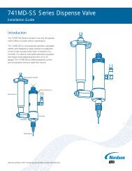
Cabinet size: 14.3 W x 18.1 H x 17.3 D cm (5.63 x 7.12 x 6.82")<br />
Weight: 2.3 kg (5.0 lb)<br />
Power adapter:<br />
AC input: 100-240 VAC(+/-10%) ~, 50/60Hz, 0.6A<br />
DC output: 24 VDC @ 1.04A<br />
End-of-cycle feedback circuits: 5 to 24 VDC; 100mA maximum<br />
Initiate circuits: Foot pedal, finger switch or 5 to 24 VDC signal<br />
Cycle rate: Exceeds 600 cycles per minute<br />
Time range: Programmable from 0.0001 to 999.9999 seconds<br />
Ambient operating conditions:<br />
Temperature: 5°C to 45°C (41°F to 113°F)<br />
Humidity: 85% RH at 30°C non-condensing<br />
Height above sea level: 2000 meters max (6,562 feet)<br />
Meets or exceeds CE <strong>and</strong> CSA requirements<br />
Ultimus I (7017041)<br />
Air input: 80 to 100 psi (5.5 to 6.9 bar)<br />
Air output: 0 to 100 psi (0 to 6.9 bar)<br />
Ultimus <strong>II</strong> (7002003)<br />
Air input: 80 to 100 psi (5.5 to 6.9 bar)<br />
Air output: 0 to 15 psi (0 to 1.0 bar)<br />
Ultimus <strong>II</strong>I (7017068)<br />
Air input: 80 to 100 psi (5.5 bar to 6.9 bar)<br />
Air output: 0 to 5 psi (0 to 0.34 bar)<br />
Note: Specifications <strong>and</strong> technical details are subject to change without prior notification.<br />
180.8 mm<br />
7.12 "<br />
+<br />
143.0 mm<br />
5.63 "<br />
120.6 mm<br />
4.75 "<br />
+<br />
173.2 mm<br />
6.82 "<br />
Specifications<br />
159.5 mm<br />
6.28 "<br />
7
8<br />
Features &<br />
Controls:<br />
Front Panel<br />
Dispense Mode<br />
When powered for the first time, the Ultimus Home screen displays in TIMED<br />
mode. Otherwise, it displays in the mode last used.<br />
You can verify what mode you’re in by checking the top left corner of the<br />
display screen. It will be TIMED, TEACH, STEADY or MEMORY.<br />
You can return to TIMED mode from TEACH or STEADY by pressing<br />
TIMED in the bottom right corner of the display.<br />
You can return to TIMED mode from MEMORY by pressing MENU, then<br />
selecting TIMED.<br />
See the appropriate section below for details on each dispense mode.<br />
Dispense Time<br />
dispense time<br />
vacuum pullback<br />
power<br />
display navigation<br />
mode indicator<br />
cycle counter<br />
time of day<br />
Dispense time, shown with an hourglass icon, displays from 000.0001 to 999.9999 seconds.<br />
Follow these steps to set the dispense time.<br />
Begin in TIMED mode.<br />
Press the left/right arrows to highlight the first number you want to change.<br />
Press the up/down arrows to set the time. Or if you prefer, you can also<br />
use the timer dial (top right knob) to set the time.<br />
Repeat as needed to adjust the other numbers in the dispense time row.<br />
dispense pressure<br />
menu<br />
multi-function controls<br />
data/time control<br />
output air<br />
pressure regulator vacuum regulator<br />
See the Ultimus Icon Guide, included with your dispensing system, if you are working<br />
in Chinese, Japanese, or Korean. Sample icons:<br />
(Timed) (Steady) (Teach) (Menu) (Select) (Home)<br />
Timed<br />
Mode
Air Pressure<br />
Air pressure is displayed in psi. See page 20 to change the display of pressure from psi to bar or<br />
kPa. It is shown with the icon of an arrow pushing into a syringe barrel. Follow these steps to set air<br />
pressure.<br />
Pull the air pressure regulator knob out to unlock it (bottom left knob).<br />
Turn the knob clockwise to the desired pressure setting.<br />
To reduce pressure, turn the knob counterclockwise until the display<br />
reads a lower pressure than needed. Then increase the pressure until you<br />
reach the correct setting.<br />
Push the knob in to lock the pressure setting.<br />
For Ultimus I, <strong>II</strong> <strong>and</strong> <strong>II</strong>I units: Set plant air supply within 80 to 100 psi (5.5 to 6.9 bar).<br />
Caution: A pressure regulator of 0 to 100 psi is intended to be provided before connecting unit to<br />
the air supply.<br />
Vacuum<br />
Vacuum is displayed in inH 2O (inches of water). See page 20 to change the display of vacuum from<br />
inH 2O to inHg, kPa, mmHg, or Torr. It is shown with the icon of an arrow<br />
pulling out of a syringe barrel. Follow these steps to set vacuum pressure.<br />
Pull the vacuum regulator knob out to unlock it (bottom right knob).<br />
Turn the knob clockwise to the desired setting. You can adjust the<br />
vacuum in increments of 0.1 inH2O. Push the knob in to lock the vacuum setting.<br />
Clock<br />
Caution: Use <strong>EFD</strong> filter/muffler #7016875 or wear adequate ear<br />
protection when operating the vacuum in close proximity for a prolonged period of time.<br />
A real time clock is displayed in the top right corner. Follow these steps to set the clock.<br />
Press MENU.<br />
Press the down arrow to highlight SET CLOCK.<br />
Press SELECT.<br />
Press the left/right arrow to highlight the number to change.<br />
Press the up/down arrow to adjust the time. Or use the timer dial (top<br />
right knob) to adjust the time or toggle between AM (morning) <strong>and</strong> PM<br />
(afternoon/evening).<br />
Press SAVE. This saves the time <strong>and</strong> automatically returns you to the<br />
Home screen.<br />
Features &<br />
Controls:<br />
Front Panel<br />
9
10<br />
Features &<br />
Controls:<br />
Front Panel<br />
Power<br />
Press the power button to turn the unit on. An <strong>EFD</strong> logo will briefly appear before the Home screen<br />
displays. The Ultimus will go into sleep mode when it’s inactive for more than 90 minutes. Simply<br />
press any button or the foot pedal to reactivate the screen.<br />
Menu<br />
You can access the menu screen by pressing MENU. From here press the up/down <strong>and</strong> left/right<br />
arrows to select from a variety of screens, including:<br />
TIMED TEACH MEMORY<br />
CLEAR COUNT UNITS OF PRESSURE UNITS OF VACUUM<br />
SECURITY LANGUAGE SAVE JOB<br />
SET CLOCK INFO<br />
See page 20 for details on various Menu functions.<br />
Shot Count<br />
The shot count is displayed in the top center section of the display screen. It displays the number of<br />
deposits that have been dispensed. Follow these steps to reset the shot count.<br />
Press MENU.<br />
Press the down arrow to highlight CLEAR COUNT.<br />
Press SELECT. This resets the shot count to 0 <strong>and</strong> automatically returns you to the Home screen.<br />
Timed Mode<br />
In TIMED mode, the Ultimus will dispense a single deposit each time you press the foot pedal or<br />
finger switch. Deposit size is based on dispense time <strong>and</strong> pressure settings shown on the display.<br />
Steady Mode<br />
In STEADY mode you can dispense for as long as you press the foot pedal or finger switch. From<br />
TIMED mode, press STEADY. This toggles the display so that the top left corner is now selected for<br />
STEADY mode. See Initial Test Procedures, page 16, for more details on STEADY mode.<br />
Teach Mode<br />
In TEACH mode you can “teach” the deposit based on physical size. Begin in the Home screen for<br />
TIMED mode. Press TEACH. This toggles the display so that the top left corner is now selected for<br />
TEACH mode. See Initial Test Procedures, page 16, for more details on TEACH mode.<br />
Output Air Port<br />
The Ultimus features two output air ports. You can connect the Optimum adapter assembly to the<br />
port on the front panel or the back panel, whichever is most convenient.
Power<br />
Input Port<br />
Power Input Port<br />
The power input port is located at the top left corner of the Ultimus. The Ultimus power pack<br />
automatically adjusts for 100 to 240 VAC.<br />
Use only the universal power pack provided with the Ultimus workstation. The unit is shipped with<br />
four power plugs (one USA <strong>and</strong> three international plugs) <strong>and</strong> a 5.9 ft (1800 mm) length power cord.<br />
Connect the DC plug from the cord into the Ultimus power input port.<br />
Connect the power cord into your local power source.<br />
Communication Port<br />
Communication<br />
Port<br />
Input/<br />
Output<br />
The Ultimus communication port, located on the top row of ports, is for <strong>EFD</strong> use only.<br />
Input/Output 8 Pin Interface Connector<br />
Auxiliary<br />
Port<br />
Exhaust Output air Input air<br />
Foot Pedal /<br />
Finger Switch<br />
Input/output features are used when the Ultimus is interfaced with external control circuits.<br />
The 8 pin connector is located on the top row of ports. See page 22 for details.<br />
An End-of-Cycle signal, in the form of a solid-state switch, closes upon completion of the<br />
dispense cycle.<br />
Features &<br />
Controls:<br />
Back Panel<br />
11
12<br />
Features &<br />
Controls:<br />
Back Panel<br />
Auxiliary Port<br />
The auxiliary port, a 6 pin mini DIN connection, is located on the top row of ports. It is designed to<br />
power the Ultimus accessories such as the workstation lamp. The auxiliary port is interchangeable<br />
with the foot pedal / finger switch port.<br />
Foot Pedal / Finger Switch Port<br />
The switch port, a 6 pin mini DIN connection, is located on the top right corner of the Ultimus. It is<br />
used to connect the foot pedal or finger switch that activates the dispense cycle. The switch port is<br />
interchangeable with the auxiliary port, described above. Be sure to align the foot pedal or finger<br />
switch cord connector so that arrow on the connector is on top.<br />
Exhaust Port<br />
The exhaust port is the larger 8 mm pneumatic fitting located at the bottom left corner of the<br />
Ultimus workstation.<br />
If needed, you can connect a cleanroom filter muffler to filter output air to meet Fed 209-B<br />
(0.5 micron particulates). Specify #7017049.<br />
Caution: Use <strong>EFD</strong> filter/muffler #7016875 or wear adequate ear protection when operating the<br />
vacuum in close proximity for a prolonged period of time.<br />
Air Output Port<br />
The Ultimus features two air output ports to provide regulated air pressure to the syringe barrel. Both<br />
ports have quick-connect fittings <strong>and</strong> are interchangeable, sharing the same air source.<br />
You can connect to the port on the front panel or the back panel, whichever is most convenient.<br />
On the back panel, the air output is the center port on the bottom row.<br />
Push in the black quick-connect from the <strong>EFD</strong> adapter assembly to the air output port <strong>and</strong> twist to<br />
lock. Note: air does not flow through the port until a quick-connect is installed.<br />
Air Input Port<br />
The air input port is the smaller pneumatic fitting (6 mm) located at the bottom right corner of the<br />
Ultimus workstation.<br />
Push one end of the air input hose into the input fitting on the back of the Ultimus. An 8 ft (2.4 mm)<br />
air hose is provided.<br />
Connect the other end of the air input hose to your plant air supply. A st<strong>and</strong>ard 1/4-inch NPT<br />
fitting is included with your unit.<br />
Note: clean, dry filtered factory air is required to meet warranty. If your air supply is not filtered,<br />
order the five-micron filter regulator specify #7002002.<br />
Warning! Bottled nitrogen can be used. If high pressure bottled air or nitrogen is used, a high<br />
pressure regulator must be installed on the bottle <strong>and</strong> set at 100 psi (6.9 bar) maximum. In this<br />
instance, the #7002002 filter regulator is not required.<br />
Caution: A pressure regulator of 0 to 100 PSI is intended to be provided before connecting unit to<br />
the air supply.
Caution: Do not completely fill syringe barrels. The optimum fill is a maximum 2/3 of the barrel<br />
capacity <strong>and</strong> 1/2 of the barrel capacity when using the <strong>EFD</strong> blue LV Barrier piston.<br />
For best results, we strongly recommend that you use a piston as part of your dispensing system.<br />
The white <strong>EFD</strong> SmoothFlow piston is<br />
appropriate for most fluids <strong>and</strong> has<br />
several advantages.<br />
First, vacuum adjustment is less<br />
sensitive.<br />
Second, the piston prevents fumes<br />
from the fluid being exhausted into<br />
the work environment.<br />
Third, the piston prevents fluid<br />
backflow into the dispenser if the<br />
syringe barrel is inadvertently turned<br />
upside down.<br />
Fourth, the piston makes it easy <strong>and</strong><br />
safe to change tips without dripping.<br />
For watery solvents <strong>and</strong> cyanoacrylates,<br />
request the blue <strong>EFD</strong> LV Barrier piston,<br />
available in 3cc, 10cc <strong>and</strong> 30cc sizes. If<br />
you are dispensing an RTV silicone <strong>and</strong><br />
find that the piston bounces <strong>and</strong> causes<br />
stringing, request the <strong>EFD</strong> orange, flat wall<br />
piston.<br />
Filling procedure for pourable low <strong>and</strong> medium<br />
viscosity fluids<br />
If the fluid you are dispensing is pourable, take the syringe barrel, twist on<br />
an orange tip cap <strong>and</strong> pour your fluid in. Insert a white SmoothFlow piston<br />
<strong>and</strong> carefully press down until it contacts the fluid. The syringe barrel is<br />
now ready for use.<br />
Filling procedure for thick fluids<br />
Remember<br />
For best results, <strong>EFD</strong> strongly recommends the<br />
use of a piston as part of your dispensing system.<br />
SmoothFlow piston prevents fluid backflow.<br />
If you choose to not use a piston when dispensing<br />
thin fluids, remember these important points.<br />
Do not tip the barrel upside down or lay<br />
flat. This will cause the liquid to run into<br />
the dispenser.<br />
If your fluid is thick or non-leveling, you can spoon it into the syringe barrel<br />
with a spatula. Or, if the fluid comes packed in a 1/10 gallon (300 ml)<br />
cartridge, try loading the barrel with a caulking gun. Then, press the<br />
SmoothFlow piston to move the fluid to the bottom of the syringe barrel <strong>and</strong><br />
remove trapped air.<br />
Trapped air in thick fluids can lead to drooling <strong>and</strong> oozing. Also, repetitive air<br />
cycles can bore tunnels through non-leveling fluids, causing spitting <strong>and</strong><br />
inconsistent deposits. The SmoothFlow piston eliminates these problems. It<br />
prevents tunneling by providing a barrier to the pulsed-air cycles. And it<br />
prevents oozing by responding to the pressure of trapped air with a slight<br />
suck-back movement after the dispense cycle.<br />
caulking gun<br />
Open<br />
Closed<br />
Fumes cannot<br />
escape.<br />
Filling<br />
the Syringe<br />
Barrel<br />
No air gap when<br />
using the<br />
SmoothFlow<br />
piston.<br />
When changing tips or<br />
attaching a tip cap,<br />
snap the safety clip<br />
completely closed to<br />
prevent any dripping or<br />
bubbling.<br />
SmoothFlow piston<br />
2/3 maximum fill<br />
2/3 maximum fill<br />
13
14<br />
Filling<br />
the Syringe<br />
Barrel<br />
Vacuum<br />
Control<br />
Filling procedure for watery fluids <strong>and</strong> vacuum control<br />
The Ultimus vacuum regulator allows low viscosity fluids, even water, to be consistently dispensed<br />
without dripping between cycles. A vacuum is exerted above the fluid in the barrel to prevent<br />
dripping. For medium to high viscosity fluids, the recommended vacuum setting is 0.0.<br />
If you are dispensing watery solvents, cyanoacrylates or anaerobics, request the blue LV Barrier<br />
piston <strong>and</strong> follow these steps to fill the syringe barrel <strong>and</strong> set the vacuum control.<br />
1. Twist a blue tip cap onto an empty syringe barrel <strong>and</strong><br />
pour your fluid in. Insert the blue LV Barrier piston. Allow<br />
an air gap between piston <strong>and</strong> fluid as shown. (If you<br />
are using the SmoothFlow piston, push the white piston<br />
down until it comes in contact with the fluid.)<br />
LV Barrier<br />
2. Attach the syringe to the <strong>EFD</strong> adapter assembly.<br />
Air gap<br />
3. Snap the safety clip tightly closed to prevent any<br />
dripping.<br />
4. Remove the tip cap <strong>and</strong> attach a precision dispense tip.<br />
5. Set air pressure at 2 psi (0.1 bar).<br />
6. From TIMED mode, press STEADY.<br />
7. With the syringe barrel pointing down over a container, unsnap the safety clip. Press <strong>and</strong> hold<br />
the foot pedal or finger switch to fill the tip.<br />
8. As a drop begins to form at the end of the tip, slowly turn the vacuum regulator knob clockwise<br />
to stop the drip. Wipe the tip <strong>and</strong> adjust vacuum as necessary.<br />
9. Return to TIMED mode.<br />
10. Rest the tip on the Dot St<strong>and</strong>ards sheet. Press the foot pedal <strong>and</strong> release. Check the dot size.<br />
Increase or decrease by adjusting pressure or time as needed.<br />
Caution: Use <strong>EFD</strong> filter/muffler #7016875 or wear adequate ear protection when operating the<br />
vacuum in close proximity for a prolonged period of time.<br />
Note: For best results when dispensing watery-thin fluids, <strong>EFD</strong> recommends the use of the Vacuum<br />
Suck-Back Filter Trap #7017115. This is guaranteed to prevent fluid from being sucked back into<br />
the dispenser. See page 26 for a sample drawing, or call <strong>EFD</strong> or email info@efd-inc.com for details.
Syringe Barrel Loading Alternatives<br />
<strong>EFD</strong> offers productive alternatives to traditional syringe barrel loading methods. Here are a few<br />
suggestions that can help keep your work area clean, save time <strong>and</strong> reduce the chance of entrapped<br />
air in the fluid.<br />
1. You could use the #7022445 Atlas Filling System. Pack the fluid into the 12 ounce cartridge<br />
as shown. Then place the pre-filled cartridge into the barrel loader. Using air pressure, the barrel<br />
loader fills the syringe barrel (with a piston installed) from the bottom up.<br />
If the fluid comes packed in a 1/10 gallon (300 ml) caulking type cartridge, use the <strong>EFD</strong><br />
#7022452 filling system.<br />
For fast, volumetric filling, #7022068 Atlas Filling System, is an accurate, easy <strong>and</strong> fast system<br />
to fill syringe barrels.<br />
2. If you receive frozen epoxies or other fluids in medical type syringes with a manual plunger,<br />
request the <strong>EFD</strong> luer-to-luer fitting #7016862 to transfer the material.<br />
Please contact an <strong>EFD</strong> fluid application specialist for additional assistance.<br />
Filling the cartridge<br />
for the Atlas Filling<br />
System<br />
#7022445 Atlas Filling System<br />
Specify #7022452 for pre-filled<br />
1/10 gal (300 ml) caulking tubes<br />
Barrel Rack<br />
#7022411 for 3cc & 5cc barrels<br />
#7022429 for 10cc, 30cc <strong>and</strong> 55cc barrels<br />
#7016862 Luer-to-luer fitting<br />
Syringe<br />
Barrel<br />
Loaders<br />
#7022068 Atlas Filling System<br />
15
16<br />
Initial Test<br />
Procedures<br />
Deposit size is controlled by time, pressure <strong>and</strong> tip size.<br />
Please follow these instructions to test each function. Use the convenient Dot St<strong>and</strong>ards sheet<br />
included in your dispensing system kit.<br />
Setup for Testing<br />
1. Attach an <strong>EFD</strong> syringe barrel filled with your<br />
assembly fluid to the adapter assembly as<br />
shown.<br />
2. Keep the vacuum set at 0.0 during initial<br />
testing. (If you are dispensing a watery fluid,<br />
see Vacuum Control, page 14).<br />
3. Replace the blue tip cap with an <strong>EFD</strong><br />
precision dispense tip.<br />
4. Slide the syringe barrel into the h<strong>and</strong> grip. Snap in place.<br />
5. Run through the following tests to demonstrate the ease at which deposit sizes can be<br />
established using the various dispense modes.<br />
Testing in Steady Mode<br />
Select STEADY mode.<br />
Pull the air pressure regulator knob out until it clicks into the unlocked position. Start with<br />
pressure set to 0 psi (0.0 bar).<br />
Press <strong>and</strong> hold the foot pedal or finger switch.<br />
Slowly, turn the pressure knob clockwise until your fluid begins to dispense out of the tip in a<br />
controlled flow (not too fast, not too slow).<br />
Push the air pressure knob in to lock setting.<br />
Remember - always bring the<br />
tip in contact with the work<br />
surface at the illustrated angle.<br />
After the tip is in position, press<br />
the foot pedal. Release pedal <strong>and</strong><br />
remove tip by lifting straight up.<br />
45º<br />
Correct angle for<br />
consistent deposits.
Testing in Timed Mode<br />
Follow steps in “Testing in Steady Mode” to purge your dispensing tip with fluid.<br />
Change to TIMED mode.<br />
Set time to 000.0250 seconds.<br />
Rest the dispense tip on the Dot St<strong>and</strong>ards sheet.<br />
Press the foot pedal (or finger switch) to activate the dispense cycle. Note: the pedal only needs<br />
to be pressed for a moment. The complete time will run once you activate the dispense cycle.<br />
Changing the time changes the deposit size. If your dot is too small, increase the dispense<br />
time to increase the deposit size. If your dot is too large, decrease the dispense time to<br />
decrease your deposit size.<br />
Testing in Teach Mode<br />
Follow steps in “Testing in Steady Mode” to purge your dispensing tip with fluid.<br />
Change to TEACH mode.<br />
Rest the dispense tip on the Dot St<strong>and</strong>ards sheet.<br />
Press the foot pedal to establish your dot size. Tapping the foot pedal repeatedly will have a<br />
cumulative effect on the dot size <strong>and</strong> dispense time.<br />
Continue to press the foot pedal until you achieve the correct deposit size.<br />
Save the dispense time setting you just created by pressing SAVE. This automatically exits<br />
TEACH mode <strong>and</strong> returns you to TIMED mode.<br />
If needed, press CLEAR to start over.<br />
If you have any questions at this point, please call us now.<br />
In the USA, call 800-556-3484 between 8:30 a.m. <strong>and</strong> 5:30 p.m. Eastern time.<br />
In Europe, call +44 (0) 1582 666334.<br />
In Asia, call +86 (21) 3866 9006.<br />
In all other areas, call your authorized <strong>EFD</strong> distributor or +1-401-431-7000.<br />
Initial Test<br />
Procedures<br />
17
18<br />
Memory<br />
The Ultimus dispensing workstation allows you to store the dispense time, pressure <strong>and</strong> vacuum<br />
settings for up to 16 different job programs. Programs are saved even with power removed <strong>and</strong> will<br />
remain in storage unless changed or erased intentionally.<br />
Job programs are identified as Memory 1 through Memory 16.<br />
Note: Dispense time is automatically adjusted when you select an individual job program. Settings for<br />
pressure <strong>and</strong> vacuum are stored <strong>and</strong> can be displayed but you need to manually adjust the pressure<br />
<strong>and</strong> vacuum regulator knobs to match the stored settings for these values.<br />
To Save a Job Program<br />
1. From TIMED or TEACH mode, set the dispense time, air pressure <strong>and</strong> vacuum settings to<br />
create a correct deposit size. When you are in TEACH mode, press SAVE after you create your<br />
settings, then return to TIMED mode.<br />
2. Press MENU. Use the up/down arrows to highlight SAVE JOB. Press SELECT.<br />
3. Use the up/down arrows to select the correct job program in which to save these settings<br />
(example, Memory 1 or Memory 2). Remember: to prevent accidental data loss, review the<br />
contents of each job program before selecting <strong>and</strong> storing a new job into memory.<br />
4. Press SAVE. This automatically saves the settings in the job program <strong>and</strong> returns you to the<br />
Home screen.<br />
5. Press the foot pedal or finger switch to activate the dispense cycle. The Ultimus workstation will<br />
make the deposit based on the settings in the selected job program.<br />
To Work in a Saved Job Program<br />
1. Press MENU. Use the up/down arrows to highlight MEMORY. Press SELECT.<br />
2. Use the up/down arrows to scroll through the individual jobs until you reach the correct Memory<br />
number.<br />
3. Press <strong>and</strong> hold SETTINGS to see the stored pressure <strong>and</strong> vacuum settings for the job.<br />
Remember: Dispense time automatically adjusts when you select a job program. Releasing the<br />
Settings button displays the current values for pressure <strong>and</strong> vacuum, not the stored values. To<br />
retrieve the stored values, manually adjust air pressure <strong>and</strong> vacuum, based on the pressure <strong>and</strong><br />
vacuum shown when you press Settings.<br />
4. Press the foot pedal or finger switch to activate the dispense cycle. The Ultimus will<br />
automatically make the deposit based on the settings in the selected job program.<br />
5. To escape from Memory, press MENU. Then press TIMED to return to the Home screen. At this<br />
point, you are still in the current memory setting for the previous job program, but you are free<br />
to change time, pressure <strong>and</strong> vacuum without impacting the stored settings in memory.
To Edit or Clear a Saved Job<br />
Follow these steps to make changes to an existing job.<br />
1. Press MENU. Use the up/down arrows to highlight MEMORY. Press SELECT.<br />
2. Use the up/down arrows to select the correct job program to edit (Memory 1, Memory 2, etc.).<br />
3. If you need to review the stored values for pressure <strong>and</strong> vacuum, press <strong>and</strong> hold SETTINGS.<br />
You can adjust the pressure <strong>and</strong> vacuum from this screen, or you can make adjustments from<br />
TIMED mode. However, note: you can only adjust the dispense time setting from the TIMED<br />
mode screen.<br />
4. Press MENU again.<br />
5. Press TIMED to return to TIMED mode in the selected program.<br />
6. Adjust the settings for dispense time, air pressure <strong>and</strong> vacuum as needed to achieve the correct<br />
deposit size.<br />
7. Press MENU.<br />
8. Use the up/down arrows to highlight SAVE JOB. Press SELECT.<br />
9. Use the up/down arrows to again select the correct job program.<br />
10. Press SAVE. This automatically saves the changed settings <strong>and</strong> returns you to the Home screen.<br />
Note: to clear all settings in a specific job program, simply set the time, pressure <strong>and</strong> vacuum to 0 in<br />
step 6 <strong>and</strong> follow the other steps as noted.<br />
Memory<br />
19
20<br />
Menu<br />
Functions<br />
You can access the menu screen by pressing MENU. From here press the up/down <strong>and</strong> left/right<br />
arrows to select from a variety of screens.<br />
Timed/Teach mode<br />
See pages 8-10 for details on the Ultimus dispense modes.<br />
Memory/Save Job<br />
See pages 18-19 for details on Memory <strong>and</strong> Save Job functions.<br />
Clear Count<br />
See page 10 for details on Shot Count <strong>and</strong> Clear Count functions.<br />
Units of Pressure/Units of Vacuum<br />
You can change the screen display of air pressure units from psi to bar or kPa, or for vacuum units<br />
from inH 2O to inHg, kPa, mmHg, or Torr. Follow these steps:<br />
Press MENU.<br />
Press the up/down arrow to highlight UNITS OF PRESSURE or UNITS OF VACUUM, then press<br />
SELECT.<br />
Press the up/down arrow to highlight the appropriate pressure or vacuum display option.<br />
Press SELECT again to make the change. This automatically returns you to the Home screen.<br />
Language<br />
You can change the screen display from English to another language. Follow these steps.<br />
Info<br />
Press MENU.<br />
Press the up/down arrow to highlight LANGUAGE, then press SELECT.<br />
Press the up/down arrow to highlight the appropriate option.<br />
Press SELECT again to make the change. This automatically returns you to the Home screen.<br />
The Info screen displays the Ultimus workstation’s serial number, model number <strong>and</strong> contact web<br />
site for customer service. To view INFO, press MENU, use the up/down arrow to highlight INFO, then<br />
press SELECT.
Security Code<br />
You can set a 4-digit password to prevent job changes by unauthorized users. This password locks<br />
out the ability to change dispense time, clear the shot count <strong>and</strong> modify settings in Memory. The<br />
password is required to access the Security screen. Unauthorized users get a Password Error<br />
message if they attempt to enter an invalid password.<br />
To select the functions to password protect<br />
Press MENU.<br />
Press the up/down arrow to highlight SECURITY, then press SELECT.<br />
For first time users, enter 0000 as the current password <strong>and</strong> press ENTER (0000 is the default<br />
setting).<br />
Press the up/down arrows to highlight the functions to protect (Memory, Shot Count <strong>and</strong> Time).<br />
Press SELECT to toggle between adding or deleting a checkmark next to each function. To<br />
protect the function from unauthorized changes, add the checkmark. To disable the password<br />
<strong>and</strong> allow any user to change settings, delete the checkmark.<br />
Press HOME to return to the Home screen.<br />
To change the password<br />
Press MENU.<br />
Press the up/down arrow to highlight SECURITY, then press SELECT.<br />
For first time users, enter 0000 as the current password <strong>and</strong> press ENTER (0000 is the default<br />
setting).<br />
Press PASSWORD.<br />
Press the left/right arrows to highlight the first number.<br />
Press the up/down arrows to set the number. Or if you prefer, you can also use the timer dial.<br />
Repeat to adjust the other numbers in the 4-digit code.<br />
Press ENTER. This puts you in the Security screen <strong>and</strong> automatically stores the new password.<br />
Press HOME to return to the Home screen.<br />
Menu<br />
Functions<br />
21
22<br />
Input/Output<br />
Connection<br />
Voltage Initiate Circuit<br />
The Ultimus workstation may be initiated with a 5 to 24 VDC signal across pins 1 <strong>and</strong> 2. The signal<br />
can be momentary (no less than 0.01 seconds) or maintained. A new cycle will begin once power is<br />
removed <strong>and</strong> then applied again.<br />
Mechanical Contact Initiate<br />
The Ultimus can be initiated via the closure of mechanical contacts such as a relay or switch using<br />
pins 7 <strong>and</strong> 8. Closure of the contacts can be momentary (no less than 0.01 seconds) or maintained.<br />
A new cycle will begin once the contacts are opened <strong>and</strong> then closed again.<br />
End-of-Cycle Feedback Circuit<br />
Upon completion of a dispense cycle, a solid state switch closes <strong>and</strong> remains closed until the next<br />
dispense cycle. Pins 3 <strong>and</strong> 4 of this circuit can be used to signal back to a host computer, start<br />
another device in sequence or initiate other operations that need to be tied into the completion of the<br />
dispense cycle.<br />
The circuit is designed to operate between 5 to 24 VDC, 100mA maximum.<br />
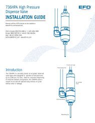
Pin Function<br />
1. Voltage initiate +, 5-24 VDC (35mA maximum)<br />
2. Voltage initiate -<br />
3. End-of-cycle feedback output +, 5-24 VDC (100mA maximum)<br />
4. End-of-cycle feedback output -<br />
5. 24 VDC supply + (100mA maximum)<br />
6. 24 VDC supply -<br />
7. Contact closure +, 24 VDC @ 20mA<br />
8. Contact closure -<br />
Note: An 8 pin male connector assembly is available.<br />
Specify #7017143.<br />
3<br />
7 6<br />
8 1<br />
5 4<br />
2<br />
Back panel I/O pin diagram
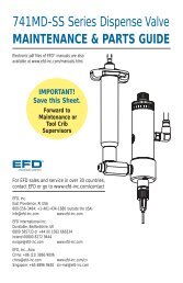
Item Part # Description<br />
11 7002004 Tubing - 6 mm OD urethane, blue*<br />
12 7017060 Air manifold 100 psi (6.9 bar)<br />
7017062 Air manifold 15 psi (1.03 bar)<br />
7017064 Air manifold 5 psi (0.34 bar)<br />
13 7017071 Face plate<br />
14 70170737 Rotary dial<br />
15 7017075 Chassis<br />
16 7017076 Cover<br />
17 7017078 Work panel - left<br />
18 7017080 Work panel - right<br />
19 7017082 Rubber strip - front<br />
10 7017084 Rubber strip - rear<br />
11 7017087 LCD protective lens<br />
12 7017088 Key pad<br />
13 7017090 Communication cable<br />
14 7017092 Circular foot pedal*<br />
15 7017094 Front cover<br />
4<br />
3<br />
20<br />
15<br />
11<br />
12 16<br />
Item Part # Description<br />
16 7017095 Display board assembly<br />
17 7017097 I/O board assembly<br />
18 7017101 Barrel holder sleeve<br />
19 7017104 Barrel holder<br />
20 7017133 Barrel h<strong>and</strong> grip<br />
21 7015199 Kit, 25w universal power supply*<br />
22 7023528 Screw – M3 x 6 mm, buttonhead<br />
23 7023533 Screw – M4 x 12 mm, buttonhead<br />
24 7023542 Screw – M4 x 8 mm, buttonhead<br />
25 7023572 Screw – M6 x 20 mm, buttonhead<br />
26 7023574 Screw – M6 x 25 mm, buttonhead<br />
27 7023577 M6 x 8 mm T-Slot nut<br />
28 7017128 Adapter hose holder<br />
7017157 Washer<br />
29 7022198 Fitting – 1/4-inch NPT x 6 mm*<br />
* Not shown<br />
22<br />
22<br />
13<br />
2<br />
17<br />
5<br />
7<br />
24<br />
23<br />
9<br />
6<br />
27<br />
10<br />
18<br />
23<br />
19<br />
25<br />
Schematic<br />
8<br />
28<br />
26<br />
23
24<br />
Troubleshoot<br />
If you encounter a problem that you cannot readily solve, call <strong>EFD</strong>.<br />
Trouble Possible cause <strong>and</strong> correction<br />
No power Be sure that there is power at the wall receptacle. Note: there is a resettable<br />
internal fuse on the Ultimus unit, so there is no need to ever replace the fuse.<br />
Allow unit to cool down, <strong>and</strong> it will reset itself as necessary.<br />
Auxiliary output Insure that the load does not exceed 100mA. If the output has been overloaded,<br />
is not functioning remove the load <strong>and</strong> allow circuit to cool. The circuit will reset itself.<br />
Inconsistent dots 1. Check dispensing tip, syringe barrel <strong>and</strong> material for possible clogging.<br />
2. Check dispenser air pressure display to be sure air pressure is not varying. If<br />
needed, use the filter regulator #7002002.<br />
3. Air bubbles in the material can cause inconsistency. For best results, remove<br />
all air bubbles.<br />
Timer seems Check to be sure you are not in STEADY mode. The upper left corner of the<br />
inoperative display should read TIMED or MEMORY.<br />
Note: The <strong>EFD</strong> timer is very reliable. Any failure will be total, so that no<br />
inconsistency is possible. Most questions regarding the timer are resolved by<br />
simply turning STEADY mode off.<br />
Material suck-back 1. Use a SmoothFlow piston or LV Barrier to prevent material being drawn into<br />
the dispenser.<br />
2. Another option is the order the vacuum suck-back filter trap accessory, which<br />
is guaranteed to prevent fluid for leaking into the dispenser. Order part<br />
#7017115.<br />
3. If suck-back occurs, attach an empty barrel, put in STEADY mode, place the<br />
barrel in a cup, then press the foot pedal to expel the fluid.<br />
4. If the problem cannot be corrected, contact an <strong>EFD</strong> Fluid Application<br />
Specialist for assistance.<br />
Dispensers can be returned to <strong>EFD</strong> for repair.<br />
Display backlight The Ultimus workstation is in sleep/power save mode. Press any button or press<br />
is off the foot pedal to reactivate.<br />
Voltage initiate Check to see that the voltage is between 5 <strong>and</strong> 24 VDC <strong>and</strong> the current does<br />
does not function not exceed 100mA.<br />
Air leaking from Air from the exhaust is normal when vacuum is used. If vacuum is completely<br />
exhaust port off <strong>and</strong> you still hear air, make sure plant air supply to your unit is set to within<br />
80 to 100 psi (5.5 to 6.9 bar).
Helpful Hints<br />
1. There are three core variables to the Ultimus dispensing workstation: time, pressure <strong>and</strong><br />
vacuum. Adjust just one of these at a time, in small increments, to achieve the correct deposit.<br />
2. Another variable is tip size. Choose the right tip for the deposit type. Remember, smaller tips<br />
require more pressure <strong>and</strong> more time. Try different tips without changing the time or pressure<br />
settings <strong>and</strong> observe the results.<br />
3. Tapered tips reduce the amount of air pressure needed to dispense thick materials. They also<br />
help prevent drooling at the end of a dispense cycle.<br />
4. To ensure smooth fluid flow <strong>and</strong> to make consistent deposits, keep the dispense tip at a 45°<br />
angle to the work surface.<br />
5. Use <strong>EFD</strong> SmoothFlow pistons to make barrel loading, dispensing <strong>and</strong> h<strong>and</strong>ling cleaner, safer <strong>and</strong><br />
more accurate. Caution: If you dispense watery fluids <strong>and</strong> choose not to use <strong>EFD</strong> pistons, do not<br />
increase vacuum pressure rapidly <strong>and</strong> do not tip the barrel. Vacuum may pull fluid into the<br />
adapter hose; or if the syringe barrel is tipped, fluid may flow back into the dispenser.<br />
6. Always use new <strong>EFD</strong> syringe barrels <strong>and</strong> tips. Carefully dispose of after use. This procedure<br />
ensures maximum cleanliness, prevents contamination <strong>and</strong> provides proper safety.<br />
7. Do not completely fill the syringe barrel. For most fluids, optimum fill is a maximum 2/3 of the<br />
barrel capacity. For cyanoacrylates or watery fluids, optimum fill is 1/2 of the barrel capacity.<br />
Suggestions on Settings<br />
1. To reduce air pressure, turn the knob counterclockwise until the display reads at a lower-thanneeded<br />
pressure setting. Then turn clockwise to increase pressure until you reach the correct<br />
setting.<br />
2. Avoid high pressure settings with very short time settings (example: 80 psi; 5.5 bar at less than<br />
0.01 seconds). The ideal setup matches air pressure <strong>and</strong> tip size to create a “workable” flow<br />
rate – no splashing, but not too slow either – with a time setting that is not extremely low.<br />
3. With any fluid, always give the air pressure time to do its job. Moderate time <strong>and</strong> pressure<br />
provides the best results since dispensing pressure remains at its peak for a longer period of<br />
time.<br />
4. Longer dispense time settings generally provide the highest accuracy. However, in the interest of<br />
cost-effective production, do not use excessively long dispense time settings. Experiment to find<br />
what works best for your application.<br />
Helpful Hints<br />
25
26<br />
Productivity<br />
Tools<br />
Choose from this list of optional productivity tools to maximize your Ultimus dispensing<br />
workstation.<br />
Flexible arm syringe barrel holder<br />
This flexible arm mounts to the work panels <strong>and</strong> can be adjusted to multiple heights<br />
<strong>and</strong> angles. Specify #7017105.<br />
Stiff arm barrel holder<br />
This stiff arm mounts to the work panels <strong>and</strong> securely holds the syringe barrel in a<br />
fixed position. Specify #7017113.<br />
Barrel h<strong>and</strong> grip with finger switch <strong>and</strong> light<br />
H<strong>and</strong> grip with innovative finger switch that is activated by a built-in touch sensor.<br />
Incorporates a high-beam penlight to illuminate the dispensing target area. Fits all<br />
sizes of syringe barrels from 3cc to 55cc. Specify #7017131.<br />
<strong>Workstation</strong> lamp<br />
Helpful work lamp is mounted on a flexible arm, can be adjusted to multiple positions<br />
<strong>and</strong> provides targeted lighting to help operators work with greater accuracy <strong>and</strong><br />
comfort. Specify #7017122.<br />
Safety shield<br />
Large, acrylic safety shield is mounted on a flexible arm <strong>and</strong> can be adjusted to<br />
multiple positions. Provides splash guard protection in areas where adhesives <strong>and</strong><br />
toxic fluids are used. Specify #7017119.<br />
Vacuum suck-back filter trap<br />
Unique design is guaranteed to prevent fluid from being sucked back into the dispenser<br />
<strong>and</strong> ensures error-free operation. Holds up to 30cc of fluid. Specify #7017115.
Production extension shelf<br />
H<strong>and</strong>y extension shelf allows you to stack dispensers vertically for multiple dispensing<br />
applications, maximizes limited bench space <strong>and</strong> provides a flat work surface for other tools.<br />
Specify #7017138.<br />
Magnifying lens<br />
1.7x magnification ensures more accurate deposit placement, improves repeatability <strong>and</strong><br />
reduces risk of operator strain. Specify #7017135.<br />
I/O connector assembly<br />
Allows easy connection to the Ultimus dispenser for external control. One end<br />
has an 8 pin male DIN connector; opposite end connects to external devices.<br />
Specify #7017143.<br />
Vacuum pickup pen system<br />
All-in-one vacuum generator <strong>and</strong> pen system for picking up <strong>and</strong> placing small parts.<br />
For use with any air-powered dispenser. Specify #7017167.<br />
Five-micron regulator<br />
Required for production areas where clean, dry filtered factory air is not available, or to<br />
stabilize plant air supply for more consistent deposits. Specify #7002002.<br />
For dispensing cyanoacrylates, order the regulator with a coalescing filter that removes<br />
liquid aerosols from the air supply. Specify #7016548.<br />
Cleanroom filter muffler<br />
Attaches to the Ultimus exhaust port <strong>and</strong> filters output air to meet Fed 209-B (0.5 micron<br />
particulates). Designed for use in cleanroom environments. Specify #7017049.<br />
Productivity<br />
Tools<br />
#7002002 #7016548<br />
27
<strong>EFD</strong> Ten Year No-Fault Warranty<br />
<strong>EFD</strong> dispensers are warranted to the original end user for 10 years from date of purchase.<br />
Within the period of this warranty, <strong>EFD</strong> will repair or replace free of charge any defective part,<br />
regardless of fault, on return of the part, or the complete dispenser, prepaid to the factory.<br />
In no event shall any liability or obligation of <strong>EFD</strong> arising from this warranty exceed the<br />
purchase price of the equipment. Before using, user shall determine the suitability of the<br />
product for his intended use, <strong>and</strong> user assumes all risk <strong>and</strong> liability whatsoever in connection<br />
therewith. This warranty is valid only when clean, dry, filtered air is used.<br />
<strong>EFD</strong> makes no warranty whatsoever of merchantability or fitness for a particular purpose.<br />
In no event shall <strong>EFD</strong> be liable for incidental or consequential damages.<br />
A NORDSON COMPANY<br />
For <strong>EFD</strong> sales <strong>and</strong> service in over 30 countries,<br />
contact <strong>EFD</strong> or go to www.efd-inc.com<br />
<strong>EFD</strong>, Inc.<br />
East Providence, RI USA<br />
USA & Canada: 800-556-3484; +1-401-431-7000<br />
info@efd-inc.com www.efd-inc.com<br />
<strong>EFD</strong> International Inc.<br />
Dunstable, Bedfordshire, UK<br />
0800 585733 or +44 (0) 1582 666334<br />
Irel<strong>and</strong> 00800 8272 9444<br />
europe@efd-inc.com www.efd-inc.com<br />
®<br />
<strong>EFD</strong>, Inc., Asia<br />
China: +86 (21) 3866 9006<br />
china@efd-inc.com www.efd-inc.com<br />
Singapore: +65 6796 9522 sin-mal@efd-inc.com<br />
The Wave Design is a trademark of <strong>Nordson</strong> Corporation.<br />
©2009 <strong>Nordson</strong> Corporation 2400-MAN-01 (7017042) v111309 Rev-02<br />
This equipment is regulated by the European Union under WEEE<br />
Directive (2002/96/EC). See www.efd-inc.com for information about<br />
how to properly dispose of this equipment.