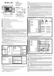
Operating Instructions DMP 48 AS / DMP 48 AW - Dold GmbH
Operating Instructions DMP 48 AS / DMP 48 AW - Dold GmbH
Operating Instructions DMP 48 AS / DMP 48 AW - Dold GmbH

Create successful ePaper yourself
Turn your PDF publications into a flip-book with our unique Google optimized e-Paper software.
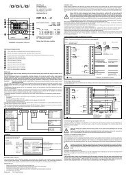
DOLD GMBH <strong>Operating</strong> instructions <strong>DMP</strong> <strong>48</strong> <strong>AS</strong> / <strong>AW</strong><br />
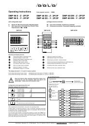
1.3 Please note during installation:<br />
External safety monitoring should be provided.<br />
Before connecting or starting up the <strong>DMP</strong> <strong>48</strong> <strong>AS</strong> / <strong>AW</strong> controller it is absolutely necessary to<br />
make sure that supply voltage corresponds to the nominal voltage given on the identification<br />
plate.<br />
Electrical connections must be made according to the accompanying connection diagram and<br />
the regulations of the local energy supply company must be observed.<br />
The unit must be protected from dampness (especially condensation) and heavy soiling in order<br />
to prevent malfunctioning.<br />
The <strong>DMP</strong> <strong>48</strong> <strong>AS</strong> / <strong>AW</strong> controller must be equipped with an RC network filter to reduce the effects<br />
of interference from the power supply network.<br />
An additional external filter must be switched into the controller’s power feed or other appropriate<br />
measures taken to prevent malfunction in the event of power supply faults.<br />
Sensor lines must be shielded. Unshielded sensor lines can lead to malfunctions.<br />
Controller and inductive loads, as well as sensor lines and load lines must be arranged in such a<br />
way that they cannot cause any interference to each other.<br />
Down-stream contractor relays must be equipped with RC suppressor circuits as per manufacturer’s<br />
instructions. Failure to use suppressor circuits could lead to the occurrence of short, high<br />
voltage peaks, which in turn can cause malfunctioning and excessive wear on contactors.<br />
The equalizing line must extend all the way to the controller supply terminals.<br />
Ambient temperature must lie within the range between 0...+50°C.<br />
All pre-set parameters must be checked during initial start-up and adapted to local conditions<br />
(systems)!<br />
1.4 Mechanical Data:<br />
Protection class: VDE 0631<br />
Insulation group: C as per DIN VDE 0110 b<br />
Type of protection: As per DIN VDE 0470 (replaces DIN 40 050)<br />
EN 60 529 / IEC 529<br />
Front panel: IP 50 (optionally: IP 54 with the proper mounting<br />
and a suitable sealing ring)<br />
Housing: IP 30<br />
IP 20<br />
Housing: Pull-out housing for mounting control panel with a B fastener as<br />
per DIN 43 835 (M 4 screw clamp)<br />
Material: PPO, glass-fiber reinforced (Noryl GFN2SE1)<br />
self-extinguishing, non-dripping<br />
fire protection class UL 94 V1<br />
Front panel dimensions: 96 x <strong>48</strong> mm DIN 43 700<br />
Control panel cutout: 92 +0.8 x 45 +0.6 mm<br />
Recess depth: approx. 125 mm including screwed plug connector<br />
Terminal connections: Screwed socket strips<br />
nominal cross section 2.5 mm 2<br />
Weight: approx. 420 g<br />
<strong>DMP</strong> <strong>48</strong> <strong>AS</strong> Version: 033 Number of pages: 5 of 25<br />
<strong>DMP</strong> <strong>48</strong> <strong>AW</strong> Edition: 08.08.2006 A0e033.doc