Operating Instructions DMP 48 AS / DMP 48 AW - Dold GmbH
Operating Instructions DMP 48 AS / DMP 48 AW - Dold GmbH
Operating Instructions DMP 48 AS / DMP 48 AW - Dold GmbH

You also want an ePaper? Increase the reach of your titles
YUMPU automatically turns print PDFs into web optimized ePapers that Google loves.
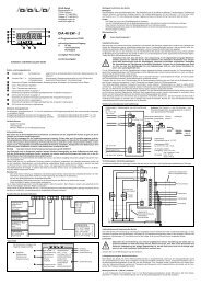
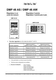
DOLD GMBH <strong>Operating</strong> instructions <strong>DMP</strong> <strong>48</strong> <strong>AS</strong> / <strong>AW</strong><br />
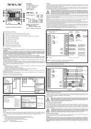
4. Outputs:<br />
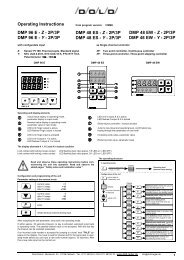
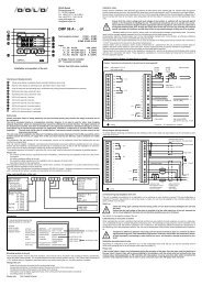
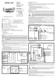
Outputs as per identification plate and accompanying terminal connection diagram:<br />
4.1 Potential-free relay contacts, make contact:<br />
Contact load: ≤ 250V AC, ≤ 8 A resistive load<br />
at 500 VA typically 10 6 switching cycles<br />
4.2 Logic output (optional):<br />
Logic outputs for activating solid-state relays,<br />
(in place of relay outputs K 1 or K 2):<br />
Open collector, not galvanically separated, short-circuit-proof,<br />
typically: 0/10 VDC, maximum: 20 mA.<br />
4.3 Analog output:<br />
Analog output as per order and identification plate<br />
Two-point controller: actual-value output (optional): range limits configurable<br />
Continuous-<br />
action controller: Control output: characteristic curve (heating or cooling) configurable<br />
Current output: output value configurable: 0...20 mA<br />
4...20 mA<br />
Voltage output: output value as per order: 0...1 VDC<br />
0...2 VDC<br />
0...5 VDC<br />
4.3.1 Technical data, analog output:<br />
Current and voltage output: resolution: 8 Bit<br />
Current output: load: ≤ 250 Ω<br />
Voltage output (short-circuit-proof): internal resistance Ri: ≤ 250 Ω<br />
Note: Any current output present but not needed must have a terminating resistor of ≤ 250 Ω<br />
or a bridge (terminals 5-6).<br />
4.4 Output responses in cases of error:<br />
Output response in cases of sensor error:<br />
• Relay or logic outputs: Outputs assume the state defined on the configuration<br />
level.<br />
• Analog output: (continuous-action controller, actual-value output):<br />
output U: 0...1VDC, 0...2VDC, 0...5VDC: output signal: 0 VDC<br />
<strong>DMP</strong> <strong>48</strong> <strong>AS</strong> Version: 033 Number of pages: 9 of 25<br />
<strong>DMP</strong> <strong>48</strong> <strong>AW</strong> Edition: 08.08.2006 A0e033.doc