Three-phase Synchronous motors - Baumüller Reparaturwerk
Three-phase Synchronous motors - Baumüller Reparaturwerk
Three-phase Synchronous motors - Baumüller Reparaturwerk

Create successful ePaper yourself
Turn your PDF publications into a flip-book with our unique Google optimized e-Paper software.
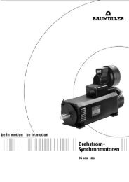
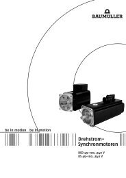
<strong>Three</strong>-<strong>phase</strong><br />
<strong>Synchronous</strong> <strong>motors</strong><br />
DSD 45-100..540 V<br />
DS 45-100..540 V
Table of contents<br />
<strong>Three</strong>-<strong>phase</strong> synchronous <strong>motors</strong> DS/DSD 45-100..540V<br />
<strong>Three</strong>-<strong>phase</strong> synchronous <strong>motors</strong> DSD 45 - 100..540V....................................................................................3<br />
General technical data ...........................................................................................................................................3<br />
Explanation of the motor data ................................................................................................................................4<br />
Type key .................................................................................................................................................................4<br />
Technical data ........................................................................................................................................................5<br />
DSD 045..64 U.. (IP 64 without fan).............................................................................................................5<br />
DSD 056..64 U.. (IP 64 without fan).............................................................................................................6<br />
DSD 056..54 O.. (IP 54 with fan)..................................................................................................................7<br />
DSD 071..64 U.. (IP 64 without fan).............................................................................................................8<br />
DSD 071..54 O.. (IP 54 with fan)..................................................................................................................9<br />
DSD 100..64 U.. (IP 64 without fan)...........................................................................................................10<br />
DSD 100..54 O.. (IP 54 with fan)................................................................................................................11<br />
Radial force diagrams ..........................................................................................................................................12<br />
Brake assignment.................................................................................................................................................15<br />
Encoders ..............................................................................................................................................................16<br />
Resolver .....................................................................................................................................................16<br />
SINCOS SRS/SRM 50 (Stegmann) ...........................................................................................................17<br />
Drawings...............................................................................................................................................................18<br />
DSD 45 standard version, main connection with connector .....................................................................18<br />
DSD 56 / 71 / 100 standard version, main connection with terminal box .................................................19<br />
DSD 56 / 71 / 100 standard version, main connection with connector.....................................................20<br />
DSD 56 / 71 / 100 standard version with fan, main connection with terminal box....................................21<br />
DSD 56 / 71 / 100 standard version with fan, main connection with connector .......................................22<br />
Motor cables .........................................................................................................................................................23<br />
Nominal voltage..........................................................................................................................................23<br />
Core lettering..............................................................................................................................................23<br />
Cable data ..................................................................................................................................................23<br />
Main connection cables / Assembled cable with connector.................................................................................25<br />
Encoder cables.....................................................................................................................................................26<br />
Commissioning and maintenance instructions.....................................................................................................27<br />
<strong>Three</strong>-<strong>phase</strong> synchronous <strong>motors</strong> DS 45 - 100..540V ....................................................................................29<br />
General technical data .........................................................................................................................................29<br />
Ratings definition ..................................................................................................................................................30<br />
Winding isolation and temperature rise................................................................................................................30<br />
Explanation of the motor data ..............................................................................................................................30<br />
Basic calculation...................................................................................................................................................30<br />
Performance overview..........................................................................................................................................31<br />
Type key ...............................................................................................................................................................31<br />
Technical data ......................................................................................................................................................32<br />
DS standard version...................................................................................................................................32<br />
Radial force diagrams ..........................................................................................................................................38<br />
DS in standard version or with fan .............................................................................................................39<br />
DS in short version.....................................................................................................................................42<br />
Main connection – terminal marking and connector assignment.........................................................................44<br />
Thermal sensor.....................................................................................................................................................45<br />
Fan data ...............................................................................................................................................................45<br />
Brake assignment.................................................................................................................................................46<br />
<strong>Three</strong>-<strong>phase</strong> synchronous <strong>motors</strong> 45 - 100 02/05 Technical alterations reserved<br />
<strong>Baumüller</strong> Nürnberg GmbH 1
<strong>Three</strong>-<strong>phase</strong> synchronous <strong>motors</strong> DS/DSD 45-100..540V<br />
Encoder ................................................................................................................................................................47<br />
Resolver .....................................................................................................................................................47<br />
SINCOS SRS/SRM 50 (Stegmann) ...........................................................................................................48<br />
DS 56 / 71 / 100 standard version, main connection with terminal box....................................................49<br />
DS 45 / 56 / 71 / 100 standard version, main connection with connector.................................................50<br />
DS 56 / 71 / 100 standard version with fan, main connection with terminal box ......................................51<br />
DS 56 / 71 / 100 standard version with fan, main connection with connector ..........................................52<br />
DS 56 / 71 / 100 short version, main connection with terminal box..........................................................53<br />
DS 56 / 71 / 100 short version, main connection with connector..............................................................54<br />
Main connection, fan and male and female encoder connectors ..............................................................55<br />
Motor cables .........................................................................................................................................................57<br />
Nominal voltage..........................................................................................................................................57<br />
Core lettering..............................................................................................................................................57<br />
Cable data ..................................................................................................................................................57<br />
Main connection cables / Assembled cable with connector.................................................................................59<br />
Encoder cables.....................................................................................................................................................60<br />
Commissioning and maintenance instructions.....................................................................................................61<br />
Note: Preliminary DSD list!<br />
The technical data—electrical and mechanical—are subject to change!<br />
Date: 05/03<br />
All information in this list represents nonbinding information for customers. The information is subject to<br />
continuous development and is continually being updated through our permanent updating service. Please note<br />
that data/numbers/information represent current values at the time of printing. This information is not legally<br />
binding for measurement, analysis and calculation. Before using any of the information listed in this bochure as<br />
the basis of personal calculations and/or applications, please ensure that the information you are using is<br />
current.<br />
No liability is assumed that the information presented here is correct<br />
Technical alterations reserved 02/05 <strong>Three</strong>-<strong>phase</strong> synchronous <strong>motors</strong> 45 - 100<br />
2 <strong>Baumüller</strong> Nürnberg GmbH
<strong>Three</strong>-<strong>phase</strong> synchronous <strong>motors</strong> DSD 45 - 100..540V<br />
New design for frame size<br />
56/71/100 available from<br />
October 2003.<br />
Frame size 45 is already<br />
available.<br />
General technical data<br />
<strong>Three</strong>-<strong>phase</strong> synchronous <strong>motors</strong> DSD 45-100..540V<br />
Version: IM B5 Horizontal mounting<br />
IM V1 Vertical mounting, shaft end to the bottom<br />
IM V3 Vertical mounting, shaft end to the top<br />
Protection type: IP65 Surface-cooled, without fan, DIN 40050, DIN 40053<br />
IP54 Surface-cooled, with fan<br />
Shaft gland: IP64 Standard<br />
Connection:<br />
IP65 with shaft sealing ring (option)<br />
Main connection U V W Terminal box<br />
Connector (option)<br />
Frame size 45 with connector as standard<br />
Control connection 12-pin connector<br />
Brake in the main connection<br />
Thermal sensor in control connection (for resolver only)<br />
Cooling type: IC 0041 Completely enclosed machine surface-cooled no fan<br />
IC 0641 as above, but with fan (air flow direction from B to A end)<br />
Thermal sensor: Linear thermal sensor for evaluation in the controller<br />
Temperature rise: ∆ϑ = 105K Insulation class F acc. to EN 60034<br />
Temperature range: 0....+ 40°C<br />
Storage: -30°C...+85°C<br />
Paint: black matt RAL 9005<br />
Bearing: ≥ 20,000h Service life<br />
Balance quality: N According to DIN ISO 2373<br />
R, S On request<br />
Vibration resistant up<br />
to:<br />
radial 3g 20 Hz to 2 kHz acc. to EN 60068-2-6<br />
axial 0.5g 20 Hz to 2 kHz acc. to EN 60068-2-6<br />
Higher vibration resistance on request<br />
Flange: acc. to IEC standard Dimension b1: Tolerance j6<br />
Shaft end: cylindrical Smooth acc. to DIN 748; (also available with key DIN 6885)<br />
Dimension d: Tolerance k6<br />
Centering with internal thread acc. to DIN 332 form D<br />
Holding brake: Option<br />
Actual speed encoder: 2-pin resolver<br />
Sincos encoder (option) Other encoders on request<br />
<strong>Three</strong>-<strong>phase</strong> synchronous <strong>motors</strong> 45 - 100 02/05 Technical alterations reserved<br />
<strong>Baumüller</strong> Nürnberg GmbH 3
<strong>Three</strong>-<strong>phase</strong> synchronous <strong>motors</strong> DSD 45-100..540V<br />
Explanation of the motor data<br />
M0, I0 Nominal torque (Nm) with<br />
nominal current (A) with speed >= 1 min -1 no time limit, I0 is the r.m.s. value<br />
M0, max, I0, max Maximum torque ( Nm ) with<br />
Maximum current (A) with zero speed, I0 max is the r.m.s. value<br />
PN Nominal power ( kW ) with nominal speed nN in continuous operation (S1)<br />
TA=40°C installation up to 1000m a.m.s.l.<br />
MN, IN Nominal torque (Nm) at<br />
nominal current (A) with nominal speed nN in continuous operation (S1); TA= 40°C<br />
nN Nominal speed ( min -1 )<br />
kTN Torque constant: MN / IN fN Nominal frequency (Hz)<br />
J Rotor inertia incl. resolver without holding brake (kg cm²)<br />
m Weight in kg<br />
The specified ratings / torques at nominal speed are achieved with a chopping frequency of ≥ 4 kHz in the power unit of the<br />
converter. A chopping frequency of > 6 kHz is recommended.<br />
Type key<br />
DSD G 100 S 64 U 20 -5<br />
DC link voltage: 5 540 V<br />
X special<br />
Nominal speed: e.g. 20 = 2000 min -1<br />
X: special<br />
Cooling: U Without fan<br />
O With fan<br />
W Water cooling<br />
Type of protection: e.g. 64 = IP64<br />
Length: S<br />
M<br />
L<br />
B<br />
Frame size: 045<br />
056<br />
071<br />
100<br />
Holding brake: Without<br />
with G<br />
Motor type: DSD <strong>Three</strong>-<strong>phase</strong><br />
<strong>Synchronous</strong><br />
Dynamic<br />
Technical alterations reserved 02/05 <strong>Three</strong>-<strong>phase</strong> synchronous <strong>motors</strong> 45 - 100<br />
4 <strong>Baumüller</strong> Nürnberg GmbH
Technical data<br />
DSD 045..64 U.. (IP 64 without fan)<br />
Mains voltage 3 AC 400 V for converters with uncontrolled supply<br />
Nom.<br />
speed<br />
Motor type Standstill<br />
torque 1)<br />
Standstill<br />
current 1)<br />
max.<br />
standstill<br />
torque<br />
<strong>Three</strong>-<strong>phase</strong> synchronous <strong>motors</strong> DSD 45-100..540V<br />
max.<br />
standstill<br />
current<br />
Nom.<br />
power 1)<br />
Nom.<br />
torque 1)<br />
nN MO MO IO MO,max MO,max IO,max PN PN MN MN IN<br />
min -1 Nm lbf ft A Nm lbf ft A kW hp Nm lbf ft A<br />
<strong>Three</strong>-<strong>phase</strong> synchronous <strong>motors</strong> 45 - 100 02/05 Technical alterations reserved<br />
<strong>Baumüller</strong> Nürnberg GmbH 5<br />
Nom.<br />
current 1)<br />
3000 DSD045S64U30-5 2.5 1.84 1.60 11 8 7.6 0.63 0.8 2.0 1.5 1.40<br />
DSD045M64U30-5 4.0 2.95 2.40 18 2) 13 12.0 0.94 1.3 3.0 2.2 2.0<br />
DSD045L64U30-5 5.2 3.84 3.10 25 2) 18 16.2 1.22 1.6 3.9 2.9 2.50<br />
4500 DSD045S64U45-5 2.5 1.84 2.25 11 8 11.0 0.89 1.2 1.9 1.4 1.95<br />
DSD045M64U45-5 4.0 2.95 3.45 18 2) 13 17.0 1.18 1.6 2.5 1.8 2.40<br />
DSD045L64U45-5 5.2 3.84 4.45 25 2) 18 23.0 1.37 1.8 2.9 2.1 2.74<br />
Nom.<br />
speed<br />
Motor type Torque<br />
constant<br />
Nom.<br />
frequency<br />
Rotor<br />
inertia<br />
(motor)<br />
Weight<br />
nN kTN kTN fN J J m m<br />
min -1 Nm/A lbf ft / A Hz Kgcm 2 lb in² kg lb<br />
3000 DSD045S64U30-5 1.43 1.05 200.0 1.39 0.47 4.2 9.3<br />
DSD045M64U30-5 1.50 1.11 200.0 1.64 0.56 5.3 11.7<br />
DSD045L64U30-5 1.56 1.15 200.0 1.90 0.65 6.3 13.9<br />
4500 DSD045S64U45-5 0.97 0.72 300.0 1.39 0.47 4.2 9.3<br />
DSD045M64U45-5 1.04 0.77 300.0 1.64 0.56 5.3 11.7<br />
DSD045L64U45-5 1.06 0.78 300.0 1.90 0.65 6.3 13.9<br />
1) Winding overheat ∆T < 105 K; direct flange connection (mounting plate 250mm×250mm)<br />
2) max. shaft torque: Mmax ≤ 16 Nm for shaft end with key<br />
Mmax ≤ 28 Nm for shaft end without key<br />
Legend<br />
American units
<strong>Three</strong>-<strong>phase</strong> synchronous <strong>motors</strong> DSD 45-100..540V<br />
DSD 056..64 U.. (IP 64 without fan)<br />
Mains voltage 3 AC 400 V for converters with uncontrolled supply<br />
Nom.<br />
speed<br />
Motor type Standstill<br />
torque 1)<br />
Standstill<br />
current 1)<br />
max.<br />
standstill<br />
torque<br />
max.<br />
standstill<br />
current<br />
Nom.<br />
power 1)<br />
Nom.<br />
torque 1)<br />
nN MO MO IO MO,max MO,max IO,max PN PN MN MN IN<br />
min -1 Nm lbf ft A Nm lbf ft A KW hp Nm lbf ft A<br />
2000 DSD056S64U20-5 5.5 4.06 2.4 23 17 11.0 1.0 1.3 4.8 3.5 2.2<br />
DSD056M64U20-5 8.8 6.49 3.8 38 28 18.0 1.6 2.1 7.5 5.5 3.3<br />
DSD056L64U20-5 11.5 8.48 4.9 52 38 24.0 2.0 2.7 9.4 6.9 4.2<br />
3000 DSD056S64U30-5 5.5 4.06 3.5 23 17 16.0 1.3 1.7 4.1 3.0 2.7<br />
DSD056M64U30-5 8.8 6.49 5.4 38 28 25.5 2.0 2.7 6.5 4.8 4.2<br />
DSD056L64U30-5 11.5 8.48 6.8 52 38 34.0 2.4 3.2 7.7 5.7 5.0<br />
4500 DSD056S64U45-5 5.5 4.06 4.9 23 17 22.0 1.6 2.1 3.4 2.5 3.3<br />
DSD056M64U45-5 8.8 6.49 7.6 38 28 36.0 2.4 3.2 5.0 3.7 4.7<br />
DSD056L64U45-5 11.5 8.48 9.6 52 38 47.5 2.3 3.1 4.8 3.5 4.7<br />
Nom.<br />
speed<br />
Motor type Torque<br />
constant<br />
Nom.<br />
frequency<br />
Rotor<br />
inertia<br />
(motor)<br />
Technical alterations reserved 02/05 <strong>Three</strong>-<strong>phase</strong> synchronous <strong>motors</strong> 45 - 100<br />
6 <strong>Baumüller</strong> Nürnberg GmbH<br />
Weight<br />
nN kTN kTN fN J J m m<br />
min -1 Nm/A lbf ft / A Hz Kgcm 2 lb in² Kg lb<br />
2000 DSD056S64U20-5 2.18 1.61 133.3 3.0 1.03 8.2 18.1<br />
DSD056M64U20-5 2.27 1.67 133.3 4.3 1.47 10.0 22.0<br />
DSD056L64U20-5 2.24 1.65 133.3 5.7 1.95 11.8 26.0<br />
3000 DSD056S64U30-5 1.52 1.12 200.0 3.0 1.03 8.2 18.1<br />
DSD056M64U30-5 1.55 1.14 200.0 4.3 1.47 10.0 22.0<br />
DSD056L64U30-5 1.54 1.14 200.0 5.7 1.95 11.8 26.0<br />
4500 DSD056S64U45-5 1.03 0.76 300.0 3.0 1.03 8.2 18.1<br />
DSD056M64U45-5 1.06 0.78 300.0 4.3 1.47 10.0 22.0<br />
DSD056L64U45-5 1.02 0.75 300.0 5.7 1.95 11.8 26.0<br />
1) Winding overheat ∆T < 105 K; direct flange connection (mounting plate 250mm×250mm)<br />
Legend<br />
American units<br />
Nom.<br />
current 1)
DSD 056..54 O.. (IP 54 with fan)<br />
Mains voltage 3 AC 400 V for converters with uncontrolled supply<br />
Nom.<br />
speed<br />
Motor type Standstill<br />
torque 1)<br />
Standstill<br />
current 1)<br />
max.<br />
standstill<br />
torque<br />
<strong>Three</strong>-<strong>phase</strong> synchronous <strong>motors</strong> DSD 45-100..540V<br />
Max.<br />
standstill<br />
current<br />
Nom.<br />
power 1)<br />
Nom.<br />
torque 1)<br />
nN MO MO IO MO,max MO,max IO,max PN PN MN MN IN<br />
min -1 Nm lbf ft A Nm lbf ft A KW hp Nm lbf ft A<br />
<strong>Three</strong>-<strong>phase</strong> synchronous <strong>motors</strong> 45 - 100 02/05 Technical alterations reserved<br />
<strong>Baumüller</strong> Nürnberg GmbH 7<br />
Nom.<br />
current 1)<br />
2000 DSD056S54O20-5 7.2 5.31 3.2 23 17 11.0 1.4 1.9 6.6 4.9 3.0<br />
DSD056M54O20-5 11.8 8.7 5.1 38 28 18.0 2.3 3.1 11.0 8.1 4.9<br />
DSD056L54O20-5 15.5 11.4 6.7 52 38 24.0 3.0 4.0 14.2 10.5 6.3<br />
3000 DSD056S54O30-5 7.2 5.31 4.6 23 17 16.0 2.0 2.7 6.3 4.6 4.1<br />
DSD056M54O30-5 11.8 8.7 7.3 38 28 25.5 3.3 4.4 10.4 7.7 6.6<br />
DSD056L54O30-5 15.5 11.4 9.4 52 38 34.0 4.1 5.5 13.0 9.6 8.2<br />
4500 DSD056S54O45-5 7.2 5.31 6.4 23 17 22.0 2.6 3.5 5.5 4.1 5.2<br />
DSD056M54O45-5 11.8 8.7 10.3 38 28 36.0 4.2 5.6 9.0 6.6 8.2<br />
DSD056L54O45-5 15.5 11.4 13.0 52 38 47.5 5.4 7.2 11.4 8.4 10.5<br />
Nom.<br />
speed<br />
Motor type Torque<br />
constant<br />
Nom.<br />
frequency<br />
Rotor<br />
inertia<br />
(motor)<br />
Weight<br />
nN kTN kTN fN J J m m<br />
min -1 Nm/A lbf ft / A Hz Kgcm 2 lb in² Kg lb<br />
2000 DSD056S54O20-5 2.20 1.62 133.3 3.0 1.03 11.0 24.3<br />
DSD056M54O20-5 2.24 1.65 133.3 4.3 1.47 12.8 28.2<br />
DSD056L54O20-5 2.25 1.66 133.3 5.7 1.95 14.6 32.2<br />
3000 DSD056S54O30-5 1.54 1.14 200.0 3.0 1.03 11.0 24.3<br />
DSD056M54O30-5 1.58 1.17 200.0 4.3 1.47 12.8 28.2<br />
DSD056L54O30-5 1.58 1.17 200.0 5.7 1.95 14.6 32.2<br />
4500 DSD056S54O45-5 1.06 0.78 300.0 3.0 1.03 11.0 24.3<br />
DSD056M54O45-5 1.10 0.81 300.0 4.3 1.47 12.8 28.2<br />
DSD056L54O45-5 1.09 0.80 300.0 5.7 1.95 14.6 32.2<br />
1) Winding overheat ∆T < 105 K; direct flange connection (mounting plate 250mm×250mm)<br />
Legend<br />
American units
<strong>Three</strong>-<strong>phase</strong> synchronous <strong>motors</strong> DSD 45-100..540V<br />
DSD 071..64 U.. (IP 64 without fan)<br />
Mains voltage 3 AC 400 V for converters with uncontrolled supply<br />
Nom.<br />
speed<br />
Motor type Standstill<br />
torque 1)<br />
Standstill<br />
current 1)<br />
Max.<br />
standstill<br />
torque<br />
max.<br />
standstill<br />
current<br />
Nom.<br />
power 1)<br />
Nom.<br />
torque 1)<br />
nN MO MO IO MO.max MO.max IO.max PN PN MN MN IN<br />
min -1 Nm lbf ft A Nm lbf ft A KW hp Nm lbf ft A<br />
Technical alterations reserved 02/05 <strong>Three</strong>-<strong>phase</strong> synchronous <strong>motors</strong> 45 - 100<br />
8 <strong>Baumüller</strong> Nürnberg GmbH<br />
Nom.<br />
current 1)<br />
2000 DSD071S64U20-5 13.5 9.96 5.7 51 38 24.5 2.3 3.1 11.0 8.1 4.9<br />
DSD071M64U20-5 19.5 14.4 8.4 75 55 36.5 3.1 4.2 15.0 11.1 6.8<br />
DSD071L64U20-5 25.0 18.4 10.7 100 74 48.0 4.2 5.6 20.0 14.8 8.9<br />
3000 DSD071S64U30-5 13.5 9.96 8.2 51 38 35.5 2.9 3.9 9.2 6.8 6.0<br />
DSD071M64U30-5 19.5 14.4 11.7 75 55 51.0 4.0 5.4 12.6 9.3 8.0<br />
DSD071L64U30-5 25.0 18.4 15.2 100 74 68.0 5.0 6.7 16.0 11.8 10.2<br />
4500 DSD071S64U45-5 13.5 9.96 11.6 51 38 50.0 3.4 4.6 7.2 5.3 6.7<br />
DSD071M64U45-5 19.5 14.4 17.0 75 55 75.0 4.3 5.8 9.2 6.8 8.7<br />
DSD071L64U45-5 25.0 18.4 21.4 100 74 95.0 5.2 7.0 11.0 8.1 10.0<br />
Nom.<br />
speed<br />
Motor type Torque<br />
constant<br />
Nom.<br />
frequency<br />
Rotor<br />
inertia<br />
(motor)<br />
Weight<br />
nN kTN kTN fN J J m m<br />
min -1 Nm/A lbf ft / A Hz kgcm 2 lb in² kg lb<br />
2000 DSD071S64U20-5 2.24 1.65 133.3 9.2 3.14 16.2 35.7<br />
DSD071M64U20-5 2.21 1.63 133.3 12.8 4.37 18.7 41.2<br />
DSD071L64U20-5 2.25 1.66 133.3 16.5 5.64 21.0 46.3<br />
3000 DSD071S64U30-5 1.53 1.13 200.0 9.2 3.14 16.2 35.7<br />
DSD071M64U30-5 1.58 1.17 200.0 12.8 4.37 18.7 41.2<br />
DSD071L64U30-5 1.57 1.16 200.0 16.5 5.64 21.0 46.3<br />
4500 DSD071S64U45-5 1.07 0.79 300.0 9.2 3.14 16.2 35.7<br />
DSD071M64U45-5 1.06 0.78 300.0 12.8 4.37 18.7 41.2<br />
DSD071L64U45-5 1.10 0.81 300.0 16.5 5.64 21.0 46.3<br />
1) Winding overheat ∆T < 105 K; direct flange connection (mounting plate 400mm×400mm)<br />
Legend<br />
American units
DSD 071..54 O.. (IP 54 with fan)<br />
Mains voltage 3 AC 400 V for converters with uncontrolled supply<br />
Nom.<br />
speed<br />
Motor type Standstill<br />
torque 1)<br />
Standstill<br />
current 1)<br />
Max.<br />
standstill<br />
torque<br />
<strong>Three</strong>-<strong>phase</strong> synchronous <strong>motors</strong> DSD 45-100..540V<br />
max.<br />
standstill<br />
current<br />
Nom.<br />
power 1)<br />
Nom.<br />
torque 1)<br />
nN MO MO IO MO,max MO,max IO,max PN PN MN MN IN<br />
min -1 Nm lbf ft A Nm lbf ft A kW hp Nm lbf ft A<br />
<strong>Three</strong>-<strong>phase</strong> synchronous <strong>motors</strong> 45 - 100 02/05 Technical alterations reserved<br />
<strong>Baumüller</strong> Nürnberg GmbH 9<br />
Nom.<br />
current 1)<br />
2000 DSD071S54O20-5 18.0 13.3 7.7 51 38 24.5 3.1 4.2 15.0 11.1 6.7<br />
DSD071M54O20-5 26.5 19.5 11.3 75 55 36.5 4.6 6.2 22.0 16.2 9.9<br />
DSD071L54O20-5 34.5 25.4 14.8 100 74 48.0 6.1 8.2 29.0 21.4 12.8<br />
3000 DSD071S54O30-5 18.0 13.3 11.2 51 38 35.5 4.2 5.6 13.5 10.0 8.8<br />
DSD071M54O30-5 26.5 19.5 15.9 75 55 51.0 6.3 8.4 20.0 14.8 12.6<br />
DSD071L54O30-5 34.5 25.4 21.0 100 74 68.0 8.0 10.7 24.5 18.1 15.4<br />
4500 DSD071S54O45-5 18.0 13.3 15.7 51 38 50.0 5.7 7.6 12.0 8.9 11.0<br />
DSD071M54O45-5 26.5 19.5 23.0 75 55 75.0 8.0 10.7 17.0 12.5 15.8<br />
DSD071L54O45-5 34.5 25.4 29.6 100 74 95.0 10.1 13.5 21.5 15.9 19.2<br />
Nom.<br />
speed<br />
Motor type Torque<br />
constant<br />
Nom.<br />
frequency<br />
Rotor<br />
inertia<br />
(motor)<br />
Weight<br />
nN kTN kTN fN J J m m<br />
min -1 Nm/A lbf ft / A Hz Kgcm 2 lb in² Kg lb<br />
2000 DSD071S54O20-5 2.24 1.65 133.3 9.2 3.14 20.0 44.1<br />
DSD071M54O20-5 2.22 1.64 133.3 12.8 4.37 22.5 49.6<br />
DSD071L54O20-5 2.26 1.67 133.3 16.5 5.64 24.8 54.7<br />
3000 DSD071S54O30-5 1.53 1.13 200.0 9.2 3.14 20.0 44.1<br />
DSD071M54O30-5 1.59 1.17 200.0 12.8 4.37 22.5 49.6<br />
DSD071L54O30-5 1.59 1.17 200.0 16.5 5.64 24.8 54.7<br />
4500 DSD071S54O45-5 1.09 0.80 300.0 9.2 3.14 20.0 44.1<br />
DSD071M54O45-5 1.08 0.80 300.0 12.8 4.37 22.5 49.6<br />
DSD071L54O45-5 1.12 0.83 300.0 16.5 5.64 24.8 54.7<br />
1) Winding overheat ∆T < 105 K; direct flange connection (mounting plate 400mm×400mm)<br />
Legend<br />
American units
<strong>Three</strong>-<strong>phase</strong> synchronous <strong>motors</strong> DSD 45-100..540V<br />
DSD 100..64 U.. (IP 64 without fan)<br />
Mains voltage 3 AC 400 V for converters with uncontrolled supply<br />
Nom.<br />
speed<br />
Motor type Standstill<br />
torque 1)<br />
Standstill<br />
current 1)<br />
max.<br />
standstill<br />
torque<br />
max.<br />
standstill<br />
current<br />
Nom.<br />
power 1)<br />
Nom.<br />
torque 1)<br />
nN MO MO IO MO,max MO,max IO,max PN PN MN MN IN<br />
min -1 Nm lbf ft A Nm lbf ft A KW hp Nm lbf ft A<br />
Technical alterations reserved 02/05 <strong>Three</strong>-<strong>phase</strong> synchronous <strong>motors</strong> 45 - 100<br />
10 <strong>Baumüller</strong> Nürnberg GmbH<br />
Nom.<br />
current 1)<br />
1200 DSD100S64U12-5 34.0 25.1 9.1 105 77 33 3.8 5.1 30.0 22.1 8.3<br />
DSD100M64U12-5 51.0 37.6 13.7 158 117 49 5.6 7.5 44.5 32.8 12.3<br />
DSD100L64U12-5 66.5 49 18.0 210 155 66 7.0 9.4 56.0 41.3 15.5<br />
2000 DSD100S64U20-5 34.0 25.1 14.5 105 77 52 5.4 7.2 26.0 19.2 11.5<br />
DSD100M64U20-5 51.0 37.6 21.0 158 117 75 7.7 10.3 37.0 27.3 16.0<br />
DSD100L64U20-5 66.5 49 27.5 210 155 102 9.4 12.6 45.0 33.2 19.5<br />
3000 DSD100S64U30-5 34.0 25.1 21.5 105 77 76 6.6 8.9 21.0 15.5 13.5<br />
DSD100M64U30-5 51.0 37.6 30.5 158 117 110 9.0 12.1 28.5 21.0 18.5<br />
DSD100L64U30-5 66.5 49 40.0 210 155 147 10.7 14.3 34.0 25.1 21.5<br />
4500 DSD100S64U45-5 34.0 25.1 30.5 105 77 110 5.9 7.9 12.5 9.2 11.7<br />
DSD100M64U45-5 51.0 37.6 44.0 158 117 157 7.5 10.1 16.0 11.8 15.0<br />
Nom.<br />
speed<br />
Motor type Torque<br />
constant<br />
Nom.<br />
frequency<br />
Rotor<br />
inertia<br />
(motor)<br />
Weight<br />
nN kTN kTN fN J J m m<br />
min -1 Nm/A lbf ft / A Hz Kgcm 2 lb in² kg lb<br />
1200 DSD100S64U12-5 3.61 2.66 80.0 42.5 14.52 31.0 68.3<br />
DSD100M64U12-5 3.62 2.67 80.0 60.0 20.50 38.5 84.9<br />
DSD100L64U12-5 3.61 2.66 80.0 77.0 26.31 45.5 100.3<br />
2000 DSD100S64U20-5 2.26 1.67 133.3 42.5 14.52 31.0 68.3<br />
DSD100M64U20-5 2.31 1.70 133.3 60.0 20.50 38.5 84.9<br />
DSD100L64U20-5 2.31 1.70 133.3 77.0 26.31 45.5 100.3<br />
3000 DSD100S64U30-5 1.56 1.15 200.0 42.5 14.52 31.0 68.3<br />
DSD100M64U30-5 1.54 1.14 200.0 60.0 20.50 38.5 84.9<br />
DSD100L64U30-5 1.58 1.17 200.0 77.0 26.31 45.5 100.3<br />
4500 DSD100S64U45-5 1.07 0.79 300.0 42.5 14.52 31.0 68.3<br />
DSD100M64U45-5 1.07 0.79 300.0 60.0 20.50 38.5 84.9<br />
Legend<br />
1) Winding overheat ∆T < 105 K; direct flange connection (mounting plate 400mm×400mm)<br />
American units
DSD 100..54 O.. (IP 54 with fan)<br />
Mains voltage 3 AC 400 V for converters with uncontrolled supply<br />
Nom.<br />
speed<br />
Motor type Standstill<br />
torque 1)<br />
Standstill<br />
current 1)<br />
Max.<br />
standstill<br />
torque<br />
<strong>Three</strong>-<strong>phase</strong> synchronous <strong>motors</strong> DSD 45-100..540V<br />
max.<br />
standstill<br />
current<br />
Nom.<br />
power 1)<br />
Nom.<br />
torque 1)<br />
nN MO MO IO MO,max MO,max IO,max PN PN MN MN IN<br />
min -1 Nm lbf ft A Nm lbf ft A KW hp Nm lbf ft A<br />
<strong>Three</strong>-<strong>phase</strong> synchronous <strong>motors</strong> 45 - 100 02/05 Technical alterations reserved<br />
<strong>Baumüller</strong> Nürnberg GmbH 11<br />
Nom.<br />
current 1)<br />
1200 DSD100S54O12-5 43.5 32.1 11.8 105 77 33 4.6 6.2 37.0 27.3 10.2<br />
DSD100M54O12-5 67.0 49.4 18.0 158 117 49 7.3 9.8 58.0 42.8 16.1<br />
DSD100L54O12-5 89.0 65.6 24.0 210 155 66 9.3 12.5 74.0 54.6 20.6<br />
2000 DSD100S54O20-5 43.5 32.1 18.5 105 77 52 6.8 9.1 32.5 24.0 14.3<br />
DSD100M54O20-5 67.0 49.4 27.5 158 117 75 10.3 13.8 49.0 36.1 21.2<br />
DSD100L54O20-5 89.0 65.6 37.0 210 155 102 13.4 18.0 64.0 47.2 27.7<br />
3000 DSD100S54O30-5 43.5 32.1 27.2 105 77 76 8.6 11.5 27.5 20.3 18.0<br />
DSD100M54O30-5 67.0 49.4 40.0 158 117 110 13.2 17.7 42.0 31.0 26.8<br />
DSD100L54O30-5 89.0 65.6 53.5 210 155 147 17.0 22.8 54.0 39.8 34.0<br />
4500 DSD100S54O45-5 43.5 32.1 39.0 105 77 110 10.0 13.4 21.5 15.9 20.0<br />
DSD100M54O45-5 67.0 49.4 57.5 158 117 157 15.0 20.1 32.0 23.6 29.5<br />
Nom.<br />
speed<br />
Motor type Torque<br />
constant<br />
Nom.<br />
frequency<br />
Rotor<br />
inertia<br />
(motor)<br />
Weight<br />
nN kTN kTN fN J J m m<br />
min -1 Nm/A lbf ft / A Hz Kgcm 2 lb in² kg lb<br />
1200 DSD100S54O12-5 3.63 2.68 80.0 42.5 14.52 36.3 80.0<br />
DSD100M54O12-5 3.60 2.66 80.0 60.0 20.50 43.8 96.6<br />
DSD100L54O12-5 3.59 2.65 80.0 77.0 26.31 50.8 112.0<br />
2000 DSD100S54O20-5 2.25 1.66 133.3 42.5 14.52 36.3 80.0<br />
DSD100M54O20-5 2.31 1.70 133.3 60.0 20.50 43.8 96.6<br />
DSD100L54O20-5 2.38 1.76 133.3 77.0 26.31 50.8 112.0<br />
3000 DSD100S54O30-5 1.53 1.13 200.0 42.5 14.52 36.3 80.0<br />
DSD100M54O30-5 1.56 1.15 200.0 60.0 20.50 43.8 96.6<br />
DSD100L54O30-5 1.59 1.17 200.0 77.0 26.31 50.8 112.0<br />
4500 DSD100S54O45-5 1.07 0.79 300.0 42.5 14.52 36.3 80.0<br />
DSD100M54O45-5 1.08 0,80 300.0 60.0 20,50 43.8 96,6<br />
Legend<br />
1) Winding overheat ∆T < 105 K; direct flange connection (mounting plate 400mm×400mm)<br />
American units
<strong>Three</strong>-<strong>phase</strong> synchronous <strong>motors</strong> DSD 45-100..540V<br />
Radial force diagrams<br />
Permissible radial forces FR at the shaft end<br />
All bearings are dimensioned for a service life of approx. 20,000 operating hours; the loads specified in the<br />
following must not be exceeded. The specified permissible radial forces FR are valid only for horizontal<br />
mounting of the motor without additional axial forces.<br />
Axial load of the motor shaft<br />
When mounting clutches, pulleys, etc. onto the motor shaft, axial forces must not occur! Therefore use the<br />
internal thread of the shaft end as assembly aid.<br />
Example<br />
Force acting on the end of the shaft end (for force acting on the middle of the shaft end Fr x 1.1)<br />
Bearing life 20,000 h; shaft end with keyway<br />
n [ 1/min ]<br />
10000<br />
9000<br />
8000<br />
7000<br />
6000<br />
5000<br />
4000<br />
3000<br />
2000<br />
1000<br />
0<br />
0<br />
0 500 1000 1500 2000 2500 3000 3500 4000 4500<br />
Fr [ N ]<br />
Explanation of the example<br />
Kugellager<br />
Kugellager / Ball bearing Welle / Shaft<br />
The radial force Fr of the application is used to determine the possible maximum speed of the bearing in the<br />
“Ball bearing” characteristic.<br />
Radial force 850 N => maximum speed 4250 min -1<br />
The maximum transmittable torque results from the “Shaft” characteristic.<br />
Radial force 850 N => maximum transmittable torque 185 Nm<br />
Technical alterations reserved 02/05 <strong>Three</strong>-<strong>phase</strong> synchronous <strong>motors</strong> 45 - 100<br />
12 <strong>Baumüller</strong> Nürnberg GmbH<br />
Welle<br />
250<br />
200<br />
150<br />
100<br />
50<br />
M [ Nm ]
n in [ 1/min ]<br />
n in [ 1/min ]<br />
10000<br />
9000<br />
8000<br />
7000<br />
6000<br />
5000<br />
4000<br />
3000<br />
2000<br />
1000<br />
8000<br />
7000<br />
6000<br />
5000<br />
4000<br />
3000<br />
2000<br />
1000<br />
<strong>Three</strong>-<strong>phase</strong> synchronous <strong>motors</strong> DSD 45-100..540V<br />
DSD 45<br />
0<br />
0<br />
0 100 200 300<br />
Fr in [ N ]<br />
400 500 600<br />
Kugellager / Ball bearing Welle mit Paßfedernut / Shaft with key<br />
DSD 56<br />
0<br />
0<br />
0 200 400 600 800 1000 1200 1400 1600 1800<br />
Fr in [ N ]<br />
Kugellager / Ball bearing Welle / Shaft<br />
<strong>Three</strong>-<strong>phase</strong> synchronous <strong>motors</strong> 45 - 100 02/05 Technical alterations reserved<br />
<strong>Baumüller</strong> Nürnberg GmbH 13<br />
110<br />
100<br />
90<br />
80<br />
70<br />
60<br />
50<br />
40<br />
30<br />
20<br />
10<br />
M in [ Nm ]<br />
20<br />
10<br />
M in [ Nm ]
<strong>Three</strong>-<strong>phase</strong> synchronous <strong>motors</strong> DSD 45-100..540V<br />
n in [ 1/min ]<br />
n in [ 1/min ]<br />
8000<br />
7000<br />
6000<br />
5000<br />
4000<br />
3000<br />
2000<br />
1000<br />
DSD 71<br />
0<br />
0<br />
0 200 400 600 800 1000 1200 1400 1600 1800 2000 2200 2400 2600<br />
Fr in [ N ]<br />
10000<br />
9000<br />
8000<br />
7000<br />
6000<br />
5000<br />
4000<br />
3000<br />
2000<br />
1000<br />
Kugellager / Ball bearing Rollenlager / Roller bearing Welle / Shaft<br />
DSD 100<br />
0<br />
0<br />
0 500 1000 1500 2000 2500<br />
Fr in [ N ]<br />
3000 3500 4000 4500 5000<br />
Kugellager / Ball bearing Rollenlager / Roller bearing Welle / Shaft<br />
Technical alterations reserved 02/05 <strong>Three</strong>-<strong>phase</strong> synchronous <strong>motors</strong> 45 - 100<br />
14 <strong>Baumüller</strong> Nürnberg GmbH<br />
180<br />
160<br />
140<br />
120<br />
100<br />
80<br />
60<br />
40<br />
20<br />
480<br />
440<br />
400<br />
360<br />
320<br />
280<br />
240<br />
200<br />
160<br />
120<br />
80<br />
40<br />
M in [ Nm ]<br />
M in [ Nm ]
Brake assignment<br />
<strong>Three</strong>-<strong>phase</strong> synchronous <strong>motors</strong> DSD 45-100..540V<br />
The <strong>motors</strong> are optionally equipped with a holding brake. The brake uses the normally-on principle, i.e. the brake engages<br />
with the operating voltage is switched off or fails. The brakes are supplied for a switching voltage of 24 VDC ± 10%.<br />
The <strong>motors</strong> are available with the following holding brakes:<br />
Motor type DSD 45 DSD 56 DSD 71 DSD 100<br />
minimum holding torque 6 15 35 80<br />
max. perm. friction work per<br />
braking operation [J]<br />
1000 2000 5000 15000<br />
Connection values 24 V = 24 V = 24 V = 24 V =<br />
(±10% smoothed) 19 W 22 W 35 W 52 W<br />
Inertia [kgcm 2 ] 0.3 0.8 3.5 8.6<br />
Maximum speed [min -1 ] 6000 6000 6000 4500<br />
Switching time On<br />
Brake released [ms]<br />
50 70 100 140<br />
Off [ms] 50 70 100 140<br />
Weight [kg] 1.0 2.0 3.5 8.2<br />
None of the brakes are fail-safe brakes so that the torque may be reduced by interference factors beyond control. In<br />
accordance with the case of application, observe the relevant accident prevention guidelines as well as the basic safety and<br />
health requirements of Appendix I of the Machinery Directive and the harmonized European Standards.<br />
In the event of emergency stop or voltage failure, approx. 2,500 braking operations can be carried out without causing the<br />
holding brake to overheat (Condition: maximum external inertia = motor inertia and n max. type-related).<br />
<strong>Three</strong>-<strong>phase</strong> synchronous <strong>motors</strong> 45 - 100 02/05 Technical alterations reserved<br />
<strong>Baumüller</strong> Nürnberg GmbH 15
<strong>Three</strong>-<strong>phase</strong> synchronous <strong>motors</strong> DSD 45-100..540V<br />
Encoders<br />
Resolver<br />
Pole pair number 1<br />
Ratio 0.5<br />
Frequency 5 kHz<br />
Nominal input voltage 4 V<br />
Active input power for no-load operation 112 mW<br />
Current consumption for no-load operation 40 mA<br />
Max. output voltage for no-load operation 2 V eff<br />
Voltage constant -<br />
Rotor resistance 44 Ω ± 10%<br />
Stator resistance 28 Ω ± 10%<br />
Rotor impedance for no-load operation 70 + j 74 Ω ± 15%<br />
Rotor impedance at short-circuit 62 + j 66 Ω ± 15%<br />
Stator impedance for no-load operation with min. coupling 108 + j 206 Ω ± 15%<br />
Stator impedance at short-circuit and maximum coupling 97 + j 183 Ω ± 15%<br />
Phase shift 8°<br />
Zero voltage 15 mV / °<br />
Phase error referred to zero position 10´<br />
Resolver connection<br />
View to contact side of female connector<br />
Pin Signal<br />
Technical alterations reserved 02/05 <strong>Three</strong>-<strong>phase</strong> synchronous <strong>motors</strong> 45 - 100<br />
16 <strong>Baumüller</strong> Nürnberg GmbH<br />
1<br />
2<br />
3<br />
4<br />
5<br />
6<br />
7<br />
8<br />
9<br />
10<br />
11<br />
12<br />
cos -<br />
sin –<br />
sin +<br />
TM -<br />
cos +<br />
TM +<br />
Ref +<br />
Ref -
SINCOS SRS/SRM 50 (Stegmann)<br />
<strong>Three</strong>-<strong>phase</strong> synchronous <strong>motors</strong> DSD 45-100..540V<br />
Number of sine, cosine periods per revolution<br />
SRS 50 / SRM 50<br />
1024<br />
Number of increments per revolution 32768<br />
Number of absolute resolved revolutions 1 4096<br />
Code type for the absolute value binary<br />
Output frequency of sine, cosine signals (kHz) 0 ... 200<br />
Error limits when evaluating 1024 signals, integral non-linearity<br />
(arc seconds)<br />
+/- 45<br />
Non-linearity within a sine, cosine period; differential nonlinearity<br />
(arc seconds)<br />
+/- 7<br />
Working speed up to which the absolute position can be<br />
formed (1/min)<br />
6000<br />
Maximum operating speed (1/min) 12000<br />
Output signals; 2 x 90° shifted sinusoidal signals (Vpp)<br />
1<br />
Output signal Serial RS 485,<br />
asynchronous,<br />
halbduplex<br />
Operating voltage range (V) 7 ... 12<br />
Operating current without load (mA) 80<br />
SRS/SRM 50 connection<br />
View to contact side of female connector<br />
Pin Signal<br />
<strong>Three</strong>-<strong>phase</strong> synchronous <strong>motors</strong> 45 - 100 02/05 Technical alterations reserved<br />
<strong>Baumüller</strong> Nürnberg GmbH 17<br />
1<br />
2<br />
3<br />
4<br />
5<br />
6<br />
7<br />
8<br />
9<br />
10<br />
11<br />
12<br />
ref cos<br />
+ 485<br />
-<br />
-<br />
sin<br />
ref sin<br />
- 485<br />
cos<br />
-<br />
Gnd<br />
-<br />
+ U
<strong>Three</strong>-<strong>phase</strong> synchronous <strong>motors</strong> DSD 45-100..540V<br />
Drawings<br />
DSD 45 standard version,<br />
main connection with connector<br />
k = motor with encoder<br />
k2 = motor with brake and encoder<br />
q1 = motor with encoder<br />
q2 = motor with brake and encoder<br />
i6 = Centring with internal thread acc. to DIN 332 form D<br />
1 = Encoder connector<br />
2 = Connector for main connection/brake (use only up to 44 A)<br />
• DC link voltage of 540 V <strong>motors</strong><br />
• Key: Motors are also available with key DIN 6885.<br />
• IP 65 type of protection is ensured with mounted connectors only.<br />
• Shaft gland protection type is IP64<br />
Type Flange Shaft Motor Brake<br />
a1 b1 c1 e1 f1 i2 s1 d t u g2 g g1 k m1 p1 q q1 y y1 y2 s2 s3 k2 q2<br />
45 S - 80 8 100 3 30 7 14 16 5 115 90 94 240 - 75 134 195 - 16 16 - - 300 260<br />
45 M 270 164 225 330 290<br />
45 L 300 194 255 360 320<br />
Version IM B5 Type of protection IP 65 Cooling method IC 0041<br />
Technical alterations reserved 02/05 <strong>Three</strong>-<strong>phase</strong> synchronous <strong>motors</strong> 45 - 100<br />
18 <strong>Baumüller</strong> Nürnberg GmbH
DSD 56 / 71 / 100 standard version,<br />
main connection with terminal box<br />
k = motor with encoder<br />
k2 = motor with brake and encoder<br />
q1 = motor with encoder<br />
q2 = motor with brake and encoder<br />
i6 = Centring with internal thread acc. to DIN 332 form D<br />
1 = Encoder connector<br />
• DC link voltage of 540 V <strong>motors</strong><br />
• Key: Motors are also available with key DIN 6885.<br />
• Brake: When a brake is mounted the dimensions remain unchanged.<br />
• IP 65 type of protection is ensured with mounted connectors only.<br />
• Shaft gland protection type is IP64<br />
<strong>Three</strong>-<strong>phase</strong> synchronous <strong>motors</strong> DSD 45-100..540V<br />
Type Flange Shaft Motor Brake<br />
a1 b1 c1 e1 f1 i2 s1 d t u g2 g g3 k m1 p q q1 s2 s3 y y1 y2 k2 q2<br />
56 S 120 110 9 130 3.5 50 9 24 27 8 150 115 90 291 28 103 183 261 M20 M16 85 66 33 376 346<br />
56 M 329 221 299 414 384<br />
56 L 367 259 337 452 422<br />
71 S 142 130 10 165 3.5 58 12 28 31 8 186 142 90 337 32 129 230 307 M25 M16 110 70 35 421 391<br />
71 M 377 270 347 461 431<br />
71 L 417 310 387 501 471<br />
100 S 190 180 12 215 4 80 14 38 41 10 250 190 90 408 38 174 288 378 M16 M40 150 135 37 528 498<br />
100 M 460 340 430 580 550<br />
100 L 512 392 482 632 602<br />
Version IM B5 Type of protection IP 65 Cooling method IC 0041<br />
<strong>Three</strong>-<strong>phase</strong> synchronous <strong>motors</strong> 45 - 100 02/05 Technical alterations reserved<br />
<strong>Baumüller</strong> Nürnberg GmbH 19
<strong>Three</strong>-<strong>phase</strong> synchronous <strong>motors</strong> DSD 45-100..540V<br />
DSD 56 / 71 / 100 standard version,<br />
main connection with connector<br />
k = motor with encoder<br />
k2 = motor with brake and encoder<br />
q1 = motor with encoder<br />
q2 = motor with brake and encoder<br />
i6 = Centring with internal thread acc. to DIN 332 form D<br />
1 = Encoder connector<br />
2 = Connector for main connection/brake (use only up to 44 A)<br />
• DC link voltage of 540 V <strong>motors</strong><br />
• Key: Motors are also available with key DIN 6885.<br />
• IP 65 type of protection is ensured with mounted connectors only.<br />
• Shaft gland protection type is IP64<br />
Type Flange Shaft Motor Brake<br />
a1 b1 c1 e1 f1 i2 s1 d t u g2 g g3 k m1 p1 q q1 y y1 y2 s2 s3 k2 q2<br />
56 S 120 110 9 130 3.5 50 9 24 27 8 150 115 90 291 28 123 183 261 - - - - - 376 346<br />
56 M 329 221 299 414 384<br />
56 L 367 259 337 452 422<br />
71 S 142 130 10 165 3.5 58 12 28 31 8 186 142 90 337 32 136 230 307 - - - - - 421 391<br />
71 M 377 270 347 461 431<br />
71 L 417 310 387 501 471<br />
100 S 190 180 12 215 4 80 14 38 41 10 250 190 90 408 38 160 288 378 - - - - - 528 498<br />
100 M 460 340 430 580 550<br />
100 L 512 392 482 632 602<br />
Version IM B5 Type of protection IP 65 Cooling method IC 0041<br />
Technical alterations reserved 02/05 <strong>Three</strong>-<strong>phase</strong> synchronous <strong>motors</strong> 45 - 100<br />
20 <strong>Baumüller</strong> Nürnberg GmbH
DSD 56 / 71 / 100 standard version with fan,<br />
main connection with terminal box<br />
k = motor with encoder<br />
k2 = motor with brake and encoder<br />
q1 = motor with encoder<br />
q2 = motor with brake and encoder<br />
i6 = Centring with internal thread acc. to DIN 332 form D<br />
1 = Fan connector<br />
2 = Encoder connector<br />
• DC link voltage of 540 V <strong>motors</strong><br />
• Key: Motors are also available with key DIN 6885.<br />
• IP 65 type of protection is ensured with mounted connectors only.<br />
• Shaft gland protection type is IP64<br />
<strong>Three</strong>-<strong>phase</strong> synchronous <strong>motors</strong> DSD 45-100..540V<br />
Type Flange Shaft Motor Brake<br />
a1 b1 c1 e1 f1 i2 s1 d t u g2 g k m1 p q q1 q3 y y1 y2 s2 s3 k2 q2<br />
56 S 120 110 9 130 3.5 50 9 24 27 8 185 140 426 28 103 183 261 124 85 66 33 M20 M16 511 346<br />
56 M 464 221 299 549 384<br />
56 L 502 259 337 587 422<br />
71 S 142 130 10 165 3.5 58 12 28 31 8 230 180 466 32 129 230 307 124 110 70 35 M25 M16 550 391<br />
71 M 506 270 347 590 431<br />
71 L 546 310 387 630 471<br />
100 S 190 180 12 215 4 80 14 38 41 10 275 215 537 38 174 288 378 124 150 135 37 M16 M40 657 498<br />
100 M 589 340 430 709 550<br />
100 L 641 392 482 761 602<br />
Version IM B5 Type of protection IP 54 Cooling method IC 0641<br />
<strong>Three</strong>-<strong>phase</strong> synchronous <strong>motors</strong> 45 - 100 02/05 Technical alterations reserved<br />
<strong>Baumüller</strong> Nürnberg GmbH 21
<strong>Three</strong>-<strong>phase</strong> synchronous <strong>motors</strong> DSD 45-100..540V<br />
DSD 56 / 71 / 100 standard version with fan,<br />
main connection with connector<br />
k = motor with encoder<br />
k2 = motor with brake and encoder<br />
q1 = motor with encoder<br />
q2 = motor with brake and encoder<br />
i6 = Centring with internal thread acc. to DIN 332 form D<br />
1 = Fan connector<br />
2 = Encoder connector<br />
3 = Connector for main connection/brake<br />
• DC link voltage of 540 V <strong>motors</strong><br />
• Key: Motors are also available without key<br />
• IP 65 type of protection is ensured with mounted connectors only.<br />
• Shaft gland protection type is IP64<br />
Type Flange Shaft Motor Brake<br />
a1 b1 c1 e1 f1 i2 s1 d t u g2 g k m1 p1 q q1 q3 y y1 y2 s2 s3 k2 q2<br />
56 S 120 110 9 130 3.5 50 9 24 27 8 180 134 426 28 123 183 261 124 - - - - - 511 346<br />
56 M 464 221 299 549 384<br />
56 L 502 259 337 587 422<br />
71 S 142 130 10 165 3.5 58 12 28 31 8 230 178 466 32 136 230 307 124 - - - - - 550 391<br />
71 M 506 270 347 590 431<br />
71 L 546 310 387 630 471<br />
100 S 190 180 12 215 4 80 14 38 41 10 284 224 537 38 160 288 378 124 - - - - - 657 498<br />
100 M 589 340 430 709 550<br />
100 L 641 392 482 761 602<br />
Version IM B5 Type of protection IP 54 Cooling method IC 0641<br />
Technical alterations reserved 02/05 <strong>Three</strong>-<strong>phase</strong> synchronous <strong>motors</strong> 45 - 100<br />
22 <strong>Baumüller</strong> Nürnberg GmbH
Motor cables<br />
<strong>Three</strong>-<strong>phase</strong> synchronous <strong>motors</strong> DSD 45-100..540V<br />
General<br />
The motor cables are highly flexible trailing cables with overall shielding. They comply with the regulations VDE,<br />
UL and CSA.<br />
The control cables are integrated as star-quads integriert. When the sincos encoder is used the brake triggering<br />
and the connection of the thermal sensor are brought out via the main connector.<br />
The cables are particularly suitable for the optimum use of cable racks thanks to their low cross-section, low<br />
weight and non-impeding surface. They can thus be efficiently used in trailing chains.<br />
The overall shielding with an optical coverage of more than 85% makes it an EMC uncritical cable.<br />
The connector size is designed in accordance with the motor's standstill current I0.<br />
Technical data<br />
Technical description<br />
• Sheath resistance against media such as coolants, machine and gearbox oils<br />
• Abrasion resistance because of a special surface in cable racks and trailing chains<br />
• High-flexible, trailing cable<br />
• Sheath surface not blocking, satin-finish<br />
• Shield made of tinned copper braid with optical coverage of ≥ 85 %<br />
• Core insulation made of TPE or polyester, sheath material PUR holgene-free<br />
• Cable FCF-free and silicone-free<br />
• Behavior in case of fire: fire-inhibiting, halogene-free<br />
• Cable color in RAL 1028, melon yellow<br />
• Labelling with <strong>Baumüller</strong> sign, VDE, UL and CSA sign<br />
• Minimum bending radius for flexible use 12 x D<br />
Nominal voltage<br />
Uo/U 600 / 1000 V (power cores)<br />
U 24 V DC (control cores)<br />
Core lettering<br />
Power cores U, VV, WWW<br />
Colored control cable pairs as star-quads in red, white, black, yellow<br />
Assignment of pairs red – black (brake),<br />
white – yellow (temperature)<br />
Cable data<br />
Cable cross-section Nominal<br />
current<br />
[A] 1)<br />
Cable diameter<br />
[mm]<br />
4×1.5 mm 2 4×0.75 mm 2 15 11.7 – 12.3<br />
4×2.5 mm 2 4×0.75 mm 2 21 12.7 – 14.6<br />
4×4 mm 2 4×0.75 mm 2 28 14.2 – 15.4<br />
4×6 mm 2 4×0.75 mm 2 36 16.6 – 17.9<br />
4×10 mm 2 4×0.75 mm 2 50 20.5 – 21.5<br />
4×16 mm 2 4×0.75 mm 2 66 23.0 – 25.8<br />
4×25 mm 2 2×(2×1.5 mm 2 ) 84 26.3 – 29.7<br />
4×35 mm 2 2×(2×1.5 mm 2 ) 104 30.8 – 32.5<br />
1) Current carrying capacity acc. to table 5 laying type C or E<br />
(VDE 0113 / EN 60 204 Part 1 issue 1997)<br />
Ambient temperature 40°C<br />
<strong>Three</strong>-<strong>phase</strong> synchronous <strong>motors</strong> 45 - 100 02/05 Technical alterations reserved<br />
<strong>Baumüller</strong> Nürnberg GmbH 23
<strong>Three</strong>-<strong>phase</strong> synchronous <strong>motors</strong> DSD 45-100..540V<br />
Cable – connector assignment<br />
Cable cross-sections nominal<br />
current<br />
[A]<br />
Male<br />
connector<br />
540 V<br />
Volume<br />
4×1.5 mm 2 4×0.75 mm 2 15 1<br />
4×2.5 mm 2 4×0.75 mm 2 21 1.5<br />
4×4 mm 2 4×0.75 mm 2 28 1.5<br />
4×6 mm 2 4×0.75 mm 2 36 1.5<br />
4×10 mm 2 4×0.75 mm 2 50 1.5<br />
The connectors must be designed with respect to the I0 motor current. For the laying of the cables, the current<br />
carrying capacity acc. to table 5 laying type C or E (VDE 0113 / EN 60 204 Part 1 issue 1997) and an ambient<br />
temperature of 40°C must be considered.<br />
Cables of 2.5 mm 2 can be laid up to 100 m without additional filters, when larger cross-sections used, up to 40<br />
m are permissible. The terminal voltage at the motor must be < 1kV. When longer cables are used, filters must<br />
be installed between converter and motor.<br />
Application notes<br />
Operating temperature<br />
The cables can be operated within a temperature range from –20°C to +80°C.<br />
Cable laying at the motor<br />
The cables must not touch the motor surface.<br />
Smallest permissible bending radii<br />
12 times outer cable diameter.<br />
Smaller bending radii are possible with reduced service life.<br />
Technical alterations reserved 02/05 <strong>Three</strong>-<strong>phase</strong> synchronous <strong>motors</strong> 45 - 100<br />
24 <strong>Baumüller</strong> Nürnberg GmbH
Main connection cables / Assembled cable with connector<br />
<strong>Three</strong>-<strong>phase</strong> synchronous <strong>motors</strong> DSD 45-100..540V<br />
Nominal current: 15 A Nominal current: 36 A<br />
Cable 4 x 1.5 mm² + 4x 0.75 mm² Cable 4 x 6 mm² + 4x 0.75 mm²<br />
with connector size 1 with connector size 1.5<br />
Length in m Article no. Length in m Article no.<br />
5 324781 5 326600<br />
7 324782 7 326601<br />
10 324783 10 326602<br />
15 324784 15 326603<br />
20 324785 20 326604<br />
25 324786 25 326605<br />
30 324787 30 326606<br />
35 324788 35 326607<br />
40 324789 40 326608<br />
50 324790<br />
75 324791<br />
100 324792<br />
Nominal current: 21 A Nominal current: 50 A<br />
Cable 4 x 2.5 mm² + 4x 0.75 mm² Cable 4 x 10 mm² + 4x 0.75 mm²<br />
with connector size 1.5 with connector size 1.5<br />
Length in m Article no. Length in m Article no.<br />
5 326577 5 326609<br />
7 326578 7 326610<br />
10 326579 10 326611<br />
15 326580 15 326612<br />
20 326581 20 326613<br />
25 326582 25 326614<br />
30 326583 30 326615<br />
35 326584 35 326616<br />
40 326585 40 326617<br />
50 326586<br />
75 326587<br />
100 326588<br />
Nominal current: 28 A<br />
Cable 4 x 4 mm² + 4x 0.75 mm²<br />
Connector<br />
Type<br />
Size 1 f. 4x1.5mm<br />
Article no.<br />
2<br />
with connector size 1.5 Size 1.5 f. 4x2.5mm<br />
261740<br />
2 o. 4mm 2 Length in m Article no. Size 1.5 f. 4x6mm<br />
326574<br />
2 o.10mm 2<br />
326569<br />
5 326589<br />
7 326591<br />
10 326592<br />
15 326593<br />
20 326594<br />
25 326596<br />
30 326597<br />
35 326598<br />
40 326599<br />
Larger cable cross-sections on request.<br />
Longer cables can also be used. The terminal voltage at the motor must be < 1kV. In this case, however, filters<br />
must be installed between converter and motor.<br />
<strong>Three</strong>-<strong>phase</strong> synchronous <strong>motors</strong> 45 - 100 02/05 Technical alterations reserved<br />
<strong>Baumüller</strong> Nürnberg GmbH 25
<strong>Three</strong>-<strong>phase</strong> synchronous <strong>motors</strong> DSD 45-100..540V<br />
Encoder cables<br />
General<br />
A fully preassembled encoder cable is used for all encoder systems. Motor connection is via a 12-pin round<br />
signal connector and converter connection via a 15-pin sub-D plug. The encoder cables are available as<br />
'trailing' and 'non-trailing' cables. The trailing cable is suitable for use in trailing chains, for example. As opposed<br />
to the 'non-trailing' cable, the cable sheath consists of tougher PUR for use in environments with acids and<br />
bases (coolants) instead of PVC. Up to a length of 10 m, the cables are available in 1 m sections (1 m, 2 m, 10<br />
m). From a cable length of 10 m, the sections come in 5 m intervals (10 m, 15 m, …).<br />
In the case of servo <strong>motors</strong>, the resolver encoder system links the temperature sensor with the converter via the<br />
encoder cable.<br />
Technical data<br />
1. Technical description – non-trailing<br />
• LiYCY, 5x (2x0.14mm²) + 2 x 0.5mm² copper lead, twisted pair<br />
• PVC sheath, grey<br />
• 1 st end: 12-pin signal circular connector with 12 female contacts<br />
• 2 nd end: 15-pin D-Sub connector with male contacts and locking screws 4-4OUNC<br />
• <strong>Baumüller</strong> labelling, black<br />
• Outer diameter 9.0 mm (+/-3mm)<br />
• Bending radius: r ≥ 60 mm (fixed installation), r ≥ 135 mm (flexible use)<br />
• Nominal voltage: 250VAC<br />
2. Technical description – trailing<br />
• Li12YC11Y, 5x (2x0.14mm²) + 2 x 0.5mm² copper lead, twisted pair<br />
• PU sheath, black<br />
• 1 st end: 12-pin signal circular connector with 12 female contacts<br />
• 2 nd end: 15-pin D-Sub connector with male contacts and locking screws 4-4OUNC<br />
• <strong>Baumüller</strong> labelling, white<br />
• Outer diameter 9.0 mm (+/-3mm)<br />
• Bending radius: r ≥ 70 mm (fixed installation), r ≥ 100 mm (flexible use)<br />
• Nominal voltage: 300VAC<br />
Technical alterations reserved 02/05 <strong>Three</strong>-<strong>phase</strong> synchronous <strong>motors</strong> 45 - 100<br />
26 <strong>Baumüller</strong> Nürnberg GmbH
Application notes<br />
<strong>Three</strong>-<strong>phase</strong> synchronous <strong>motors</strong> DSD 45-100..540V<br />
• Operating temperature<br />
trailing non-trailing<br />
Limit temperature at the surface at the surface<br />
no / few movements -40 °C to +80 °C - 30 °C to +80 °C<br />
continuous movements - 30 °C to +80 °C -5 °C to + 70 °C<br />
• Cable laying at the motor<br />
The cables must not touch the motor surface.<br />
Ordering data<br />
Encoder cables / preassembled cables with connector<br />
Encoder cable<br />
Non-trailing,assembled Trailing, assembled<br />
Cable 5 x (2x014mm 2 ) + 2 x 0.5 mm² with<br />
connector<br />
Cable 5 x (2x014mm 2 ) + 2 x 0.5 mm² with<br />
connector<br />
Length in m Article no. Length in m Article no.<br />
1 243601 3 246658<br />
2 211338 4 243379<br />
3 219333 5 239540<br />
4 231166 6 242954<br />
5 209879 8 239541<br />
6 220197 10 239542<br />
7 216455 15 239543<br />
8 220429 20 239544<br />
10 210052 25 239545<br />
15 215716 30 239546<br />
20 218568 35 239547<br />
25 218569 40 240520<br />
30 217094 45 240521<br />
35 216444 50 240522<br />
40 217095 55 244033<br />
45 217567 60 245484<br />
50 217568<br />
55 217569<br />
60 217570 Encoder<br />
Article no.<br />
connector<br />
70 232088 Encoder<br />
connector<br />
201833<br />
Commissioning and maintenance instructions<br />
Please contact us for our commissioning and maintenance instructions for motor commissioning.<br />
<strong>Three</strong>-<strong>phase</strong> synchronous <strong>motors</strong> 45 - 100 02/05 Technical alterations reserved<br />
<strong>Baumüller</strong> Nürnberg GmbH 27
<strong>Three</strong>-<strong>phase</strong> synchronous <strong>motors</strong> DSD 45-100..540V<br />
Technical alterations reserved 02/05 <strong>Three</strong>-<strong>phase</strong> synchronous <strong>motors</strong> 45 - 100<br />
28 <strong>Baumüller</strong> Nürnberg GmbH
<strong>Three</strong>-<strong>phase</strong> synchronous <strong>motors</strong> DS 45 - 100..540V<br />
General technical data<br />
<strong>Three</strong>-<strong>phase</strong> synchronous <strong>motors</strong> DS 45-100..540V<br />
Version: IM B5 Horizontal mounting<br />
IM V1 Vertical mounting, shaft end to the bottom<br />
IM V3 Vertical mounting, shaft end to the top<br />
Type of protection: IP65 Surface-cooled, without fan, DIN 40050, DIN 40053<br />
IP54 Surface-cooled, with fan<br />
Shaft gland: IP64 Standard<br />
Connection:<br />
IP65 with shaft sealing ring (option)<br />
Main connection U V W Terminal box<br />
Connector (option)<br />
Frame size 45 with connector as standard<br />
Control connection 12-pin connector<br />
Brake in the main connection<br />
Thermal sensor in control connection (for resolver only)<br />
Cooling method: IC 0041 completely enclosed machine surface-cooled no fan<br />
IC 0641 as above, but with fan (air flow direction from B to A end)<br />
Thermal sensor: Linear thermal sensor for evaluation in the controller<br />
Temperature rise: ∆ϑ = 105K Insulation class F acc. to EN 60034<br />
Temperature range: 0....+ 40°C<br />
Storage: -30°C...+85°C<br />
Paint: black matt RAL 9005<br />
Lager: ≥ 20,000h Service life<br />
Balance quality: N According to DIN ISO 2373<br />
R, S On request<br />
Vibration-resistant up<br />
to:<br />
radial 3g 20 Hz to 2 kHz acc. to EN 60068-2-6<br />
axial 0.5g 20 Hz to kHz acc to EN 60068-2-6<br />
Higher vibration resistance on request<br />
Flange: acc. to IEC standard Dimension b1: Tolerance j6<br />
Shaft end: cylindrical According to DIN 748 with shaft key DIN 6885;<br />
also available without keyway)<br />
Dimension d: Tolerance k6<br />
Centering with internal thread acc. to DIN 332 form D<br />
Holding brake: Option<br />
Actual speed encoder: 2-pin resolver<br />
Sincos encoder (option) Other encoders on request<br />
<strong>Three</strong>-<strong>phase</strong> synchronous <strong>motors</strong> 45 - 100 02/05 Technical alterations reserved<br />
<strong>Baumüller</strong> Nürnberg GmbH 29
<strong>Three</strong>-<strong>phase</strong> synchronous <strong>motors</strong> DS 45-100..540V<br />
Ratings definition<br />
The ratings (torques) listed in the table apply to continuous operation (S1) with nominal speed at a maximum ambient<br />
temperature of 40°C with the machine being installed below 1000m a.m.s.l.<br />
If <strong>motors</strong> are to be operated in an ambient temperature of more than 40 °C or altitudes above 1000 m a.m.s.l., the required<br />
list nominal power PL (list torque Mn) results from the product of the factors k1, k2 specified in the table and the required<br />
power P (torque M).<br />
Ambient<br />
temperature<br />
Correction<br />
factor k1 Altitude a.m.s.l.<br />
up to<br />
Correction<br />
factor k2 40 °C 45°C 50 °C 55°C 60°C<br />
1 1.06 1.13 1.22 1.34<br />
1.000<br />
m<br />
2.000<br />
m<br />
3.000<br />
m<br />
4.000<br />
m<br />
5.000<br />
m<br />
1 1.07 1.16 1.27 1.55<br />
Winding isolation and temperature rise<br />
For ambient temperatures above 40 °C and enclosed<br />
installation of <strong>motors</strong>, it is absolutely necessary to contact the<br />
manufacturer, because design changes may be necessary.<br />
If, with increasing site altitude above 1000 m, the ambient<br />
temperature decreases by approx. 10 °C per 1000 m increase<br />
in altitude, no power correction is necessary.<br />
All machines of this series are designed in insulation class F according to EN 60034 for a permissible winding temperature of<br />
105 K at a room temperature of up to 40 °C. The insulation is resistant against gases and vapours of combustible materials<br />
and it meets the requirements placed on a moisture-proof and tropical insulation.<br />
A special insulation that can be obtained for an extra charge is necessary if concentrated acid vapours and metallic powders<br />
occur, with a permanent relative air humidity of more than 80% and as protection against termite and mould fungus attacks.<br />
In the case of converters with a DC link voltage > 500 V, the cables between the converter and the motor must not be longer<br />
than 20 meters. For longer cables, additional measures (e.g. motor filters) must be provided. The maximum permissible<br />
terminal voltage is 1000 V.<br />
Explanation of the motor data<br />
M0, I0 Nominal torque (Nm) with<br />
nominal current (A) with speed >= 1 min -1 without time limit, I0 is the r.m.s. value<br />
MN, IN Nominal torque (Nm) with<br />
Nominal current (A) with nominal speed nN in continuous operation (S1);TA = 40 °C*<br />
MS3-40%, IS3-40% Torque and speed for intermittent operation S3-40% duty time, cycle of 10 minutes<br />
nN Nominal speed ( min -1 )<br />
kE Motor e.m.f. referred to 1000 min -1 (voltage constant)<br />
kT Torque constant: kT x I0 = M0 + MR (intrinsic moment)<br />
kD Torque loss referred to 1000 min -1 (eddy-current loss)<br />
MR Bearing friction including hysteresis torque<br />
m Weight in kg<br />
J Rotor inertia incl. resolver without holding brake (kg cm²)<br />
The specified ratings / torques at nominal speed are achieved with a chopping frequency of ≥ 4 kHz in the power unit of the<br />
converter. A chopping frequency of > 6 kHz is recommended.<br />
* A part of the loss in the motor is dissipated via the flange. The temperature at the flange must not exceed 65°C!<br />
Basic calculation<br />
Valid under the prerequisite that torque and speed are within the speed-torque characteristic.<br />
Motor current I for speed n and torque M<br />
M + M<br />
I =<br />
+ k<br />
kT<br />
R D ∗<br />
n/10<br />
3<br />
[ A]<br />
-<br />
Torque M for any speed and current I<br />
n<br />
M = I∗<br />
k<br />
T − ( MR<br />
+ kD<br />
∗<br />
10<br />
[ Nm]<br />
Technical alterations reserved 02/05 <strong>Three</strong>-<strong>phase</strong> synchronous <strong>motors</strong> 45 - 100<br />
30 <strong>Baumüller</strong> Nürnberg GmbH<br />
3<br />
)
Performance overview<br />
<strong>Three</strong>-<strong>phase</strong> synchronous <strong>motors</strong> DS 45-100..540V<br />
DS (<strong>Three</strong>-<strong>phase</strong> current synchronous Frame size Standstill torque<br />
Standard version without fan DS 45...100 0.8 - 57 Nm<br />
Standard version with fan DSO 56...100 4.8 - 84 Nm<br />
Short version without fan DS 56...100 1.9 – 24 Nm<br />
Standard version with holding brake DSG 45...100 0.8 – 57 Nm<br />
Standard version with holding brake and fan DSOG 56...DSOG 100 4.8 – 84 Nm<br />
Short version with brake DSG 56...DSG 100 1.9 – 24 Nm<br />
Type key<br />
DS O G 100 K 2 5<br />
DC link voltage: 5 540 V<br />
Nominal speed: 1: 1200 min -1<br />
2: 2000 min -1<br />
3: 3000 min -1<br />
4: 4000 min -1<br />
6: 6000 min -1<br />
Length: Standard Short<br />
K A<br />
S B<br />
M C<br />
L D<br />
Frame size: 45<br />
56<br />
71<br />
100<br />
Holding brake: without<br />
with G<br />
Fan: without<br />
with O<br />
Motor type: DS <strong>Three</strong>-<strong>phase</strong><br />
synchronous<br />
<strong>Three</strong>-<strong>phase</strong> synchronous <strong>motors</strong> 45 - 100 02/05 Technical alterations reserved<br />
<strong>Baumüller</strong> Nürnberg GmbH 31
<strong>Three</strong>-<strong>phase</strong> synchronous <strong>motors</strong> DS 45-100..540V<br />
Technical data<br />
DS standard version<br />
Legend<br />
Type n N<br />
( 1 / min)<br />
M0<br />
(Nm)<br />
M0<br />
(lbf ft)<br />
M N<br />
(Nm)<br />
MN<br />
(lbf ft)<br />
M S3-40%<br />
(Nm)<br />
M S3-40<br />
(lbf ft)<br />
Technical alterations reserved 02/05 <strong>Three</strong>-<strong>phase</strong> synchronous <strong>motors</strong> 45 - 100<br />
32 <strong>Baumüller</strong> Nürnberg GmbH<br />
I 0<br />
(A)<br />
I N<br />
(A)<br />
I S3-40%<br />
(A)<br />
DS 45 S 3000 0.8 0.6 0.8 0.6 1.0 0.74 0.7 0.7 0.8<br />
DS 45 S 4000 0.7 0.5 1.2 0.89 0.9 0.8 1.3<br />
DS 45 S 6000 0.6 0.4 1.0 0.74 1.4 1.1 1.7<br />
DS 45 M 3000 1.7 1.3 1.6 1.2 2.4 1.8 1.3 1.3 1.9<br />
DS 45 M 4000 1.5 1.1 2.3 1.7 1.8 1.6 2.4<br />
DS 45 M 6000 1.1 0.8 2.0 1.5 2.7 1.9 3.2<br />
DS 45 L 3000 3.2 2.4 2.9 2.1 4.4 3.2 2.5 2.3 3.4<br />
DS 45 L 4000 2.7 2.0 4.2 3.1 3.3 2.9 4.3<br />
DS 45 L 6000 2.0 1.5 3.8 2.8 4.9 3.3 6.0<br />
DS 56 S 2000 3.8 2.8 3.7 2.7 5.4 4.0 1.8 1.8 2.6<br />
DS 56 S 3000 3.6 2.7 5.4 4.0 2.5 2.4 3.6<br />
DS 56 S 4000 3.4 2.5 5.3 3.9 3.2 3.0 4.5<br />
DS 56 S 6000 2.6 1.9 4.7 3.5 5.1 3.8 6.6<br />
DS 56 M 2000 7.0 5.2 6.9 5.1 10.1 7.4 3.0 3.0 4.3<br />
DS 56 M 3000 6.4 4.7 9.8 7.2 4.2 4.0 6.0<br />
DS 56 M 4000 5.6 4.1 9.4 6.9 5.5 4.6 7.6<br />
DS 56 M 6000 2.9 2.1 7.9 5.8 8.0 3.8 9.4<br />
DS 56 L 2000 10.0 7.4 9.5 7.0 14.1 10.4 4.1 4.0 5.8<br />
DS 56 L 3000 8.4 6.2 13.6 10.0 5.9 5.1 8.1<br />
DS 56 L 4000 6.9 5.1 12.7 9.4 7.7 5.6 10.0<br />
DS 56 L 6000 0.6 0.4 9.8 7.2 11.1 1.5 11.5<br />
DS 71 K 2000 10.5 7.7 10.3 7.6 15.2 11.2 4.4 4.4 6.4<br />
DS 71 K 3000 9.5 7.0 14.8 10.9 6.3 5.9 9.0<br />
DS 71 K 4000 8.2 6.0 14.2 10.5 8.3 6.7 11.4<br />
DS 71 K 6000 3.8 2.8 11.8 8.7 11.9 5.0 13.9<br />
DS 71 S 2000 16.5 12.2 15.4 11.4 23.4 17.3 6.6 6.3 9.5<br />
DS 71 S 3000 13.4 9.9 22.4 16.5 9.6 8.1 13.3<br />
DS 71 S 4000 10.3 7.6 20.7 15.3 12.4 8.2 16.0<br />
DS 71 S 6000 0.0 0.0 16.4 12.1 18.6 0.0 20.1<br />
DS 71 M 2000 22.0 16.2 20.0 14.8 27.6 20.4 8.4 7.8 10.7<br />
DS 71 M 3000 16.3 12.0 28.3 20.9 12.3 9.5 16.2<br />
DS 71 M 4000 10.4 7.7 16.3 12.0 15.8 8.2 12.4<br />
DS 71 M 6000 0.0 0.0 18 13.3 24.8 0.0 13.8<br />
DS 100 K 1200 25.0 18.4 24.8 18.3 36.3 26.8 6.3 6.3 9.2<br />
DS 100 K 2000 23.3 17.2 35.9 26.5 10.0 9.5 14.4<br />
DS 100 K 3000 19.9 14.7 34.4 25.4 14.5 11.9 20.2<br />
DS 100 K 4000 14.7 10.8 31.7 23.4 19.1 11.9 24.7<br />
DS 100 K 6000 0.0 0.0 24.8 18.3 28.2 0.0 19.8<br />
DS 100 S 1200 36.0 26.6 34.7 25.6 51.6 38.1 8.8 8.6 12.6<br />
DS 100 S 2000 31.4 23.2 50.4 37.2 14.0 12.4 19.7<br />
DS 100 S 3000 24.6 18.1 47.0 34.7 20.3 14.4 26.9<br />
DS 100 S 4000 13.8 10.2 41.7 30.8 27.0 11.5 32.1<br />
DS 100 M 1200 46.0 33.9 43.7 32.2 66.0 48.7 11.0 10.5 15.8<br />
DS 100 M 2000 38.2 28.2 63.6 46.9 17.6 15.0 24.6<br />
DS 100 M 3000 27.1 20.0 58.0 42.8 25.9 16.0 33.2<br />
DS 100 L 1200 57.0 42.0 52.1 38.4 79.7 58.8 13.5 12.5 19.0<br />
DS 100 L 2000 44.2 32.6 76.0 56.1 21.4 17.1 28.9<br />
DS 100 L 3000 28.1 20.7 67.7 49.9 32.2 16.9 39.0<br />
American units
Type n N<br />
( 1 / min)<br />
kE<br />
( V / 1000<br />
1/min)<br />
k T<br />
( Nm / A)<br />
kT (lbf ft /<br />
A)<br />
<strong>Three</strong>-<strong>phase</strong> synchronous <strong>motors</strong> DS 45-100..540V<br />
k D<br />
( Nm / 1000<br />
<strong>Three</strong>-<strong>phase</strong> synchronous <strong>motors</strong> 45 - 100 02/05 Technical alterations reserved<br />
<strong>Baumüller</strong> Nürnberg GmbH 33<br />
1/min)<br />
M R<br />
(Nm)<br />
M R<br />
(lbf ft)<br />
m<br />
(kg)<br />
m<br />
(lb)<br />
J<br />
(kgcm 2 )<br />
J<br />
(lb in²)<br />
DS 45 S 3000 82.3 1.36 1.00 0.005 0.127 0.094 4.9 10.8 1.5 0.51<br />
DS 45 S 4000 61.8 1.02 0.75<br />
DS 45 S 6000 41.2 0.68 0.50<br />
DS 45 M 3000 82.3 1.36 1.00 0.010 0.131 0.097 5.9 13.0 2.1 0.72<br />
DS 45 M 4000 61.8 1.02 0.75<br />
DS 45 M 6000 41.2 0.68 0.50<br />
DS 45 L 3000 82.3 1.36 1.00 0.021 0.140 0.103 6.9 15.2 3.4 1.16<br />
DS 45 L 4000 61.8 1.02 0.75<br />
DS 45 L 6000 41.2 0.68 0.50<br />
DS 56 S 2000 133 2.2 1.62 0.030 0.154 0.114 6.6 14.6 5.7 1.95<br />
DS 56 S 3000 95.2 1.57 1.16<br />
DS 56 S 4000 74.6 1.23 0.91<br />
DS 56 S 6000 46.0 0.76 0.56<br />
DS 56 M 2000 145.4 2.41 1.78 0.062 0.180 0.133 8.5 18.7 10.2 3.49<br />
DS 56 M 3000 102 1.69 1.25<br />
DS 56 M 4000 78.8 1.3 0.96<br />
DS 56 M 6000 54.5 0.9 0.66<br />
DS 56 L 2000 150 2.48 1.83 0.094 0.208 0.153 10.8 23.8 15.7 5.36<br />
DS 56 L 3000 104.7 1.73 1.28<br />
DS 56 L 4000 80 1.33 0.98<br />
DS 56 L 6000 55.6 0.92 0.68<br />
DS 71 K 2000 147.5 2.44 1.80 0.082 0.230 0.170 12.2 26.9 22.4 7.65<br />
DS 71 K 3000 102.4 1.69 1.25<br />
DS 71 K 4000 79 1.3 0.96<br />
DS 71 K 6000 54.3 0.9 0.66<br />
DS 71 S 2000 152.8 2.53 1.87 0.139 0.280 0.207 16.3 35.9 36.3 12.40<br />
DS 71 S 3000 105.2 1.74 1.28<br />
DS 71 S 4000 81.5 1.35 1.00<br />
DS 71 S 6000 56 0.9 0.66<br />
DS 71 M 2000 161 2.66 1.96 0.202 0.334 0.246 20.5 45.2 50.2 17.15<br />
DS 71 M 3000 109.7 1.81 1.33<br />
DS 71 M 4000 85.3 1.41 1.04<br />
DS 71 M 6000 54.5 0.9 0.66<br />
DS 100 K 1200 243 4.02 2.96 0.195 0.400 0.295 26.1 57.5 74 25.29<br />
DS 100 K 2000 153.5 2.54 1.87<br />
DS 100 K 3000 106 1.75 1.29<br />
DS 100 K 4000 80.4 1.33 0.98<br />
DS 100 K 6000 54.8 0.9 0.66<br />
DS 100 S 1200 250 4.15 3.06 0.297 0.489 0.361 32.7 72.1 108 36.91<br />
DS 100 S 2000 158 2.61 1.93<br />
DS 100 S 3000 109 1.8 1.33<br />
DS 100 S 4000 81.7 1.35 1.00<br />
DS 100 M 1200 257 4.25 3.13 0.398 0.579 0.427 39.6 87.3 141 48.18<br />
DS 100 M 2000 159.3 2.64 1.95<br />
DS 100 M 3000 108.6 1.8 1.33<br />
DS 100 L 1200 257.5 4.26 3.14 0.500 0.668 0.493 48.8 107.6 175 59.80<br />
DS 100 L 2000 162.6 2.69 1.98<br />
DS 100 L 3000 108.4 1.79 1.32
<strong>Three</strong>-<strong>phase</strong> synchronous <strong>motors</strong> DS 45-100..540V<br />
DS standard version with fan<br />
Legend<br />
Type n N<br />
( 1 / min)<br />
M0<br />
(Nm)<br />
M 0<br />
(lbf ft)<br />
MN<br />
(Nm)<br />
M N<br />
(lbf ft)<br />
MS3-40%<br />
(Nm)<br />
M S3-40%<br />
(lbf ft)<br />
Technical alterations reserved 02/05 <strong>Three</strong>-<strong>phase</strong> synchronous <strong>motors</strong> 45 - 100<br />
34 <strong>Baumüller</strong> Nürnberg GmbH<br />
I0<br />
(A)<br />
I N<br />
(A)<br />
I S3-40%<br />
(A)<br />
DSO 56 S 2000 4.8 3.5 4.8 3.5 5.5 4.1 2.2 2.3 2.6<br />
DSO 56 S 3000 4.8 3.5 5.3 3.9 3.1 3.2 3.5<br />
DSO 56 S 4000 4.7 3.5 5.2 3.8 4.0 4.1 4.5<br />
DSO 56 S 6000 4.2 3.1 4.7 3.5 5.9 5.4 6.0<br />
DSO 56 M 2000 9.2 6.8 9.1 6.7 10.3 7.6 3.9 3.9 4.4<br />
DSO 56 M 3000 9.0 6.6 10.1 7.4 5.5 5.5 6.2<br />
DSO 56 M 4000 8.6 6.3 9.6 7.1 7.2 7.0 7.7<br />
DSO 56 M 6000 7.3 5.4 8.5 6.3 10.5 8.8 10.2<br />
DSO 56 L 2000 13.2 9.7 13.1 9.7 14.5 10.7 5.4 5.4 6.0<br />
DSO 56 L 3000 12.5 9.2 14.2 10.5 7.7 7.5 8.5<br />
DSO 56 L 4000 11.7 8.6 13.1 9.7 10.1 9.2 10.3<br />
DSO 56 L 6000 9.2 6.8 11.5 8.5 14.7 10.9 13.4<br />
DSO 71 K 2000 14.0 10.3 13.9 10.3 16.3 12.0 5.8 5.8 6.8<br />
DSO 71 K 3000 13.7 10.1 15.9 11.7 8.4 8.4 9.7<br />
DSO 71 K 4000 13.4 9.9 15.0 11.1 11.0 10.8 12.0<br />
DSO 71 K 6000 11.8 8.7 13.5 10.0 16.0 14.1 16.0<br />
DSO 71 S 2000 23.0 17.0 22.8 16.8 25.6 18.9 9.2 9.2 10.3<br />
DSO 71 S 3000 21.9 16.2 24.5 18.1 13.4 13.0 14.5<br />
DSO 71 S 4000 20.5 15.1 23.4 17.3 17.3 15.8 18.0<br />
DSO 71 S 6000 16.3 12.0 18.1 13.3 25.2 18.9 20.8<br />
DSO 71 M 2000 31.0 22.9 30.2 22.3 33.4 24.6 12.1 11.9 13.2<br />
DSO 71 M 3000 28.6 21.1 33.5 24.7 17.8 16.8 19.6<br />
DSO 71 M 4000 26.2 19.3 29.4 21.7 22.9 20.0 22.3<br />
DSO 71 M 6000 18.8 13.9 25.0 18.4 35.0 22.7 29.6<br />
DSO 100 K 1200 36.0 26.6 35.9 26.5 41.5 30.6 9.0 9.1 10.5<br />
DSO 100 K 2000 35.6 26.3 41.3 30.5 14.3 14.3 16.6<br />
DSO 100 K 3000 35.1 25.9 40.4 29.8 20.9 20.7 23.7<br />
DSO 100 K 4000 33.5 24.7 37.7 27.8 27.5 26.2 29.4<br />
DSO 100 K 6000 27.6 20.4 32.2 23.7 40.5 32.5 37.6<br />
DSO 100 S 1200 53.0 39.1 52.8 38.9 59.0 43.5 12.9 12.9 14.4<br />
DSO 100 S 2000 52.4 38.6 60.1 44.3 20.5 20.5 23.4<br />
DSO 100 S 3000 50.1 37.0 57.2 42.2 29.8 28.7 32.6<br />
DSO 100 S 4000 46.1 34.0 51.2 37.8 39.8 35.5 39.3<br />
DSO 100 M 1200 69.0 50.9 68.8 50.7 77.9 57.5 16.3 16.4 18.6<br />
DSO 100 M 2000 67.5 49.8 75.4 55.6 26.4 26.1 29.1<br />
DSO 100 M 3000 63.1 46.5 69.9 51.6 38.7 36.1 39.9<br />
DSO 100 L 1200 84.0 62.0 83.8 61.8 96.8 71.4 19.9 19.9 23.0<br />
DSO 100 L 2000 81.4 60.0 91.8 67.7 31.5 30.9 34.7<br />
DSO 100 L 3000 75.0 55.3 82.9 61.1 47.4 43.2 47.6<br />
American units
Typ n N<br />
( 1 / min)<br />
kE<br />
( V / 1000<br />
1/min)<br />
k T<br />
( Nm / A)<br />
kT (lbf ft /<br />
A)<br />
<strong>Three</strong>-<strong>phase</strong> synchronous <strong>motors</strong> DS 45-100..540V<br />
k D<br />
( Nm / 1000<br />
<strong>Three</strong>-<strong>phase</strong> synchronous <strong>motors</strong> 45 - 100 02/05 Technical alterations reserved<br />
<strong>Baumüller</strong> Nürnberg GmbH 35<br />
1/min)<br />
M R<br />
(Nm)<br />
M R<br />
(lbf ft)<br />
m<br />
(kg)<br />
m<br />
(lb)<br />
J<br />
(kgcm 2 )<br />
J<br />
(lb in²)<br />
DSO 56 S 2000 132.9 2.2 1.62 0.030 0.154 0.114 8.3 18.3 5.7 1.95<br />
DSO 56 S 3000 95.2 1.57 1.16<br />
DSO 56 S 4000 74.6 1.23 0.91<br />
DSO 56 S 6000 52.2 0.86 0.63<br />
DSO 56 M 2000 145.4 2.41 1.78 0.062 0.180 0.133 10.2 22.5 10.2 3.49<br />
DSO 56 M 3000 102.1 1.69 1.25<br />
DSO 56 M 4000 78.8 1.3 0.96<br />
DSO 56 M 6000 54.5 0.9 0.66<br />
DSO 56 L 2000 149.9 2.48 1.83 0.094 0.208 0.153 12.5 27.6 15.7 5.36<br />
DSO 56 L 3000 104.7 1.73 1.28<br />
DSO 56 L 4000 80.1 1.33 0.98<br />
DSO 56 L 6000 55.6 0.92 0.68<br />
DSO 71 K 2000 147.5 2.44 1.80 0.082 0.230 0.170 14.7 32.4 22.4 7.65<br />
DSO 71 K 3000 102.4 1.69 1.25<br />
DSO 71 K 4000 78.9 1.3 0.96<br />
DSO 71 K 6000 54.3 0.9 0.66<br />
DSO 71 S 2000 152.8 2.53 1.87 0.139 0.280 0.207 18.8 41.4 36.3 12.40<br />
DSO 71 S 3000 105.2 1.74 1.28<br />
DSO 71 S 4000 81.5 1.35 1.00<br />
DSO 71 S 6000 56 0.9 0.66<br />
DSO 71 M 2000 160.9 2.66 1.96 0.202 0.334 0.246 23.0 50.7 50.2 17.15<br />
DSO 71 M 3000 109.7 1.81 1.33<br />
DSO 71 M 4000 85.3 1.41 1.04<br />
DSO 71 M 6000 54.5 0.9 0.66<br />
DSO 100 K 1200 243.1 4.02 2.96 0.195 0.400 0.295 29.6 65.3 74 25.29<br />
DSO 100 K 2000 153.5 2.54 1.87<br />
DSO 100 K 3000 106 1.75 1.29<br />
DSO 100 K 4000 80.4 1.33 0.98<br />
DSO 100 K 6000 54.8 0.9 0.66<br />
DSO 100 S 1200 250.7 4.15 3.06 0.297 0.489 0.361 36.2 79.8 108 36.91<br />
DSO 100 S 2000 158 2.61 1.93<br />
DSO 100 S 3000 109 1.8 1.33<br />
DSO 100 S 4000 81.7 1.35 1.00<br />
DSO 100 M 1200 257.1 4.25 3.13 0.398 0.579 0.427 43.1 95.0 141 48.18<br />
DSO 100 M 2000 159.3 2.64 1.95<br />
DSO 100 M 3000 108.6 1.8 1.33<br />
DSO 100 L 1200 257.5 4.26 3.14 0.500 0.668 0.493 52.3 115.3 175 59.80<br />
DSO 100 L 2000 162.6 2.69 1.98<br />
DSO 100 L 3000 108.4 1.79 1.32
<strong>Three</strong>-<strong>phase</strong> synchronous <strong>motors</strong> DS 45-100..540V<br />
DS short version<br />
Legend<br />
Type n N<br />
( 1 / min)<br />
M0<br />
(Nm)<br />
M 0<br />
(lbf ft)<br />
MN<br />
(Nm)<br />
M N<br />
(lbf ft)<br />
MS3-40%<br />
(Nm)<br />
M S3-40%<br />
(lbf ft)<br />
Technical alterations reserved 02/05 <strong>Three</strong>-<strong>phase</strong> synchronous <strong>motors</strong> 45 - 100<br />
36 <strong>Baumüller</strong> Nürnberg GmbH<br />
I 0<br />
(A)<br />
I N<br />
(A)<br />
I S3-40%<br />
(A)<br />
DS 56 A 2000 1.9 1.4 1.8 1.3 2.7 2.0 1.0 0.9 1.4<br />
DS 56 A 3000 1.8 1.3 2.8 2.1 1.5 1.4 2.2<br />
DS 56 A 4000 1.8 1.3 2.7 2.0 2.0 2.0 2.9<br />
DS 56 A 6000 1.4 1.0 2.5 1.8 3.1 2.5 4.1<br />
DS 56 B 2000 3.7 2.7 3.6 2.7 5.4 4.0 1.7 1.7 2.5<br />
DS 56 B 3000 3.6 2.7 5.3 3.9 2.4 2.4 3.5<br />
DS 56 B 4000 3.3 2.4 5.1 3.8 3.1 2.9 4.4<br />
DS 56 B 6000 2.4 1.8 4.6 3.4 4.6 3.3 5.8<br />
DS 71 B 2000 7.0 5.2 6.9 5.1 10.2 7.5 3.5 3.5 5.1<br />
DS 71 B 3000 6.5 4.8 10.0 7.4 5.3 5.1 7.6<br />
DS 71 B 4000 5.7 4.2 9.6 7.1 7.1 6.1 9.9<br />
DS 71 B 6000 3.3 2.4 8.2 6.0 10.8 5.9 13.1<br />
DS 71 C 2000 10.0 7.4 9.8 7.2 14.6 10.8 4.2 4.2 6.1<br />
DS 71 C 3000 8.9 6.6 14.2 10.5 6.1 5.5 8.7<br />
DS 71 C 4000 7.4 5.5 13.4 9.9 7.9 6.2 10.8<br />
DS 71 C 6000 2.2 1.6 10.8 8.0 11.6 3.4 13.0<br />
DS 100 B 1200 12.5 9.2 12.4 9.1 18.8 13.9 3.7 3.7 5.6<br />
DS 100 B 2000 12.3 9.1 18.8 13.9 6.3 6.3 9.5<br />
DS 100 B 3000 11.5 8.5 18.4 13.6 9.5 9.0 14.0<br />
DS 100 B 4000 9.8 7.2 17.5 12.9 12.8 10.5 18.0<br />
DS 100 B 6000 3.7 2.7 14.3 10.5 19.5 7.4 22.9<br />
DS 100 C 1200 18.5 13.6 18.4 13.6 27.2 20.1 5.5 5.5 8.1<br />
DS 100 C 2000 17.8 13.1 27.1 20.0 9.2 9.0 13.6<br />
DS 100 C 3000 15.5 11.4 26.1 19.3 13.9 12.1 19.8<br />
DS 100 C 4000 12.1 8.9 24.3 17.9 18.7 13.0 24.9<br />
DS 100 C 6000 0.0 0.0 20.1 14.8 28.0 0.0 31.0<br />
DS 100 D 1200 24.0 17.7 23.8 17.6 35.2 26.0 6.0 6.1 8.9<br />
DS 100 D 2000 22.3 16.4 34.7 25.6 9.6 9.1 14.0<br />
DS 100 D 3000 18.6 13.7 33.0 24.3 14.0 11.2 19.5<br />
DS 100 D 4000 13.0 9.6 30.1 22.2 18.5 10.8 23.7<br />
DS 100 D 6000 0.0 0.0 22.8 16.8 18.5 0.0 18.5<br />
American units
Typ n N<br />
( 1 / min)<br />
kE<br />
( V / 1000<br />
1/min)<br />
k T<br />
( Nm / A)<br />
k T<br />
(lbf ft /<br />
A)<br />
<strong>Three</strong>-<strong>phase</strong> synchronous <strong>motors</strong> DS 45-100..540V<br />
kD<br />
(lbf ft / A)<br />
MR<br />
(Nm)<br />
M R<br />
(lbf ft)<br />
<strong>Three</strong>-<strong>phase</strong> synchronous <strong>motors</strong> 45 - 100 02/05 Technical alterations reserved<br />
<strong>Baumüller</strong> Nürnberg GmbH 37<br />
m<br />
(kg)<br />
m<br />
(lb)<br />
J<br />
(kgcm 2 )<br />
J<br />
(lb in²)<br />
DS 56 A 2000 123.5 2.04 1.50 0.014 0.14 0.103 5.5 12.1 3.0 1.03<br />
DS 56 A 3000 82.3 1.36 1.00<br />
DS 56 A 4000 61.8 1.02 0.75<br />
DS 56 A 6000 41.2 0.68 0.50<br />
DS 56 B 2000 132.9 2.2 1.62 0.030 0.154 0.114 6.7 14.8 5.5 1.88<br />
DS 56 B 3000 95.2 1.57 1.16<br />
DS 56 B 4000 74.6 1.23 0.91<br />
DS 56 B 6000 52.2 0.86 0.63<br />
DS 71 B 2000 123.5 2.04 1.50 0.054 0.206 0.152 10.3 22.7 14.6 4.99<br />
DS 71 B 3000 82.3 1.36 1.00<br />
DS 71 B 4000 61.8 1.02 0.75<br />
DS 71 B 6000 41.2 0.68 0.50<br />
DS 71 C 2000 147.5 2.44 1.80 0.082 0.230 0.170 12.4 27.3 21.5 7.35<br />
DS 71 C 3000 102.4 1.69 1.25<br />
DS 71 C 4000 78.9 1.3 0.96<br />
DS 71 C 6000 54.3 0.9 0.66<br />
DS 100 B 1200 205.8 3.4 2.51 0.094 0.31 0.229 18.9 41.7 36.5 12.47<br />
DS 100 B 2000 123.5 2.04 1.50<br />
DS 100 B 3000 82.3 1.36 1.00<br />
DS 100 B 4000 61.7 1.02 0.75<br />
DS 100 B 6000 41.2 0.68 0.50<br />
DS 100 C 1200 205.8 3.4 2.51 0.144 0.355 0.262 22.5 49.6 53.3 18.21<br />
DS 100 C 2000 123.5 2.04 1.50<br />
DS 100 C 3000 82.3 1.36 1.00<br />
DS 100 C 4000 61.8 1.02 0.75<br />
DS 100 C 6000 41.0 0.68 0.50<br />
DS 100 D 1200 243.1 4.02 2.96 0.195 0.400 0.295 26.3 58.0 70.0 23.92<br />
DS 100 D 2000 153.5 2.54 1.87<br />
DS 100 D 3000 106 1.75 1.29<br />
DS 100 D 4000 80.4 1.33 0.98<br />
DS 100 D 6000 54.8 0.9 0.66
<strong>Three</strong>-<strong>phase</strong> synchronous <strong>motors</strong> DS 45-100..540V<br />
Radial force diagrams<br />
Permissible radial forces FR at the shaft end<br />
All bearings are dimensioned for a service life of approx. 20.000 operating hours; the loads specified in the<br />
following must not be exceeded. The specified permissible radial forces FR are valid only for horizontal<br />
mounting of the motor without additional axial forces.<br />
Axial load of the motor shaft<br />
When mounting clutches. pulleys. etc. onto the motor shaft. axial forces must not occur! Therefore use the<br />
internal thread of the shaft end as assembly aid.<br />
Example<br />
Force acting on the end of the shaft end (for force acting on the middle of the shaft end Fr x 1.1)<br />
Bearing life 20.000 h; shaft end with keyway<br />
n [ 1/min ]<br />
10000<br />
9000<br />
8000<br />
7000<br />
6000<br />
5000<br />
4000<br />
3000<br />
2000<br />
1000<br />
0<br />
0<br />
0 500 1000 1500 2000 2500 3000 3500 4000 4500<br />
Fr [ N ]<br />
Explanation of the example<br />
Kugellager<br />
Kugellager / Ball bearing Welle / Shaft<br />
The radial force Fr of the application is used to determine the possible maximum speed of the bearing in the<br />
“Ball bearing” characteristic.<br />
Radial force 850 N => maximum speed 4250 min -1<br />
The maximum transmittable torque results from the “Shaft” characteristic.<br />
Radial force 850 N => maximum transmittable torque 185 Nm<br />
Technical alterations reserved 02/05 <strong>Three</strong>-<strong>phase</strong> synchronous <strong>motors</strong> 45 - 100<br />
38 <strong>Baumüller</strong> Nürnberg GmbH<br />
Welle<br />
250<br />
200<br />
150<br />
100<br />
50<br />
M [ Nm ]
DS in standard version or with fan<br />
n [ 1/min ]<br />
n [ 1/min ]<br />
10500<br />
9000<br />
7500<br />
6000<br />
4500<br />
3000<br />
1500<br />
9000<br />
8000<br />
7000<br />
6000<br />
5000<br />
4000<br />
3000<br />
2000<br />
1000<br />
DS 36<br />
<strong>Three</strong>-<strong>phase</strong> synchronous <strong>motors</strong> DS 45-100..540V<br />
0<br />
0<br />
0 50 100 150 200 250 300 350 400 450<br />
Fr [ N ]<br />
Kugellager / Ball bearing Welle / Shaft<br />
DS 45<br />
0<br />
0<br />
0 100 200 300 400 500<br />
Fr [ N ]<br />
600 700 800 900 1000<br />
Kugellager / Ball bearing Welle / Shaft<br />
<strong>Three</strong>-<strong>phase</strong> synchronous <strong>motors</strong> 45 - 100 02/05 Technical alterations reserved<br />
<strong>Baumüller</strong> Nürnberg GmbH 39<br />
8<br />
6<br />
4<br />
2<br />
7<br />
6<br />
5<br />
4<br />
3<br />
2<br />
1<br />
18<br />
16<br />
14<br />
12<br />
10<br />
M [ Nm ]<br />
M [ Nm ]
<strong>Three</strong>-<strong>phase</strong> synchronous <strong>motors</strong> DS 45-100..540V<br />
n [ 1 /min ]<br />
n [ 1/min ]<br />
9000<br />
8000<br />
7000<br />
6000<br />
5000<br />
4000<br />
3000<br />
2000<br />
1000<br />
DS 56<br />
0<br />
0<br />
0 100 200 300 400 500<br />
Fr [ N ]<br />
600 700 800 900 1000<br />
8000<br />
7000<br />
6000<br />
5000<br />
4000<br />
3000<br />
2000<br />
1000<br />
Kugellager / Ball bearing Welle / Shaft<br />
DS 71<br />
0<br />
0<br />
0 200 400 600 800 1000 1200 1400 1600 1800<br />
Fr [ N ]<br />
Kugellager / Ball bearing Welle / Shaft<br />
Technical alterations reserved 02/05 <strong>Three</strong>-<strong>phase</strong> synchronous <strong>motors</strong> 45 - 100<br />
40 <strong>Baumüller</strong> Nürnberg GmbH<br />
45<br />
40<br />
35<br />
30<br />
25<br />
20<br />
15<br />
10<br />
5<br />
100<br />
87,5<br />
75<br />
62,5<br />
50<br />
37,5<br />
25<br />
12,5<br />
M [ Nm ]<br />
M [ Nm ]
n [ 1/min ]<br />
10000<br />
9000<br />
8000<br />
7000<br />
6000<br />
5000<br />
4000<br />
3000<br />
2000<br />
1000<br />
DS 100<br />
<strong>Three</strong>-<strong>phase</strong> synchronous <strong>motors</strong> DS 45-100..540V<br />
0<br />
0<br />
0 500 1000 1500 2000 2500 3000 3500 4000 4500<br />
Fr [ N ]<br />
Kugellager / Ball bearing Welle / Shaft<br />
<strong>Three</strong>-<strong>phase</strong> synchronous <strong>motors</strong> 45 - 100 02/05 Technical alterations reserved<br />
<strong>Baumüller</strong> Nürnberg GmbH 41<br />
250<br />
200<br />
150<br />
100<br />
50<br />
M [ Nm ]
<strong>Three</strong>-<strong>phase</strong> synchronous <strong>motors</strong> DS 45-100..540V<br />
DS in short version<br />
n [ 1/min ]<br />
n [ 1/min ]<br />
9000<br />
8000<br />
7000<br />
6000<br />
5000<br />
4000<br />
3000<br />
2000<br />
1000<br />
9000<br />
8000<br />
7000<br />
6000<br />
5000<br />
4000<br />
3000<br />
2000<br />
1000<br />
DS 56 (Kurz / Short)<br />
0<br />
0<br />
0 200 400 600 800 1000 1200 1400 1600 1800<br />
Fr [ N ]<br />
Kugellager / Ball bearing Welle / Shaft<br />
DS 71 (Kurz / Short)<br />
0<br />
0<br />
0 200 400 600 800 1000<br />
Fr [ N ]<br />
1200 1400 1600 1800 2000<br />
Kugellager / Ball bearing Welle / Shaft<br />
Technical alterations reserved 02/05 <strong>Three</strong>-<strong>phase</strong> synchronous <strong>motors</strong> 45 - 100<br />
42 <strong>Baumüller</strong> Nürnberg GmbH<br />
45<br />
40<br />
35<br />
30<br />
25<br />
20<br />
15<br />
10<br />
5<br />
45<br />
40<br />
35<br />
30<br />
25<br />
20<br />
15<br />
10<br />
5<br />
M [ Nm ]<br />
M [ Nm ]
n [ 1/min ]<br />
8000<br />
7000<br />
6000<br />
5000<br />
4000<br />
3000<br />
2000<br />
1000<br />
DS 100 (Kurz / Short)<br />
<strong>Three</strong>-<strong>phase</strong> synchronous <strong>motors</strong> DS 45-100..540V<br />
0<br />
0<br />
0 1000 2000 3000<br />
Fr [ N ]<br />
4000 5000 6000<br />
Kugellager / Ball bearing Welle / Shaft<br />
<strong>Three</strong>-<strong>phase</strong> synchronous <strong>motors</strong> 45 - 100 02/05 Technical alterations reserved<br />
<strong>Baumüller</strong> Nürnberg GmbH 43<br />
160<br />
140<br />
120<br />
100<br />
80<br />
60<br />
40<br />
20<br />
M [ Nm ]
<strong>Three</strong>-<strong>phase</strong> synchronous <strong>motors</strong> DS 45-100..540V<br />
Main connection – terminal marking and connector assignment<br />
Main connection via terminal box<br />
The thermal sensor for the resolver is connected via the encoder cable.<br />
Connection diagram<br />
U V W ----------------Power connection<br />
SL ---------------------Protective earth<br />
B+ B- -----------------Brake (option)<br />
Frame size 56 71 100<br />
Stud M4 M6 M8<br />
metric gland M20 and M16 M25 and M16 M16 and M40<br />
Main connection via connector<br />
The connector size is determined by the standstill current I0 of the motor used. The thermal sensor for the<br />
resolver is connected via the encoder cable.<br />
Poles of the female main connectors<br />
Size 1<br />
I < 15 A<br />
Size 1.5<br />
I < 50 A<br />
A<br />
1<br />
B C<br />
4<br />
D<br />
3<br />
- +<br />
2 1<br />
View to contact side of female connector<br />
W<br />
V<br />
U<br />
Pin Signal Color / marking<br />
Technical alterations reserved 02/05 <strong>Three</strong>-<strong>phase</strong> synchronous <strong>motors</strong> 45 - 100<br />
44 <strong>Baumüller</strong> Nürnberg GmbH<br />
1<br />
3<br />
4<br />
A<br />
B<br />
C<br />
D<br />
U<br />
V<br />
W<br />
+<br />
-<br />
1<br />
2<br />
Phase U<br />
PE<br />
Phase V<br />
Phase W<br />
B+<br />
B-<br />
Phase U<br />
Phase V<br />
Phase W<br />
PE<br />
B+<br />
B-<br />
U<br />
green / yellow<br />
V V<br />
W W W<br />
red<br />
black<br />
white<br />
yellow<br />
U<br />
V V<br />
W W W<br />
green / yellow<br />
red<br />
black<br />
white<br />
yellow
<strong>Three</strong>-<strong>phase</strong> synchronous <strong>motors</strong> DS 45-100..540V<br />
Thermal sensor<br />
On resolver use. the temperature sensor is connected via the encoder plug. For SinCos encoder use.<br />
connection is effected via the main connection.<br />
Widerstand/Resistance (Ohm)<br />
KTY84 - 130<br />
2000<br />
1800<br />
1600<br />
1400<br />
1200<br />
1000<br />
800<br />
600<br />
400<br />
200<br />
0<br />
-50 0 50 100 150 200<br />
Temperatur/Temperature (°C)<br />
The motor temperature is continuously monitored using the thermal sensor type KTY 84-130.<br />
The above shown resistance results when the sensor is supplied with a measuring current of 2 mA.<br />
Fan data<br />
Fan for type DSO 56 4656 ZW - 956 230V. 50/60Hz; 0.12A<br />
4606 ZW - 958 115V. 60 Hz<br />
Fan for type DSO/ 71 and DSO/LIO 100 148VK028172 230V. 50/60Hz; 0.2A<br />
148VK028272 115V. 50/60Hz; 0.3A<br />
Type of<br />
protection<br />
IP54<br />
Connection 6-pin connector<br />
Fan connection<br />
View to contact side of female connector<br />
Pin Signal<br />
<strong>Three</strong>-<strong>phase</strong> synchronous <strong>motors</strong> 45 - 100 02/05 Technical alterations reserved<br />
<strong>Baumüller</strong> Nürnberg GmbH 45<br />
1<br />
2<br />
Phase U<br />
Neutral N<br />
PE
<strong>Three</strong>-<strong>phase</strong> synchronous <strong>motors</strong> DS 45-100..540V<br />
Brake assignment<br />
The <strong>motors</strong> are optionally equipped with a holding brake. The brake uses the normally-on principle. i.e. the brake engages<br />
with the operating voltage is switched off or fails. The brakes are supplied for a switching voltage of 24 VDC +5%-10%.<br />
The <strong>motors</strong> are available with the following holding brakes:<br />
Motor type Standard version Short version<br />
DS 45 DS 56 DS 71 DS 100 DS 56 DS 71 DS 100<br />
Holding brake<br />
Minimum static<br />
Pm07 PM09 Pm11 Pm16 Pm06 Pm07 Pm11<br />
holding torque<br />
[Nm] at 120°C<br />
Minimum<br />
6.5 12 20 80 2.5 6.5 20<br />
dynamic torque<br />
[Nm] at 120°C<br />
Max. switching<br />
work [Joule] per<br />
4.5 7.5 13 45 1.3 4.5 13<br />
braking operation<br />
from n = 3000<br />
260 200 1000 2800 40 260 460<br />
min -1<br />
Connection<br />
values<br />
(+5% -10%)<br />
24 V =<br />
16 W<br />
24 V =<br />
18 W<br />
24 V =<br />
22 W<br />
24 V =<br />
31 W<br />
24 V =<br />
12 W<br />
24 V =<br />
16 W<br />
24 V =<br />
22 W<br />
Inertia [kgcm 2 ] 1.06 3.6 7.6 30 0.8 1.06 9.5<br />
Weight [kg]<br />
Switching time<br />
0.7 1.1 1.9 3.0 0.3 0.7 1.9<br />
On<br />
Brake released<br />
[ms]<br />
40 60 100 130 30 40 70<br />
Off [ms] 20 30 25 50 25 20 30<br />
None of the brakes are fail-safe brakes so that the torque may be reduced by interference factors beyond control. In<br />
accordance with the case of application. observe the relevant accident prevention guidelines as well as the basic safety and<br />
health requirements of Appendix I of the Machinery Directive and the harmonized European Standards.<br />
In the event of emergency stop or voltage failure. approx. 2000 braking operations can be carried out without<br />
causing the holding brake to overheat (Condition: maximum external inertia = motor inertia and nmax. typerelated).<br />
Technical alterations reserved 02/05 <strong>Three</strong>-<strong>phase</strong> synchronous <strong>motors</strong> 45 - 100<br />
46 <strong>Baumüller</strong> Nürnberg GmbH
Encoder<br />
Resolver<br />
<strong>Three</strong>-<strong>phase</strong> synchronous <strong>motors</strong> DS 45-100..540V<br />
Pole pair number 1<br />
Ratio 0.5<br />
Frequency 5 kHz<br />
Nominal input voltage 4 V<br />
Active input power for no-load operation 112 mW<br />
Current consumption for no-load operation 40 mA<br />
Max. output voltage for no-load operation 2 V eff<br />
Voltage constant -<br />
Rotor resistance 44 Ω ± 10%<br />
Stator resistance 28 Ω ± 10%<br />
Rotor impedance for no-load operation 70 + j 74 Ω ± 15%<br />
Rotor impedance at short-circuit 62 + j 66 Ω ± 15%<br />
Stator impedance for no-load operation with min. coupling 108 + j 206 Ω ± 15%<br />
Stator impedance at short-circuit and maximum coupling 97 + j 183 Ω ± 15%<br />
Phase shift 8°<br />
Zero voltage 15 mV / °<br />
Phase error referred to zero position 10´<br />
Resolver connection<br />
View to contact side of female connector<br />
Pin Signal<br />
1<br />
2<br />
3<br />
4<br />
5<br />
6<br />
7<br />
8<br />
9<br />
10<br />
11<br />
12<br />
<strong>Three</strong>-<strong>phase</strong> synchronous <strong>motors</strong> 45 - 100 02/05 Technical alterations reserved<br />
<strong>Baumüller</strong> Nürnberg GmbH 47<br />
cos -<br />
sin –<br />
sin +<br />
TM -<br />
cos +<br />
TM +<br />
Ref +<br />
Ref -
<strong>Three</strong>-<strong>phase</strong> synchronous <strong>motors</strong> DS 45-100..540V<br />
SINCOS SRS/SRM 50 (Stegmann)<br />
Number of sine. cosine periods per revolution<br />
SRS 50 / SRM 50<br />
1024<br />
Number of increments per revolution 32768<br />
Number of absolute resolved revolutions 1 4096<br />
Code type for the absolute value Binary<br />
Output frequency of sine. cosine signals (kHz) 0 ... 200<br />
Error limits when evaluating 1024 signals. integral non-linearity<br />
(arc seconds)<br />
+/- 45<br />
Non-linearity within a sine. cosine period; differential nonlinearity<br />
(arc seconds)<br />
+/- 7<br />
Working speed up to which the absolute position can be 6000<br />
formed (1/min)<br />
Maximum operating speed (1/min) 12000<br />
Output signals; 2 x 90° shifted sinusoidal signals (Vpp) 1<br />
Output signal serial RS 485.<br />
asynchronous.<br />
halfduplex<br />
Operating voltage range (V) 7 ... 12<br />
Operating current without load (mA) 80<br />
SRS/SRM 50 connection<br />
View to contact side of female connector<br />
Pin Signal<br />
1<br />
2<br />
3<br />
4<br />
5<br />
6<br />
7<br />
8<br />
9<br />
10<br />
11<br />
12<br />
ref cos<br />
+ 485<br />
Technical alterations reserved 02/05 <strong>Three</strong>-<strong>phase</strong> synchronous <strong>motors</strong> 45 - 100<br />
48 <strong>Baumüller</strong> Nürnberg GmbH<br />
-<br />
-<br />
sin<br />
ref sin<br />
- 485<br />
We recommend not to use optical encoders for <strong>motors</strong> with a vibration resistance of more than 3g.<br />
cos<br />
-<br />
Gnd<br />
-<br />
+ U
DS 56 / 71 / 100 standard version.<br />
main connection with terminal box<br />
i6 = Centring with internal thread acc. to DIN 332 form D<br />
1 = Encoder connector<br />
• DC link voltage of 540 V <strong>motors</strong><br />
• Key: Motors are also available without keyway.<br />
• Brake: When a brake is mounted the dimensions remain unchanged.<br />
• IP 65 type of protection is ensured with mounted connectors only.<br />
• Shaft gland protection type is IP64<br />
<strong>Three</strong>-<strong>phase</strong> synchronous <strong>motors</strong> DS 45-100..540V<br />
Type Flange Shaft Motor<br />
a1 b1 c1 e1 f1 i2 s1 d t u g2 g k m1 p q q1 s2 s3 y y1 y2<br />
56 S 105 95 8 115 3 40 9 19 21.5 6 150 115 255** 29 103 179 229 M20 M16 85 66 33<br />
56 M 295** 219 269<br />
56 L 335** 259 309<br />
56 * 120 110 9 130 3.5 40 9 28<br />
71 K 142 130 12 165 3.5 50 12 24 27 8 186 142 316** 32 129 238 290 M25 M16 110 70 35<br />
71 S 366** 288 340<br />
71 M 416** 338 390<br />
100 K 190 180 13 215 4 58 14 32 35 10 250 190 367** 45 174 287 341 M16 M40 150 135 37<br />
100 S 415** 335 389<br />
100 M 463** 383 437<br />
100 L 511** 431 485<br />
* The flange of frame size 56 is also available with dimension a1 = 120 mm as a standard. Order in plain text.<br />
** for sincos encoder SCS/SCM k + 20 mm; SRS/SRM k + 30 mm<br />
Version IM B5 Type of protection IP 65 Cooling method IC 0041<br />
<strong>Three</strong>-<strong>phase</strong> synchronous <strong>motors</strong> 45 - 100 02/05 Technical alterations reserved<br />
<strong>Baumüller</strong> Nürnberg GmbH 49
<strong>Three</strong>-<strong>phase</strong> synchronous <strong>motors</strong> DS 45-100..540V<br />
DS 45 / 56 / 71 / 100 standard version.<br />
main connection with connector<br />
i6 = Centring with internal thread acc. to DIN 332 form D<br />
1 = Encoder connector<br />
2 = Connector for main connection/brake (use only up to 44 A)<br />
• DC link voltage of 540 V <strong>motors</strong><br />
• Key: Motors are also available without key.<br />
• Brake: When a brake is mounted the dimensions remain unchanged.<br />
• IP 65 type of protection is ensured with mounted connectors only.<br />
• Shaft gland protection type is IP64<br />
Type Flange Shaft Motor<br />
a1 b1 c1 e1 f1 i2 s1 d t u g2 g g3 k m1 p1 q q1 q2 y y1 y2<br />
45 S 90 80 8 100 3 30 7 14 16 5 121 90 90* 192* 27 82 142 175 - - - -<br />
45 M 217* 167 200<br />
45 L 267* 217 250<br />
56 S 105 95 8 115 3 40 9 19 21.5 6 150 115 115 255** 29 100 179 229 - - - -<br />
56 M 295** 219 269<br />
56 L 335** 259 309<br />
56 *** 120 110 9 130 3.5 40 9 28<br />
71 K 142 130 12 165 3.5 50 12 24 27 8 186 142 115 316** 32 100 238 290 - - - -<br />
71 S 366** 288 340<br />
71 M 416** 338 390<br />
100 K 190 180 13 215 4 58 14 32 35 10 250 190 115 367** 45 100 287 341 - - - -<br />
100 S 415** 335 389<br />
100 M 463** 383 437<br />
100 L 511** 431 485<br />
* for sincos encoder SCS/SCM g3 + 9 mm and k + 33 mm; SRS/SRM g3 + 9 mm and k + 35 mm<br />
** for sincos encoder SCS/SCM k + 20 mm; SRS/SRM k + 30 mm<br />
*** The flange of frame size 56 is also available with dimension a1 = 120 mm as a standard. Order in plain text.<br />
Version IM B5 Type of protection IP 65 Cooling method IC 0041 70599207<br />
Technical alterations reserved 02/05 <strong>Three</strong>-<strong>phase</strong> synchronous <strong>motors</strong> 45 - 100<br />
50 <strong>Baumüller</strong> Nürnberg GmbH
DS 56 / 71 / 100 standard version with fan.<br />
main connection with terminal box<br />
i6 = Centring with internal thread acc. to DIN 332 form D<br />
1 = Fan connector<br />
2 = Encoder connector<br />
• DC link voltage of 540 V <strong>motors</strong><br />
• Key: Motors are also available without key<br />
• Brake: When a brake is mounted the dimensions remain unchanged.<br />
• IP 54 type of protection is ensured with mounted connectors only.<br />
• Shaft gland protection type is IP64<br />
<strong>Three</strong>-<strong>phase</strong> synchronous <strong>motors</strong> DS 45-100..540V<br />
Type Flange Shaft Motor<br />
a1 b1 c1 e1 f1 i2 s1 d t u g2 g k m1 p q q1 q3 y y1 y2 s2 s3<br />
56 S 105 95 8 115 3 40 9 19 21.5 6 167 132 411 29 103 179 229 78 85 66 33 M20 M16<br />
56 M 451 219 269<br />
56 L 491 259 309<br />
56 * 120 110 9 130 3.5 40 9 28<br />
71 K 142 130 12 165 3.5 50 12 24 27 8 218 180 503 32 129 238 290 90 110 70 35 M25 M16<br />
71 S 553 288 340<br />
71 M 603 338 390<br />
100 K 190 180 13 215 4 58 14 32 35 10 270 210 576 45 174 287 341 115 150 135 37 M16 M40<br />
100 S 624 335 389<br />
100 M 672 383 437<br />
100 L 720 431 485<br />
* The flange of frame size 56 is also available with dimension a1 = 120 mm as a standard. Order in plain text.<br />
Version IM B5 Type of protection IP 54 Cooling method IC 0641 70599208<br />
<strong>Three</strong>-<strong>phase</strong> synchronous <strong>motors</strong> 45 - 100 02/05 Technical alterations reserved<br />
<strong>Baumüller</strong> Nürnberg GmbH 51
<strong>Three</strong>-<strong>phase</strong> synchronous <strong>motors</strong> DS 45-100..540V<br />
DS 56 / 71 / 100 standard version with fan.<br />
main connection with connector<br />
i6 = Centring with internal thread acc. to DIN 332 form D<br />
1 = Fan connector<br />
2 = Encoder connector<br />
3 = Connector for main connection/brake<br />
• DC link voltage of 540 V <strong>motors</strong><br />
• Key: Motors are also available without key<br />
• Brake: When a brake is mounted the dimensions remain unchanged.<br />
• IP 54 type of protection is ensured with mounted connectors only.<br />
• Shaft gland protection type is IP64<br />
Type Flange Shaft Motor<br />
a1 b1 c1 e1 f1 i2 s1 d t u g2 g k m1 p1 q q1 q3 y y1 y2 s2 s3<br />
56 S 105 95 8 115 3 40 9 19 21.5 6 167 132 411 29 97 179 229 78<br />
56 M 451 219 269<br />
56 L 491 259 309<br />
56 * 120 110 9 130 3.5 40 9 28<br />
71 K 142 130 12 165 3.5 50 12 24 27 8 218 180 503 32 110 238 290 90<br />
71 S 553 288 340<br />
71 M 603 338 390<br />
100 K 190 180 13 215 4 58 14 32 35 10 270 210 576 45 134 287 341 115<br />
100 S 624 335 389<br />
100 M 672 383 437<br />
100 L 720 431 485<br />
* The flange of frame size 56 is also available with dimension a1 = 120 mm as a standard. Order in plain text.<br />
Bauform IM B5 Schutzart IP 54 Kühlart IC 0641 70599209<br />
Technical alterations reserved 02/05 <strong>Three</strong>-<strong>phase</strong> synchronous <strong>motors</strong> 45 - 100<br />
52 <strong>Baumüller</strong> Nürnberg GmbH
DS 56 / 71 / 100 short version.<br />
main connection with terminal box<br />
i6 = Centring with internal thread acc. to DIN 332 form D<br />
1 = Encoder connector<br />
• DC link voltage of 540 V <strong>motors</strong><br />
• Key: Motors are also available without key<br />
• Brake: When a brake is mounted the dimensions remain unchanged.<br />
• IP 65 type of protection is ensured with mounted connectors only.<br />
• Shaft gland protection type is IP64<br />
<strong>Three</strong>-<strong>phase</strong> synchronous <strong>motors</strong> DS 45-100..540V<br />
Type Flange Shaft Motor<br />
a1 b1 c1 e1 f1 i2 s1 d t u g2 g k m1 p q q1 s2 s3 y y1 y2<br />
56 A 150 110 10 130 3.5 28 9 19 21.5 6 150 115 199* - 103 124 174 M20 M16 85 66 33<br />
56 B 219* 144 194<br />
71 B 186 130 10 165 3.5 28 11 19 21.5 6 186 142 234* - 129 157 209 M25 M16 110 70 35<br />
71 C 259* 182 234<br />
100 B 250 180 13 215 4 42 14 28 31 8 250 190 266* - 174 186 240 M16 M40 150 135 37<br />
100 C 290* 210 264<br />
100 D 314* 234 288<br />
* for sincos encoder SCS/SCM k + 20 mm; SRS/SRM k + 30 mm<br />
Version IM B5 Type of protection IP 65 Cooling method IC 0041<br />
<strong>Three</strong>-<strong>phase</strong> synchronous <strong>motors</strong> 45 - 100 02/05 Technical alterations reserved<br />
<strong>Baumüller</strong> Nürnberg GmbH 53
<strong>Three</strong>-<strong>phase</strong> synchronous <strong>motors</strong> DS 45-100..540V<br />
DS 56 / 71 / 100 short version.<br />
main connection with connector<br />
i6 = Centring with internal thread acc. to DIN 332 form D<br />
1 = Encoder connector<br />
2 = Main connection/brake<br />
• DC link voltage of 540 V <strong>motors</strong><br />
• Key: Motors are also available without key<br />
• Brake: When a brake is mounted the dimensions remain unchanged.<br />
• IP 65 type of protection is ensured with mounted connectors only.<br />
• Shaft gland protection type is IP64<br />
Type Flange Shaft Motor<br />
a1 b1 c1 e1 f1 i2 s1 d t u g2 g k m1 p1 q q1 q2 q3 y y1 y2<br />
56 A 150 110 10 130 3.5 28 9 19 21.5 6 150 115 199* - 100 124 174 - - - - -<br />
56 B 219* 144 194<br />
71 B 186 130 10 165 3.5 28 11 19 21.5 6 186 142 234* - 100 157 209 - - - - -<br />
71 C 259* 182 234<br />
100 B 250 180 13 215 4 42 14 28 31 8 250 190 266* - 100 186 240 - - - - -<br />
100 C 290* 210 264<br />
100 D 314* 234 288<br />
* for Sincos encoder SCS/SCM k + 20 mm; SRS/SRM k + 30 mm<br />
Version IM B5 Type of protection IP 65 Cooling method IC 0041 70599211<br />
Technical alterations reserved 02/05 <strong>Three</strong>-<strong>phase</strong> synchronous <strong>motors</strong> 45 - 100<br />
54 <strong>Baumüller</strong> Nürnberg GmbH
Main connection. fan and male and female encoder connectors<br />
<strong>Three</strong>-<strong>phase</strong> synchronous <strong>motors</strong> DS 45-100..540V<br />
Female flange connector main connection (size 1 for current I0 to 15 A). fan and encoder<br />
Main connector (size 1 for current I0 to 15 A) and fan<br />
Encoder connector<br />
<strong>Three</strong>-<strong>phase</strong> synchronous <strong>motors</strong> 45 - 100 02/05 Technical alterations reserved<br />
<strong>Baumüller</strong> Nürnberg GmbH 55
<strong>Three</strong>-<strong>phase</strong> synchronous <strong>motors</strong> DS 45-100..540V<br />
Female flange connector main connection (size 1.5 for current I0 to 50 A)<br />
Main connector (size 1.5 for current I0 to 50 A)<br />
Technical alterations reserved 02/05 <strong>Three</strong>-<strong>phase</strong> synchronous <strong>motors</strong> 45 - 100<br />
56 <strong>Baumüller</strong> Nürnberg GmbH
Motor cables<br />
<strong>Three</strong>-<strong>phase</strong> synchronous <strong>motors</strong> DS 45-100..540V<br />
General<br />
The motor cables are highly flexible trailing cables with overall shielding. They comply with the regulations VDE.<br />
UL and CSA.<br />
The control cables are integrated as star-quads. When the sincos encoder is used the brake triggering and the<br />
connection of the thermal sensor are brought out via the main connector.<br />
The cables are particularly suitable for the optimum use of cable racks thanks to their low cross-section. low<br />
weight and non-impeding surface. They can thus be efficiently used in trailing chains.<br />
The overall shielding with an optical coverage of more than 85% makes it an EMC uncritical cable.<br />
The connector size is designed in accordance with the motor's standstill current I0.<br />
Technical data<br />
Technical description<br />
• Sheath resistance against media such as coolants. machine and gearbox oils<br />
• Abrasion resistance because of a special surface in cable racks and trailing chains<br />
• High-flexible. trailing cable<br />
• Sheath surface not blocking. satin-finish<br />
• Shield made of tinned copper braid with optical coverage of ≥ 85 %<br />
• Core insulation made of TPE or polyester. sheath material PUR holgene-free<br />
• Cable FCF-free and silicone-free<br />
• Behavior in case of fire: fire-inhibiting. halogene-free<br />
• Cable color in RAL 1028. melon yellow<br />
• Labelling with <strong>Baumüller</strong> sign. VDE. UL and CSA sign<br />
• Minimum bending radius for flexible use 12 x D<br />
Nominal voltage<br />
Uo/U 600 / 1000 V (power cores)<br />
U 24 V DC (control cores)<br />
Core lettering<br />
Power cores U. VV. WWW<br />
Colored control cable pairs as star-quads in red. white. black. yellow<br />
Assignment of pairs red – black (brake).<br />
white – yellow (temperature)<br />
Cable data<br />
Cable cross-section Nominal<br />
current<br />
[A] 1)<br />
Cable diameter<br />
[mm]<br />
4×1.5 mm 2 4×0.75 mm 2 15 11.7 – 12.3<br />
4×2.5 mm 2 4×0.75 mm 2 21 12.7 – 14.6<br />
4×4 mm 2 4×0.75 mm 2 28 14.2 – 15.4<br />
4×6 mm 2 4×0.75 mm 2 36 16.6 – 17.9<br />
4×10 mm 2 4×0.75 mm 2 50 20.5 – 21.5<br />
4×16 mm 2 4×0.75 mm 2 66 23.0 – 25.8<br />
4×25 mm 2 2×(2×1.5 mm 2 ) 84 26.3 – 29.7<br />
4×35 mm 2 2×(2×1.5 mm 2 ) 104 30.8 – 32.5<br />
1) Current carrying capacity acc. to table 5 laying type C or E<br />
(VDE 0113 / EN 60 204 Part 1 issue 1997)<br />
Ambient temperature 40°C<br />
<strong>Three</strong>-<strong>phase</strong> synchronous <strong>motors</strong> 45 - 100 02/05 Technical alterations reserved<br />
<strong>Baumüller</strong> Nürnberg GmbH 57
<strong>Three</strong>-<strong>phase</strong> synchronous <strong>motors</strong> DS 45-100..540V<br />
Cable – connector assignment<br />
Cable cross-sections Nominal<br />
current<br />
[A]<br />
Male<br />
connector<br />
540 V<br />
Size<br />
4×1.5 mm 2 4×0.75 mm 2 15 1<br />
4×2.5 mm 2 4×0.75 mm 2 21 1.5<br />
4×4 mm 2 4×0.75 mm 2 28 1.5<br />
4×6 mm 2 4×0.75 mm 2 36 1.5<br />
4×10 mm 2 4×0.75 mm 2 50 1.5<br />
The connectors must be designed with respect to the I0 motor current. For the laying of the cables. the current<br />
carrying capacity acc. to table 5 laying type C or E (VDE 0113 / EN 60 204 Part 1 issue 1997) and an ambient<br />
temperature of 40°C must be considered.<br />
Cables of 2.5 mm 2 can be laid up to 100 m without additional filters. when larger cross-sections used. up to 40<br />
m are permissible. The terminal voltage at the motor must be < 1kV. When longer cables are used. filters must<br />
be installed between converter and motor.<br />
Application notes<br />
Operating temperature<br />
The cables can be operated within a temperature range from –20°C to +80°C.<br />
Cable laying at the motor<br />
The cables must not touch the motor surface.<br />
Smallest permissible bending radii<br />
12 times outer cable diameter.<br />
Smaller bending radii are possible with reduced service life.<br />
Technical alterations reserved 02/05 <strong>Three</strong>-<strong>phase</strong> synchronous <strong>motors</strong> 45 - 100<br />
58 <strong>Baumüller</strong> Nürnberg GmbH
Main connection cables / Assembled cable with connector<br />
<strong>Three</strong>-<strong>phase</strong> synchronous <strong>motors</strong> DS 45-100..540V<br />
Nominal current: 15 A Nominal current: 36 A<br />
Cable 4 x 1.5 mm² + 4x 0.75 mm² Cable 4 x 6 mm² + 4x 0.75 mm²<br />
with connector Size1 with connector Size1.5<br />
Length in m Article no. Length in m Article no.<br />
5 324781 5 326600<br />
7 324782 7 326601<br />
10 324783 10 326602<br />
15 324784 15 326603<br />
20 324785 20 326604<br />
25 324786 25 326605<br />
30 324787 30 326606<br />
35 324788 35 326607<br />
40 324789 40 326608<br />
50 324790<br />
75 324791<br />
100 324792<br />
Nominal current: 21 A Nominal current: 50 A<br />
Cable 4 x 2.5 mm² + 4x 0.75 mm² Cable 4 x 10 mm² + 4x 0.75 mm²<br />
with connector Size1.5 with connector Size1.5<br />
Length in m Article no. Length in m Article no.<br />
5 326577 5 326609<br />
7 326578 7 326610<br />
10 326579 10 326611<br />
15 326580 15 326612<br />
20 326581 20 326613<br />
25 326582 25 326614<br />
30 326583 30 326615<br />
35 326584 35 326616<br />
40 326585 40 326617<br />
50 326586<br />
75 326587<br />
100 326588<br />
Nominal current: 28 A<br />
Cable 4 x 4 mm² + 4x 0.75 mm²<br />
Connector<br />
Type<br />
Size 1 f. 4x1.5mm<br />
Article no.<br />
2<br />
with connector Size1.5 Size 1.5 f. 4x2.5mm<br />
261740<br />
2 o. 4mm 2 Length in m Article no. Size 1.5 f. 4x6mm<br />
326574<br />
2 o.10mm 2<br />
326569<br />
5 326589<br />
7 326591<br />
10 326592<br />
15 326593<br />
20 326594<br />
25 326596<br />
30 326597<br />
35 326598<br />
40 326599<br />
Larger cable cross-sections on request.<br />
Longer cables can also be used. The terminal voltage at the motor must be < 1kV. In this case. however. filters<br />
must be installed between converter and motor.<br />
<strong>Three</strong>-<strong>phase</strong> synchronous <strong>motors</strong> 45 - 100 02/05 Technical alterations reserved<br />
<strong>Baumüller</strong> Nürnberg GmbH 59
<strong>Three</strong>-<strong>phase</strong> synchronous <strong>motors</strong> DS 45-100..540V<br />
Encoder cables<br />
General<br />
A fully preassembled encoder cable is used for all encoder systems. Motor connection is via a 12-pin round<br />
signal connector and converter connection via a 15-pin sub-D plug. The encoder cables are available as<br />
'trailing' and 'non-trailing' cables. The trailing cable is suitable for use in trailing chains. for example. As opposed<br />
to the 'non-trailing' cable. the cable sheath consists of tougher PUR for use in environments with acids and<br />
bases (coolants) instead of PVC. Up to a length of 10 m. the cables are available in 1 m sections (1 m. 2 m. 10<br />
m). From a cable length of 10 m. the sections come in 5 m intervals (10 m. 15 m. …).<br />
In the case of servo <strong>motors</strong>. the resolver encoder system links the temperature sensor with the converter via the<br />
encoder cable.<br />
Technical data<br />
1. Technical description – non-trailing<br />
• LiYCY. 5x (2x0.14mm²) + 2 x 0.5mm² copper lead. twisted pair<br />
• PVC sheath. grey<br />
• 1 st end: 12-pin signal circular connector with 12 female contacts<br />
• 2 nd end: 15-pin D-Sub connector with male contacts and locking screws 4-4OUNC<br />
• <strong>Baumüller</strong> labelling. black<br />
• Outer diameter 9.0 mm (+/-3mm)<br />
• Bending radius: r ≥ 60 mm (fixed installation). r ≥ 135 mm (flexible use)<br />
• Nominal voltage: 250VAC<br />
2. Technical description – trailing<br />
• Li12YC11Y. 5x (2x0.14mm²) + 2 x 0.5mm² copper lead. twisted pair<br />
• PU sheath. black<br />
• 1 st end: 12-pin signal circular connector with 12 female contacts<br />
• 2 nd end: 15-pin D-Sub connector with male contacts and locking screws 4-4OUNC<br />
• <strong>Baumüller</strong> labelling. white<br />
• Outer diameter 9.0 mm (+/-3mm)<br />
• Bending radius: r ≥ 70 mm (fixed installation). r ≥ 100 mm (flexible use)<br />
• Nominal voltage: 300VAC<br />
Technical alterations reserved 02/05 <strong>Three</strong>-<strong>phase</strong> synchronous <strong>motors</strong> 45 - 100<br />
60 <strong>Baumüller</strong> Nürnberg GmbH
Application notes<br />
<strong>Three</strong>-<strong>phase</strong> synchronous <strong>motors</strong> DS 45-100..540V<br />
• Operating temperature<br />
trailing non-trailing<br />
Limit temperature at the surface at the surface<br />
no / few movements -40 °C to +80 °C - 30 °C to +80 °C<br />
continuous movements - 30 °C to +80 °C -5 °C to + 70 °C<br />
• Cable laying at the motor<br />
The cables must not touch the motor surface.<br />
Ordering data<br />
Encoder cables / preassembled cables with connector<br />
Encoder cable<br />
non-trailing.<br />
assembled<br />
Cable 5 x (2x014mm 2 ) + 2 x 0.5 mm² with<br />
connector<br />
trailing.<br />
assembled<br />
Cable 5 x (2x014mm 2 ) + 2 x 0.5 mm² with<br />
connector<br />
Length in m Article no. Length in m Article no.<br />
1 243601 3 246658<br />
2 211338 4 243379<br />
3 219333 5 239540<br />
4 231166 6 242954<br />
5 209879 8 239541<br />
6 220197 10 239542<br />
7 216455 15 239543<br />
8 220429 20 239544<br />
10 210052 25 239545<br />
15 215716 30 239546<br />
20 218568 35 239547<br />
25 218569 40 240520<br />
30 217094 45 240521<br />
35 216444 50 240522<br />
40 217095 55 244033<br />
45 217567 60 245484<br />
50 217568<br />
55 217569<br />
60 217570 Encoder<br />
connector<br />
70 232088 Encoder<br />
connector<br />
Article no.<br />
201833<br />
Commissioning and maintenance instructions<br />
Please contact us for our commissioning and maintenance instructions for motor commissioning.<br />
<strong>Three</strong>-<strong>phase</strong> synchronous <strong>motors</strong> 45 - 100 02/05 Technical alterations reserved<br />
<strong>Baumüller</strong> Nürnberg GmbH 61
<strong>Three</strong>-<strong>phase</strong> synchronous <strong>motors</strong> DS 45-100..540V<br />
Technical alterations reserved 02/05 <strong>Three</strong>-<strong>phase</strong> synchronous <strong>motors</strong> 45 - 100<br />
62 <strong>Baumüller</strong> Nürnberg GmbH
<strong>Three</strong>-<strong>phase</strong> synchronous <strong>motors</strong> DS 45-100..540V<br />
<strong>Three</strong>-<strong>phase</strong> synchronous <strong>motors</strong> 45 - 100 02/05 Technical alterations reserved<br />
<strong>Baumüller</strong> Nürnberg GmbH 63
<strong>Three</strong>-<strong>phase</strong> synchronous <strong>motors</strong> DS 45-100..540V<br />
Technical alterations reserved 02/05 <strong>Three</strong>-<strong>phase</strong> synchronous <strong>motors</strong> 45 - 100<br />
64 <strong>Baumüller</strong> Nürnberg GmbH
Drive Center National<br />
Darmstadt<br />
<strong>Baumüller</strong> Nürnberg GmbH<br />
Waldstraße 1 • D-64347 Griesheim<br />
Tel +49- (0)6155 8430-00 • Fax +49- (0)6155 8430-20<br />
Düsseldorf<br />
<strong>Baumüller</strong> Nürnberg GmbH<br />
Jacob-Kaiser-Str. 7 • D-47877 Willich-Münchheide<br />
Tel +49- (0)2154-487-0 • Fax +49- (0)2154-487-59<br />
Dresden<br />
<strong>Baumüller</strong> Kamenz GmbH<br />
Nordstraße 57 • D-01917 Kamenz<br />
Tel +49- (0)3578 3406-0 • Fax +49- (0)3578 3406-50<br />
Hannover<br />
<strong>Baumüller</strong> Nürnberg GmbH<br />
Bohlenweg 10 • D-30853 Langenhagen<br />
Tel +49-(0)511 771968-0 • Fax +49- 0)511 771968-77<br />
Nürnberg<br />
<strong>Baumüller</strong> Nürnberg GmbH<br />
Ostendstr. 80-90 • D-90482 Nürnberg<br />
Tel +49- (0)911-5432-501 • Fax +49- (0)911-5432-510<br />
Stuttgart<br />
<strong>Baumüller</strong> Nürnberg GmbH<br />
Hahnweidstr. 21• D-73230 Kirchheim / Teck<br />
Tel +49- (0)7021-48557-10 • Fax +49-(0)7021-48557-77<br />
Drive Center International<br />
Australia / Sydney Office<br />
Baumueller Australia Pty. Ltd.<br />
19 Baker Street • Botany NSW 2019 • SYDNEY,<br />
Tel +61 2 83350-100 • F +61 2 83350-169<br />
Austria<br />
<strong>Baumüller</strong> Austria Ges.mbH<br />
Im Bäckerfeld 17 • A-4060 Leonding<br />
Tel +43 (0)732 674414-0 • Fax +43 (0)732 674414-32<br />
England<br />
<strong>Baumüller</strong> (UK) Ltd.<br />
14 Redlands Centre • GB-Coulsdon, Surrey CR5 2HT<br />
Tel +44(0)208 76329-90 • Fax +44(0)208 76329-59<br />
France<br />
<strong>Baumüller</strong> France S.à.r.l.<br />
Zone de la Malnoue<br />
39, Avenue de l´Europe • F- 77184 Emerainville<br />
Tel +33 1 6461-6622 • Fax +33 1 6461-6006<br />
India<br />
<strong>Baumüller</strong> KAT India Pvt. Ltd.<br />
Dattaprasad Apartment • Flat No. 7, 3Rd Floor,<br />
B/7, 1206, APTE Road • IND- 411 004 Pune<br />
Tel +91 20 25513311 • Fax +91 20 25513388<br />
Italy<br />
<strong>Baumüller</strong> Italia s.r.l.,<br />
Viale Italia, 12 • I-20094 Corsico (Mi),<br />
Tel +39 02 45100-181 • Fax +39 02 45100-426<br />
Spain<br />
<strong>Baumüller</strong> Ibérica S.A.<br />
Ausias Marc, 13 1º 2ª • E- 08010 Barcelona<br />
Tel +34 (0)93 34 26 926 • Fax +34 (0)93 27 01 321<br />
Switzerland<br />
<strong>Baumüller</strong> Suisse S.A.<br />
Rue des Usines 22 • CH-2000 Neuchâtel<br />
Tel +41 (0)32 7301-260 • Fax +41 (0)32 7301-351<br />
The Netherlands<br />
<strong>Baumüller</strong> Benelux B.V.<br />
Platinastraat 141 • NL-2718 SR Zoetermeer<br />
Tel +31(0)79-3614-290 • Fax +31(0)79-3614-339<br />
Turkey<br />
BAUMÜLLER MOTOR KONTROL SISTEM<br />
SAN. VE TIC. LTD. STI<br />
Colak Ismail Sok., No:31/1 • TR-81070 Istanbul-Suadiye<br />
Tel +90 (0)216 372-2485 • Fax +90 (0)216 372-7570<br />
USA<br />
Baumueller Hartford Inc.<br />
117 West Dudley Town Road • USA-Bloomfield,<br />
CT 06002<br />
Tel +1 860 -243 0232 • Fax +1 860 -286 3080<br />
USA<br />
Baumueller Chicago Corp.<br />
405 Algonquin Rd. • USA-Mount Prospect, Ill 60056<br />
Tel +1 847 956-7392 • Fax +1 847 956-7925<br />
Representatives International<br />
Brasil<br />
NC SERVICE INDÚSTRIA E COMÉRCIO LTDA.<br />
Av. Juruá, 150, - Barueri - SP • BR- 06455 - 010<br />
Tel +55 (0)11 4195-0502 • Fax +55 (0)11 4195-2479<br />
China<br />
Beijing Yanghai Automation Technology Co., Ltd.<br />
Room 1008, No.7, Huaqing Business Building,<br />
Iluaqing Garden, Wudaokou, Haidian<br />
District, Beijing 100083, P.R.C.<br />
Tel +86 (0)10 82867980 • Fax +86 (0)10 82867987<br />
China<br />
Sunary Automatic Technology Limited Company<br />
3 rd Floor No.476 Chunxiao Rd. Zhangjiang<br />
High-Tech Park Pudong, Shanghai 201203<br />
Tel +86 (0)21 50809898 • Fax +86 (0)21 53087675<br />
Denmark<br />
Robotek EL & Teknik A/S<br />
Blokken 31 Postbox 30 • DK-3460 Birkerød<br />
Tel +45 4484 7360 • Fax +45 4484 4177<br />
Iran<br />
PAK GOSTAR Co.<br />
502, 5th Floor, BORJ-E SEFID, PASDARAN Ave<br />
TEHRAN - IRAN<br />
Tel +98 21 2553868-70 • Fax + +98 21 2547703<br />
Korea<br />
BOMAC SYSTEMS<br />
712 Yucheon Factophia • 196 Anyang-7 dong, Mananku,<br />
Anyangsi, • Kyungkido 430-017, Korea<br />
Tel +82 31 467-2030 • Fax +82 31 467-2033<br />
Poland<br />
Mekelburger Polska<br />
Ul. Kościelna 39 F/3 • PL-60537 Poznań<br />
Tel. / Fax +48 (0)61-8481520<br />
Russia<br />
Permanent K&M<br />
Wolokolamskoye Chaussee 73 • Office 517<br />
Moscow ,125424<br />
Tel +7 (0)95 9563867 • Fax +7 (0)95 7803429<br />
USA<br />
Industrial Drives Design, Inc.<br />
668 Flinn Avenue Unit 28 • USA- Moorpark<br />
CA 93021<br />
Tel +1 805 378-1170 • Fax +1 805 378-1171<br />
Venezuela,Columbia,Equador<br />
Nimbus International C.A.<br />
C.C. Parque Tuy, Local P-18<br />
YV-Ocumare del Tuy 1209<br />
Tel +58(0)239-2251347 • Fax +58(0)239-2257149<br />
Headquater: <strong>Baumüller</strong> Nürnberg GmbH • Ostendstraße 80-90 • D-90482 Nürnberg<br />
Tel +49 (0)911 5432 -0 • Fax +49 (0)911 5432 -130 •<br />
http://www.baumueller.com<br />
Manufacturing locations<br />
Motors<br />
<strong>Baumüller</strong> Nürnberg GmbH<br />
Ostendstraße 80- 90 • D-90482 Nürnberg<br />
Tel +49- (0)911-5432-0 • Fax +49- (0)911-5432-130<br />
<strong>Baumüller</strong> Nürnberg GmbH<br />
Werk Kitzingen<br />
Floßhafenstraße 2 • D-97318 Kitzingen<br />
Tel +49- (0)9321-70080 • Fax +49- (0)9321-700888<br />
<strong>Baumüller</strong> Brno s.r.o<br />
Skalice nad Svitavou 72<br />
CZ- 67901 Skalice nad Svitavou,<br />
Tel +420 516-499 111 • Fax +420 516-499 117<br />
<strong>Baumüller</strong> Kamenz GmbH<br />
Nordstraße 57 • D-01917 Kamenz<br />
Tel +49- (0)3578 3406-0 • Fax +49- (0)3578 3406-50<br />
Small Motors<br />
<strong>Baumüller</strong> Nürnberg GmbH<br />
Werk Bad Gandersheim<br />
Flugplatzweg 2 • D-37581 Bad Gandersheim<br />
Tel +49- (0)5382 9805-0 • Fax 49- (0)5382 9805-55<br />
Electronics<br />
<strong>Baumüller</strong> Nürnberg GmbH<br />
Ostendstraße 80- 90 • D-90482 Nürnberg<br />
Tel +49- (0)911-5432-293 • Fax +49- (0)911-5432-328<br />
<strong>Baumüller</strong> Dravinja d.o.o.<br />
Delavska cesta 10 • SI-3210 Slovenske- Konjice<br />
Tel +386 3-75723-00 • Fax +386 3-75723-32/33<br />
Systems<br />
<strong>Baumüller</strong> Anlagen-Systemtechnik GmbH & Co. KG<br />
Ostendstraße 84 • D-90482 Nürnberg<br />
Tel +49- (0)911-54408-0 • Fax +49- (0)911-54408-749<br />
Services<br />
<strong>Baumüller</strong> <strong>Reparaturwerk</strong> GmbH & Co KG<br />
Andernacher Straße 19 • D-90411 Nürnberg<br />
Tel +49- (0)911-9552-0 • Fax+49- (0)911-9552-999<br />
München<br />
<strong>Baumüller</strong> München GmbH<br />
Meglingerstraße 58 • D-81477 München<br />
Tel +49- (0)89 748898-10 • Fax +49- (0)89 748898-75<br />
Information subject to change
e<br />
2.179.e.02/05.05B<br />
02/05