Mining & Mined Caverns - Parsons Brinckerhoff
Mining & Mined Caverns - Parsons Brinckerhoff
Mining & Mined Caverns - Parsons Brinckerhoff

Create successful ePaper yourself
Turn your PDF publications into a flip-book with our unique Google optimized e-Paper software.
solutions<br />
Network<br />
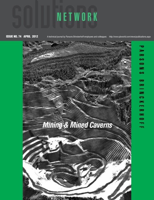
ISSUe NO. 74 APRIL 2012 A technical journal by <strong>Parsons</strong> <strong>Brinckerhoff</strong> employees and colleagues http://www.pbworld.com/news/publications.aspx<br />
<strong>Mining</strong> & <strong>Mined</strong> <strong>Caverns</strong><br />
P A r S o N S B r I N C k e r H o F F
Table of Contents<br />
APRIL 2012 http://www.pbworld.com/news/publications.aspx<br />
Introduction: Leadership in <strong>Mining</strong> and<br />
<strong>Mined</strong> <strong>Caverns</strong> – (Mark Dimmock) ...............................1<br />
MINING<br />
Feasibility Studies, Geological Assessments,<br />
Resource Estimation<br />
<strong>Mining</strong> Feasibility Studies – An Outline of the Technical<br />
Input, Requirements and Purpose of <strong>Mining</strong> Feasibility<br />
Studies – (Marco Maestri) ..........................................4<br />
Geological Assessment and Resource Estimation of<br />
Coal Deposits and Their Influence on Mine Design –<br />
(Aidan Parkes/Sam Moorhouse/Jonathan O’Dell) ........9<br />
The Relevance of International Reporting Codes and<br />
Their Practical Application to Resource Estimation –<br />
(Sam Moorhouse/Aidan Parkes) ...............................13<br />
Sustainability and Community Involvement<br />
Innovating a Better Environment Through a<br />
Sustainable Approach to <strong>Mining</strong> – (Ben Hall) ..............17<br />
Reshaping Social Impact Assessment: Implications<br />
for Resource Companies and Their Role in Housing<br />
Provision – (Ceit Wilson) ...........................................19<br />
Looking at <strong>Mining</strong> Differently - 3D Visualisation<br />
Helps to Take the Guess Work Out – (Alan Hobson/<br />
Dylan Swan) .......................................................... 22<br />
Conveyor Systems<br />
High Lift Belt Conveyors for Underground Hard Rock<br />
Haulage – (John C. Spreadborough) ..........................25<br />
Conveyor Technology Selection for a Large<br />
Copper Project – (Scott Tapsall) ................................30<br />
Network<br />
<strong>Mining</strong> & <strong>Mined</strong> <strong>Caverns</strong><br />
Guest Editors for this issue: Mark Dimmock and Nick Edmunds<br />
EPCM Risk Management<br />
<strong>Parsons</strong> <strong>Brinckerhoff</strong> Global <strong>Mining</strong> EPCM<br />
Risk Management: A Proactive Approach –<br />
(Jereme Evans) ..................................................... 33<br />
Stabilization of Mine Sites<br />
Fenwick Heap Stabilisation – (Russell Bayliss/Alan<br />
Common/Jeff Jennings)............................................36<br />
<strong>Mined</strong> Cavern Stability Survey and Risk Assessment<br />
for Multiple Use Storage Facilities – (Adrian Dolecki/<br />
Gideon Jones) ..........................................................41<br />
MINED CAVERNS AND UNDERGROUND<br />
TUNNELS<br />
<strong>Mined</strong> <strong>Caverns</strong><br />
Geologic / Hydrologic Requirements for Successful<br />
<strong>Mined</strong> Underground Hydrocarbon Storage <strong>Caverns</strong> –<br />
(Bruce Russell) ........................................................46<br />
A Conceptual Design for a Geological Disposal<br />
Facility for the UK’s Radioactive Wastes – (Steven<br />
Majhu/Peter Gaskell) ...............................................49<br />
<strong>Mined</strong> <strong>Caverns</strong> for Hydro-electric Projects –<br />
(Andrew Noble) ........................................................52<br />
Underground Tunnels<br />
Ground Observational Methods in <strong>Mined</strong> Tunnel<br />
Support Systems – ((Adrian Dolecki/Gideon Jones) ....55<br />
The Design of Sprayed Concrete Linings (SCL) to<br />
Form Junction Chambers for Tunnels in London Clay –<br />
(Binh Soo Liew/Terry Howes/Rory McKimm) ..............59<br />
Network<br />
Future Issue ............................................................62
In 2011, <strong>Parsons</strong> <strong>Brinckerhoff</strong> made the strategic decision<br />
to target the growing mining and resources market in<br />
a more focussed and comprehensive manner. On a global<br />
scale, the market offers substantial opportunities for mining<br />
services providers, both now and for the longer-term.<br />
Our clients have been telling us over recent<br />
times that what they are looking for is leadership – both<br />
in thought and delivery of their projects. When <strong>Parsons</strong><br />
<strong>Brinckerhoff</strong> established the global mining business one<br />
year ago, we did so with a vision of being a leading provider<br />
of EPCM (engineering-procurement-construction management)<br />
services, leveraging the participation of Balfour<br />
Beatty operating companies in the development of mining<br />
and resources infrastructure (pit to port) along the development<br />
spectrum (concept to commissioning).<br />
The intent was to harness the broad range of capabilities<br />
within <strong>Parsons</strong> <strong>Brinckerhoff</strong> and Balfour Beatty,<br />
while building further capability and capacity to present<br />
an attractive offering to the market – that of an integrated<br />
contractor and services provider bringing the best study,<br />
engineering and delivery leadership to mining projects.<br />
Our core strategy is in four parts:<br />
1. To acquire capability in the key areas of process and<br />
mine planning;<br />
2. To continue our organic growth strategy of ‘following<br />
clients’ and diversifying across commodities;<br />
3. To leverage the capabilities of all Balfour Beatty operating<br />
companies; and<br />
4. To reinforce and develop core competency in delivery<br />
systems and procurement.<br />
We remain committed to our vision and strategy<br />
and have made considerable progress since inception of<br />
the business.<br />
Capability acquisition<br />
The first element of our strategy is to acquire mine planning<br />
and process engineering capability. These capabilities<br />
Network<br />
Leadership in <strong>Mining</strong> and <strong>Mined</strong> <strong>Caverns</strong><br />
by Mark Dimmock, Sydney, Australia, +61 2 92725183, mdimmock@pb.com.au<br />
Performance for the mining industry will come from leadership. Those companies that invest in leadership<br />
skills – both management and technical thought leadership – will be the winners. Technical innovations<br />
are a bi-product, rather than the driver of this.<br />
enable us to become involved in projects at the earliest<br />
stage, thereby developing stronger collaborative relationships<br />
with mining companies.<br />
Whilst we are active in the acquisition of companies<br />
with specialized mining capabilities, we have also<br />
deemed it prudent to develop our core capabilities organically.<br />
We are expanding our mining engineering capability<br />
from the UK, initially into regions in Africa. We<br />
are also pursuing organic growth in process engineering.<br />
Organic growth will provide us with a platform to<br />
leverage any acquisition, and an ability to more readily<br />
integrate any acquisition.<br />
Geographic and commodity expansion<br />
Currently, <strong>Parsons</strong> <strong>Brinckerhoff</strong>’s global mining business is<br />
effectively in three stages of maturity:<br />
1. Australia’s Hunter Valley and Queensland region is the<br />
most mature, based on <strong>Parsons</strong> <strong>Brinckerhoff</strong> having long<br />
established relationships with many coal-mining clients,<br />
including the large diversified mining companies.<br />
• In the Hunter Valley, <strong>Parsons</strong> <strong>Brinckerhoff</strong> is considered<br />
a leader in the mining sector – a reputation<br />
earned over many years of delivering high quality<br />
studies and successfully executing projects. That<br />
reputation was reinforced by the completion of the<br />
Mangoola Project with Xstrata Coal in 2011, ahead<br />
of time and under budget. <strong>Parsons</strong> <strong>Brinckerhoff</strong> is<br />
also delivering the Ulan Project for Xstrata Coal and<br />
the Bengalla Expansion for Rio Tinto & Westfarmers.<br />
• In Queensland, <strong>Parsons</strong> <strong>Brinckerhoff</strong> secured the provision<br />
of EPCM services for BHP Billiton Mitsubishi Alliance’s<br />
sustaining capital program. We are also continuing<br />
to conduct studies in this region for Xstrata<br />
and this is positioning us well for future delivery work.<br />
2. Western Australia, Southern Africa (South Africa and Mozambique)<br />
and Australia’s South Central region all have<br />
enormous forecast expenditure on mine infrastructure<br />
APRIL 2012 http://www.pbworld.com/news/publications.aspx Introduction<br />
1
Feasibility Studies, Geological Assessments, Resource Introduction Estimation<br />
APRIL 2012 http://www.pbworld.com/news/publications.aspx<br />
2<br />
and are emerging, or re-emerging, as significant regions<br />
where <strong>Parsons</strong> <strong>Brinckerhoff</strong> is building client relationships<br />
and establishing our business.<br />
• From the foundations established in the Western Australian<br />
region over the last several years, study work<br />
for Atlas Iron has converted into execution work. In<br />
addition, we have completed studies for many clients,<br />
and a number of the projects where we provided the<br />
studies are now moving to delivery, and we are wellplaced<br />
to continue working with these clients, which<br />
include Rio Tinto, Aston Resources and Xstrata Coal.<br />
• <strong>Parsons</strong> <strong>Brinckerhoff</strong> also secured the EPCM for a<br />
rail maintenance facility in Western Australia’s Pilbara<br />
region for Fortescue Metals Group, and continues to<br />
provide services to Arafura on its rare earth project.<br />
• Australia’s South Central is also re-emerging in the resources<br />
sector. The multi-award winning Jacinth-Ambrosia<br />
Mineral Sands Project, and the infrastructure<br />
study undertaken for government, has maintained<br />
our brand as a leading player.<br />
• In Africa, <strong>Parsons</strong> <strong>Brinckerhoff</strong> will be assisting Anglo<br />
Platinum as part of an owner’s team on two platinum<br />
projects in South Africa in 2012. Also, the Tweefontein<br />
Project in South Africa has now been endorsed<br />
by the Xstrata Coal board and is likely to proceed to<br />
execution this year.<br />
• We are currently completing the feasibility study for<br />
Eurasian Natural Resources Corporation’s (ENRC) Estima<br />
Project in Mozambique. In this project, we are<br />
responsible for the full study, including mining (UK<br />
team), process and non-process infrastructure.<br />
3. There are a number of new regions in which <strong>Parsons</strong><br />
<strong>Brinckerhoff</strong> is developing our mining business. These<br />
include Indonesia, Canada, Mongolia, and Brazil.<br />
In 2012, we will continue to strengthen our focus<br />
on client relationship management (CRM) and the differing<br />
needs of our clients.<br />
Balfour Beatty leverage<br />
<strong>Parsons</strong> <strong>Brinckerhoff</strong> is the professional services division<br />
of Balfour Beatty and, as such, continues to pursue joint<br />
opportunities with the overall Balfour Beatty group. This includes<br />
bidding on a number of projects with Balfour Beatty<br />
Rail in Asia and Southern Africa.<br />
A number of senior staff from Balfour Beatty’s<br />
construction businesses have been transferred to <strong>Parsons</strong><br />
<strong>Brinckerhoff</strong> in response to feedback from clients that our<br />
approach to EPCM is strengthened with a contractor’s perspective<br />
and strong leadership in managing projects. As our<br />
business grows in 2012, we will continue deploying staff<br />
from the broader group and reinforcing project leadership.<br />
Network<br />
Delivery systems<br />
<strong>Parsons</strong> <strong>Brinckerhoff</strong> has commenced its transition to<br />
an EPCM business, characterised by a department structure<br />
which includes: construction management, construction<br />
services, procurement, SHEQ (safety, health,<br />
environment, quality), and IR/HR (industrial relations/<br />
human resources). Department leaders are responsible<br />
for providing a consistent platform of policy, systems,<br />
processes and procedures. The advantages of this consistent<br />
approach across the business include an ability<br />
to quickly deploy knowledgeable staff to projects, and<br />
the ability to start a project with a readily mobilised system<br />
and experienced users.<br />
In 2012, we are also implementing a consistent,<br />
robust project controls system to further build and<br />
consolidate consistent excellence in project delivery.<br />
What makes us different?<br />
Our business model is to engage in projects at their<br />
earliest stage, working with our clients on evaluating the<br />
business case for their projects, and continuing our participation<br />
through to delivery. For us to be successful in<br />
this approach, we need to differentiate our offering.<br />
Our differentiators are our depth and experience<br />
across the Balfour Beatty group to complete the<br />
project and our very experienced study management<br />
team, supported by <strong>Parsons</strong> <strong>Brinckerhoff</strong>’s broad range<br />
of engineering capabilities. We have developed a global<br />
mining methodology for execution of studies and delivery<br />
of projects, with basic principles that can be readily<br />
applied to contracts in any region of the world.<br />
The mining services sector already has a number<br />
of significant global providers. So what will make us<br />
stand out from the crowd? Our ability to lead the way in<br />
integrating the very best thinking on mine planning and<br />
processing with clever and innovative engineering solutions<br />
and flawless project delivery capabilities.<br />
In this issue: thought leadership<br />
and excellence<br />
The articles in this issue demonstrate the fine minds<br />
and capabilities <strong>Parsons</strong> <strong>Brinckerhoff</strong> has in place, underpinning<br />
our commitment to ongoing investment in<br />
mining services leadership.<br />
Network’s <strong>Mining</strong> & <strong>Mined</strong> <strong>Caverns</strong> issue commences<br />
at the same point our clients do, with articles that<br />
provide insight into the process of evaluating the resource,<br />
a particular expertise of our UK-based mining practise.<br />
Sustainability and social license is a critical aspect<br />
of mining and, in the second section of this edition,<br />
the articles demonstrate how <strong>Parsons</strong> <strong>Brinckerhoff</strong> is
applying technology and making a positive contribution.<br />
Our third section is focused on conveyor technology<br />
and provides two good case studies on evaluation<br />
and use of contemporary technologies. Other sections<br />
are themed around risk management, a pertinent<br />
area when it comes to mining, and <strong>Parsons</strong> <strong>Brinckerhoff</strong>’s<br />
work in supporting mining projects.<br />
<strong>Mined</strong> caverns and tunnels is a sector where<br />
<strong>Parsons</strong> <strong>Brinckerhoff</strong> is a leading player. These articles<br />
demonstrate our depth of experience and knowledge in<br />
the space. Those pertaining to caverns for hydrocarbon<br />
storage, radioactive waste storage, and hydro-electric<br />
Network<br />
projects illustrate applications for mined caverns in different<br />
market sectors while articles about ground observation<br />
methods and sprayed concrete linings demonstrate<br />
the methodologies that we have employed.<br />
I have enjoyed serving as guest editor for this<br />
publication on mining and mined caverns, and appreciate<br />
the effort by all of the authors to share their knowledge<br />
and lessons learnt. I also want to thank the other<br />
guest editor, Nick Edmunds; the guest reviewers, Tim<br />
Smirnoff, Joanne Conradi, Graham Sterley, Tim Reichwein;<br />
and the editors, John Chow and Susan Lysaght, for<br />
their work on compiling and organizing this publication.<br />
Mark Dimmock<br />
Managing Director of Global <strong>Mining</strong><br />
Introduction<br />
APRIL 2012 http://www.pbworld.com/news/publications.aspx<br />
3
Feasibility Studies, Geological Assessments, Resource estimation<br />
APRIL 2012 http://www.pbworld.com/news/publications.aspx<br />
4<br />
<strong>Parsons</strong> <strong>Brinckerhoff</strong> is currently focussed on feasibility<br />
studies in Africa, with an emphasis on coal prospects.<br />
This article highlights the process of a typical study with<br />
a discussion on common pitfalls and a case study.<br />
<strong>Mining</strong> Development Process<br />
Once an exploration resource with sufficient potential<br />
to warrant further investigation is discovered – and that<br />
can prove to be a lengthy and expensive process – the<br />
process of securing funding and carrying out a series of<br />
feasibility studies begins. A mining feasibility study is an<br />
important evaluation tool to assess the economic and<br />
technical feasibility of the project, as well as to identify<br />
flaws (fatal or otherwise) as part of the associated risk<br />
assessment. The context and process leading up to the<br />
implementation of mining is shown in Figure 1.<br />
The ultimate purpose of a feasibility study should be:<br />
1. To define and assess the project - specifically:<br />
• Scope<br />
• Technical nature<br />
Network<br />
<strong>Mining</strong> Feasibility Studies - An Outline<br />
of the Technical Input, Requirements and<br />
Purpose of <strong>Mining</strong> Feasibility Studies<br />
by Marco Maestri, Godalming, UK, maestrim@pbworld.com, +44(0)7917 212350<br />
Figure 1 - <strong>Mining</strong> Development Process<br />
• Project resources and reserves<br />
• Costs<br />
• Schedule<br />
• Economics<br />
• Risks<br />
2. As a sales document – used to support funding and<br />
offer confidence to investors who may not have technical<br />
expertise or access to the technical data. Scandals<br />
involving the corruption of raw data have led to<br />
the implementation of international reporting standards<br />
– the most notable of which include the JORC<br />
code (Australia), SAMREC code (South Africa) and NI<br />
43-101 (Canada). Adherence to these codes ensures<br />
consistency in the level of confidence and language<br />
on which lay persons (investors) can rely.<br />
3. As a planning document – at each stage the previous<br />
study should act as a ‘blueprint’ for the next<br />
level – e.g., a prefeasibility study should act as a<br />
planning document for the definitive feasibility study<br />
and so on.<br />
Typically, <strong>Parsons</strong> <strong>Brinckerhoff</strong> would concentrate<br />
on (1) and (3) from the list above and, as an independent<br />
consultant, would not be involved in the<br />
marketing of a resource development project, having to<br />
maintain a degree of independence from this process.<br />
Accuracy<br />
Feasibility studies are often prefaced with a term indicating<br />
the level of study accuracy: ‘preliminary’, ‘pre’, ‘final’,<br />
‘bankable’, ‘definitive’ are some of the terms often<br />
seen in the industry and understanding what they mean<br />
is an important part of the process. A list of common<br />
names used in the industry is shown in Figure 2, with<br />
the <strong>Parsons</strong> <strong>Brinckerhoff</strong> standard terminology shown in<br />
the top boxes.
Figure 2 - Common Names Used for the Feasibility Study Stages<br />
What Is Involved?<br />
A mining feasibility study is a multi-disciplinary evaluation<br />
of a mining project that integrates all facets of the<br />
mining business, including technical, political, regulatory,<br />
environmental and economic facets. High-level<br />
factors that require consideration in a feasibility study<br />
are shown in Figure 3.<br />
The complete mining life cycle is shown in Figure<br />
4, giving context to feasibility studies (shaded).<br />
Figure 3 - Feasibility Study Inputs<br />
Network<br />
The levels of study are:<br />
Scoping Study. A scoping study is carried out very early<br />
in the project life to determine if the project is economically<br />
viable and technically feasible. It may be used as<br />
a basis for acquiring exploration areas or making a commitment<br />
for exploration funding. A high-level mining scenario<br />
is usually considered at this stage, along with a<br />
risk assessment and a fatal flaw analysis, to highlight<br />
any potential ‘show stoppers’. At scoping level, the investment<br />
risk may be relatively small but it is obviously<br />
undesirable to expend further funds on something that<br />
has no chance of being economically viable.<br />
Scoping studies typically have an estimation accuracy<br />
of +/- 30%. A scoping study determines whether<br />
the expense of a full prefeasibility study is warranted.<br />
Prefeasibility Study (PFS). A prefeasibility study is a<br />
comprehensive study whose main features are:<br />
• Completion of a geological assessment and resource<br />
estimate, which will quantify the tonnage and quality<br />
of the mineral deposit. The resource will be quan-<br />
Feasibility Studies, Geological Assessments, Resource Estimation<br />
APRIL 2012 http://www.pbworld.com/news/publications.aspx<br />
5
Feasibility Studies, Geological Assessments, Resource Estimation<br />
APRIL 2012 http://www.pbworld.com/news/publications.aspx<br />
6<br />
Figure 4 - <strong>Mining</strong> Project Life Cycle<br />
tified according to recognised international resource<br />
reporting standards (see “The Relevance of International<br />
Reporting Codes and Their Practical Application<br />
to Resource Estimation”, in this publication);<br />
• Production of a geological model to be used as a basis<br />
for mine design (see “Geological Assessment and<br />
Resource Estimation of Coal Deposits and Their Influence<br />
on Mine Design” in this publication);<br />
• Investigation of the most suitable scale of operation;<br />
• Conducting a technical options study (on all mining,<br />
processing & civil engineering options);<br />
• Following the options study, selection of the best solution<br />
taken through to the definitive feasibility study<br />
(DFS) stage for detailed evaluation;<br />
• Completion of preliminary studies on geotechnical, environmental,<br />
and infrastructure requirements;<br />
• Completion of bench scale metallurgical tests and<br />
preliminary process design;<br />
• Estimation of cost based on factored or comparative<br />
prices; and<br />
• An assessment of the environmental and social fatal<br />
flaws. The environmental impact assessment (EIA)<br />
and the social impact assessment (SIA) process can<br />
be initiated at this stage.<br />
Prefeasibility studies typically have an estimation<br />
accuracy of +/- 20% to 25%. A prefeasibility study<br />
will determine whether or not to proceed with a definitive<br />
feasibility study. These studies are typically carried<br />
out by a third-party mining consultant (such as <strong>Parsons</strong><br />
<strong>Brinckerhoff</strong>). However, if the expertise is available and<br />
independence is not an issue then they can be completed<br />
by in-house teams.<br />
Network<br />
Definitive Feasibility Study. The definitive feasibility<br />
study, typically based on the most attractive alternative<br />
for the project as previously determined, is the most<br />
detailed and should remove all significant uncertainties<br />
and present the relevant information with back up material<br />
in a concise and accessible way. The definitive feasibility<br />
study has several objectives:<br />
• To demonstrate with reasonable confidence that the<br />
project can be constructed and operated in a technically<br />
sound and economically viable manner;<br />
• To provide a basis for detailed design and construction;<br />
• To enable finance for the project to be raised from<br />
banks or other sources; and<br />
• To provide the basis for permitting and regulatory approvals.<br />
The definitive feasibility study typically has an<br />
estimation accuracy of +/-10 to 15%.<br />
The Importance of Getting it Right<br />
The early stages of the feasibility study process are important<br />
– the scoping and prefeasibility study levels are<br />
when design options can be flexed and tested. It is acceptable<br />
for scoping studies to be based on very limited<br />
information or speculative assumptions in the absence<br />
of hard data. The study is directed at the potential of<br />
the property and the study should err on the side of<br />
optimism – getting it wrong at this stage will not be as<br />
costly as rejecting an otherwise economically viable project<br />
due to being too risk adverse.<br />
Influence on the outcome diminishes once the<br />
project has reached the definitive feasibility level, the<br />
options and design should be more or less fixed, with
Figure 5 - Leverage of Early Work<br />
only specifics to be decided upon, as Figure 5 illustrates.<br />
It is also important to remember that each<br />
stage of the process adds value and that the study process<br />
needs to be of the highest quality to deliver maxi-<br />
Figure 6 - Impact of Study Phases on Project Value<br />
mum value (see Figure 6). If something is missed or an<br />
optimal option is not investigated or selected, it is very<br />
difficult to realise the true value of the project.<br />
Common Pitfalls and Misconceptions<br />
The most common pitfalls and misconceptions that lead to<br />
the failure or under-performance of a feasibility study are:<br />
1. “Bankable” does not mean bankable. It is best to<br />
avoid using the emotionally charged term ‘bankable’<br />
feasibility study due to the misconceptions surrounding<br />
the word. Many clients believe that a ‘bankable’<br />
document is just that – a document that can be taken<br />
to a bank in exchange for cash. Unfortunately, this is<br />
not the case and the term is misleading. At the very<br />
least, the lender will require its own due diligence and<br />
internal review before any investment. Then the project,<br />
albeit economically feasible, may not meet the<br />
Network<br />
lenders criteria for investment.<br />
For this reason,<br />
<strong>Parsons</strong> <strong>Brinckerhoff</strong> uses<br />
the term ‘definitive’ feasibility<br />
study, which should<br />
achieve the minimum criteria<br />
to facilitate the procurement<br />
of bank debt.<br />
2. Failure to integrate<br />
study disciplines. Having<br />
study contributors operating<br />
in isolation can lead<br />
to failure to identify fatal<br />
flaws or material issues.<br />
<strong>Parsons</strong> <strong>Brinckerhoff</strong> acts as overall project manager<br />
for the studies we are involved in and completes 75%<br />
in-house which helps to mitigate this issue.<br />
3. Failure to peer review the document. Failure to conduct<br />
a thorough peer review<br />
with ‘outsiders’ eyes<br />
leads to groupthink and<br />
an unhealthy emotional<br />
attachment to a project.<br />
4. Failure to involve all<br />
stakeholders. A comprehensive<br />
stakeholder analysis<br />
and communication<br />
plan is required to ensure<br />
all stakeholders are kept<br />
‘in the loop’. This ensures<br />
that misunderstandings<br />
and late scope changes<br />
are kept to a minimum.<br />
5. Should be ‘Fit for Purpose’. Studies all too often concentrate<br />
time and effort (and, importantly, money) on<br />
relatively unimportant technical issues (e.g., overanalysing<br />
preliminary data) at the expense of critical<br />
business and project delivery issues.<br />
6. Poor housekeeping. Geological interpretation is the<br />
basis of any study. A rigorous QA/QC must be carried<br />
out on the geological database before undertaking a<br />
project or design to understand the validity/state of<br />
the data.<br />
7. A feasibility study is not a guarantee of success. A<br />
feasibility study is just that – a study to determine<br />
whether or not a project is feasible from a technical,<br />
regulatory and financial point of view. Just because<br />
a project is undergoing a feasibility study does not<br />
mean that the results will be positive.<br />
8. Poor continuity. All too often, the handover from one<br />
study to another (for example, from prefeasibility study<br />
Feasibility Studies, Geological Assessments, Resource Estimation<br />
APRIL 2012 http://www.pbworld.com/news/publications.aspx<br />
7
Feasibility Studies, Geological Assessments, Resource Estimation<br />
APRIL 2012 http://www.pbworld.com/news/publications.aspx<br />
8<br />
<strong>Parsons</strong> <strong>Brinckerhoff</strong> Case Study<br />
In 2009, <strong>Parsons</strong> <strong>Brinckerhoff</strong> was commissioned<br />
to undertake both pre-feasibility (+/-25%) and definitive<br />
feasibility (+/-10%) studies on a coal resource<br />
in the Waterberg area of South Africa, located 5km<br />
to the west of the Grootegeluk Colliery and the Medupi<br />
Power Station. This was a large project with production<br />
rates of up to 15 million tonnes per annum<br />
(Mtpa) of run-of-mine (ROM) coal yielding 10Mtpa of<br />
saleable thermal coal over a 21 year mine life.<br />
The studies included a detailed investigation<br />
of the requirements for on-site and off-site infrastructure,<br />
mine design and scheduling, engineering, coal<br />
handling and preparation, hydrogeology and geotechnical<br />
engineering & personnel and equipment. This<br />
is an example of a large multi-disciplinary project<br />
with several contributors with integration of inputs<br />
between the various disciplines key to the success.<br />
The client was a joint venture between two<br />
companies – one based in South Africa and one in<br />
Australia. As the project was being managed out of<br />
the UK, effective communication and engaging the<br />
various stakeholders was essential.<br />
to definitive feasibility study) is not as effective as it<br />
should be, which leads to ineffective knowledge transfer.<br />
This could result in reduced value in the original<br />
study, missing a key conclusion or unnecessary re-work.<br />
Innovation within the feasibility study<br />
process<br />
Innovation within the feasibility study process is interlinked<br />
with innovation within the mining industry as a<br />
whole. Assuming that a feasibility study has to assess<br />
three main criteria - technical, regulatory and economic<br />
- possible innovations in these categories, which will<br />
change the way projects are assessed or the assessment<br />
itself, are shown below:<br />
1. Technical. This category covers a wide range: resource<br />
identification and verification, mineral extraction, processing,<br />
haulage technology, amongst many others.<br />
Once the resource in the ground has been verified,<br />
the way it is extracted, processed and delivered to<br />
the market determines whether a project is feasible<br />
or not. Advances in technology - such as automated<br />
mining equipment or x-ray sorting processing methods<br />
- can result in a previously un-feasible project becoming<br />
viable and keeping on top of new technology<br />
is an integral part of the feasibility process.<br />
2. Regulatory. There is a growing movement toward sus-<br />
Network<br />
tainable development and social responsibility in the<br />
industry. Guidelines now require compliance. Expect<br />
environmental controls to get tighter in the future<br />
and compliance will play a major role in the feasibility<br />
study process, even more so than now. Additionally,<br />
government intervention, such as high taxes or nationalisation,<br />
especially in developing countries, may<br />
have a big impact on whether a project could be considered<br />
feasible or not.<br />
3. Financial. Because mining is a mature industry, nearly<br />
all of the extremely attractive projects - the ‘low lying<br />
fruit’ - have been developed, and most mining studies<br />
are of a marginal nature when assessed using traditional<br />
feasibility techniques. The risk is, of course,<br />
that the assessment is too cautious and focused on<br />
the downside, which means that good projects are<br />
potentially being rejected at the feasibility stage.<br />
The traditional valuation technique for a feasibility<br />
study is a discounted cash-flow (DCF) model which<br />
is well understood and deals with costs and revenue. An<br />
alternative method of valuing a mining project that could<br />
be adopted is the real options analysis (ROA) method.<br />
The ROA method places a value on ‘real options’ when<br />
undertaking certain true-to-life business decisions, such<br />
as deferring, abandoning, expanding, staging, or contracting<br />
a capital investment project. Although there is<br />
some similarity between modelling real options and financial<br />
options, ROA takes into account uncertainty surrounding<br />
the parameters that determine the value of the<br />
project and applies a value to the company’s ability to<br />
respond to them. On the whole, ROA valuation methods<br />
are seen as more ‘optimistic’ than classic DCF methods<br />
and could be usefully employed when assessing more<br />
marginal studies, although the risk involved will also<br />
need to be properly assessed and communicated.<br />
Marco Maestri is a principal mining engineer whose expertise<br />
lies in feasibility studies, project management, CAD mine design<br />
& scheduling and financial analysis. He is currently the project<br />
manager for a pre-feasibility project in the Limpopo region of<br />
South Africa and has recently managed a successful coal definitive<br />
feasibility study in the same region. He also has experience<br />
managing and providing technical input to feasibility projects in<br />
Europe and Australia.<br />
References<br />
• The Role of Feasibility Studies in <strong>Mining</strong> Ventures (Nethery,<br />
2003)<br />
• The Use and Abuse of Feasibility Studies (Mackenzie &<br />
Cusworth, 2007)<br />
• Mine Investment Analysis (Gentry & O’Neil, 1984)
Network<br />
Geological Assessment and Resource<br />
estimation of Coal Deposits and Their<br />
Influence on Mine Design<br />
by Aidan Parkes, Manchester, UK, +44 (0)161-200-5178, aidan.parkes@pbworld.com; Samuel Moorhouse, Manchester,<br />
UK, +44 (0)1612-200-9847, sam.moorhouse@pbworld.com; and Jonathan O’Dell, Manchester, UK, +44 (0)1612-<br />
200-2216, jonathan.odell@pbworld.com<br />
<strong>Parsons</strong> <strong>Brinckerhoff</strong> has undertaken a number of feasibility<br />
studies for coal deposits in sub-Saharan Africa<br />
(see “<strong>Mining</strong> Feasibility Studies - An Outline of the Technical<br />
Input, Requirements and Purpose of <strong>Mining</strong> Feasibility<br />
Studies”, this publication), to determine the economic<br />
viability of extracting these potential resources.<br />
The feasibility process and reporting of mineral deposits<br />
is governed by a number of international codes, and<br />
associated guidelines (see “The Relevance of International<br />
Reporting Codes and Their Practical Application to<br />
Resource Estimation”, this publication).<br />
An important aspect of the feasibility study<br />
process is the undertaking of a geological assessment<br />
and resource estimation, which will quantify the tonnage<br />
and quality of the mineral deposit. To do this the<br />
Competent Person (CP) must demonstrate an understanding<br />
of the geology of the deposit, in particular its<br />
extent, quantity and quality, as well as any associated<br />
geological structures. The resource can then be classified<br />
based on the CP’s confidence of the available data,<br />
and quantified according to international resource reporting<br />
codes.<br />
The geological assessment and resource estimation<br />
process is a prerequisite for robust appraisal<br />
of mining potential including mine design, planning and<br />
scheduling (Figure 1). This article summarises the key<br />
stages in the assessment process and highlights some<br />
novel approaches employed by <strong>Parsons</strong> <strong>Brinckerhoff</strong> geologists<br />
during the various feasibility studies.<br />
Stage 1: Data selection and audit<br />
The goal of the selection and audit process is to produce<br />
a robust, finalised database, comprising suitable<br />
spatial, geological and quality data (Table 1), upon which<br />
a geological model can then be constructed.<br />
Data selection involves a detailed assessment<br />
of the data made available to <strong>Parsons</strong> <strong>Brinckerhoff</strong> by its<br />
clients. The CP will identify reliable information, discarding<br />
that without a verifiable audit trail.<br />
Once the finalised dataset has been selected, a<br />
thorough audit process is performed through systematic<br />
and comprehensive validation of raw data, to ensure:<br />
• Borehole locations and license boundaries use the<br />
same co-ordinate system;<br />
• Stratigraphical depths are consistent between handwritten,<br />
geophysical logs and sample intervals;<br />
• Coal analyses match laboratory certificate sheets,<br />
and are accurate; and<br />
• Statistical analysis of laboratory results is performed<br />
to identify any abnormal values.<br />
In a recent study, it was found that sampling<br />
had been completed on an ad-hoc basis instead of the<br />
recommended approach of using depths that relate<br />
directly to lithology, as per the geophysical logs. This<br />
resulted in the mismatching of drilling, lithology, and<br />
sample depths between boreholes, making it necessary<br />
to adjust sample depths to ensure compatibility<br />
with the geophysical logs.<br />
Data quality issues were overcome by using<br />
the percentage of core recovered during drilling (“core<br />
recovery”) as a direct indicator of data reliability. Because<br />
sections of poor core recovery (often relating<br />
to minor faulting) lacked adequate sample data and<br />
subsequent analysis, they were deleted from the database.<br />
Here, where insufficient analytical data was<br />
unavailable, resources were downgraded during classification,<br />
and greater geological losses were applied<br />
(Stage 3 below). This methodology allowed integration<br />
of the core recovery, sample, and lithology datasets<br />
despite their apparent depth differences.<br />
Feasibility Studies, Geological Assessments, Resource Estimation<br />
APRIL 2012 http://www.pbworld.com/news/publications.aspx<br />
9
Feasibility Studies, Geological Assessments, Resource Estimation<br />
APRIL 2012 http://www.pbworld.com/news/publications.aspx<br />
10<br />
DATA TYPE<br />
Spatial<br />
Geological<br />
Quality<br />
Network<br />
Figure 1 – The four key stages in the geological assessment and resource estimation process<br />
Survey of borehole locations<br />
Digital terrain models<br />
Boreholes<br />
Geophysical logs<br />
Outcrop<br />
Maps<br />
Aerial geophysics<br />
Seismic surveys<br />
Core recovery<br />
Coal samples<br />
Table 1 – Components of the geological database<br />
SOURCES RATIONALE<br />
Enables the spatial context of geological and<br />
quality data to be established<br />
Topographical surfaces provide physical constraint on the extent<br />
of coal seams and are used as an elevation reference surface<br />
Provide the basic framework of coal seam<br />
positions and dimensions<br />
Laboratory analysis of coal samples (of different wash fractions)<br />
including raw density, calori�c value, yield, coking properties and<br />
percent of ash, moisture and sulfur, phosphorous, etc.
Stage 2: Geological modelling<br />
Construction of a geological model is fundamental to modern<br />
resource estimation, enabling the data collected for a<br />
deposit to be visualised, and its extent and quality to be<br />
reliably and accurately quantified. Furthermore, the model<br />
can then be submitted to mining engineers as a basis for<br />
subsequent mine design.<br />
<strong>Parsons</strong> <strong>Brinckerhoff</strong> uses in-house geological<br />
modelling and resource estimation software 1 to produce<br />
accurate 3-D models of deposits. Data selected during the<br />
audit process (Stage 1) is imported into the software’s internal<br />
database management system 2 . Coal deposits are<br />
then modelled using the integrated stratigraphical modelling<br />
process (ISM) designed specifically for stratiform deposits<br />
(where the deposit forms a layer or layers within the<br />
stratigraphical sequence). The ISM approach comprises 5<br />
key steps (Table 2).<br />
Steps Purpose<br />
1: Data Validation<br />
Testing the database for<br />
potential sources of error<br />
2: Interpolation of<br />
drill hole data<br />
3: Modelling of stratigraphy<br />
4: Compositing and modelling<br />
of qualities<br />
5: Construction of Horizon<br />
Adaptive Rectangular Prism<br />
(HARP) block model<br />
Table 2 - The basic steps of geological modelling<br />
Interpolation of geological<br />
data between boreholes<br />
Generation of a stack of 3-D<br />
surfaces for the roof (top) and<br />
�oor (bottom) of each<br />
geographical unit.<br />
Compositing of analytical data<br />
for each geological unit to<br />
produce a single range of coal<br />
qualities, which are then<br />
extrapolated for the site.<br />
Construction of a block<br />
model. Individual blocks<br />
contain all geological and<br />
quality data for the 3-D space<br />
it represents. Igneous<br />
intrusions and faults can be<br />
incorporated into the block<br />
model<br />
In a recent <strong>Parsons</strong> <strong>Brinckerhoff</strong> study, the block<br />
model produced in the above process contained approximately<br />
25,000 individual blocks for each coal seam and<br />
each block contained specific calculated quality parameters.<br />
This block model was then used as a basis for resource<br />
assessment and deductions made for other fac-<br />
Network<br />
1 <strong>Parsons</strong> <strong>Brinckerhoff</strong> global mining uses Maptek Vulcan® software to undertake geological modelling.<br />
2 Vulcan® uses Maptek Isis® database management system<br />
tors, such as faulting, weathering and igneous intrusions,<br />
as described below.<br />
The software is also capable of modelling orebodies<br />
(Figure 2). In a recent study, this methodology was<br />
used to digitise a series of dolerite intrusions (a basic igneous<br />
rock type) that were identified within a coal deposit using<br />
lithological and geophysical logs, and geological maps.<br />
<strong>Parsons</strong> <strong>Brinckerhoff</strong> geologists digitised the<br />
3-D shape of the intrusion by producing a series of polygons<br />
based upon borehole (vertical thickness of the intrusion)<br />
and outcrop data (the intrusion’s areal extent at<br />
surface). The polygons formed the frame for subsequent<br />
generation of a solid triangulation (a shape formed by<br />
numerous triangles).<br />
Furthermore, the methodology was also utilised<br />
to model the effects and extent of burning associated<br />
with the intrusion of hot magma next to the coal, enabling<br />
burnt coal to be quantified and classified differently.<br />
To do this the polygons produced were expanded<br />
by a distance determined from a study of the sample<br />
analyses, and a second triangulation produced. Once<br />
produced, the triangulations (3-D shapes) are incorporated<br />
into the block model, allowing an assessment of<br />
the quantity of the coal affected by the intrusion(s).<br />
Figure 2 – Modelling of ore-bodies and dolerite intrusions is performed<br />
using wire-frame / triangulation solids<br />
Stage 3: Resource classification and estimation<br />
Development of the block model enables accurate estimation<br />
of the resource, incorporating dimensions, tonnages<br />
and coal quality properties that vary spatially.<br />
The relative confidence of specific areas of the<br />
deposit is measured using a formal classification procedure<br />
as set out in existing international codes and<br />
Feasibility Studies, Geological Assessments, Resource Estimation<br />
APRIL 2012 http://www.pbworld.com/news/publications.aspx<br />
11
Feasibility Studies, Geological Assessments, Resource Estimation<br />
APRIL 2012 http://www.pbworld.com/news/publications.aspx<br />
12<br />
guidelines. <strong>Parsons</strong> <strong>Brinckerhoff</strong> widely uses the Australasian<br />
JORC Code although a number of codes exist<br />
internationally (see “The Relevance of International<br />
Reporting Codes and Their Practical Application to Resource<br />
Estimation”, this publication).<br />
Geological confidence is assessed in terms of<br />
quantity and quality of available data and the complexity of<br />
the structure of the deposit. Coal is formally categorised<br />
into different classifications: Measured, Indicated and Inferred<br />
categories (of decreasing confidence). The categories<br />
are each defined by pre-existing criteria and specific<br />
parameters governed by the codes.<br />
Stage 4: Influence on mine design<br />
Geological assessment and resource estimation are required<br />
prior to the mine design phase of feasibility studies,<br />
as they allow:<br />
• Production of a 3-D geological model that enables the<br />
properties of the mineral deposit to be assessed spatially;<br />
• Classification of the resource into Measured, Indicated<br />
and Inferred status. This determines the confidence attributed<br />
to the resource and whether there is scope for<br />
subsequent mine design to be implemented. Only Measured<br />
and Indicated resources (regarded as more reliable)<br />
may be considered as reserves;<br />
• Input of coal production/quality data into mineral processing<br />
software by mine designers for coal handling<br />
and preparation plant (CHPP) design; and<br />
• Understanding of the coal products that can be produced<br />
with specific characteristics that match the client’s requirements,<br />
as the block model can be used to output<br />
tonnages based on specific quality parameters.<br />
Risk Profiles and Management<br />
There are a number of potential risks that may affect a resource<br />
statement, including issues with data often related<br />
to poor practice during collection and analysis, geological<br />
uncertainty (i.e., continuity of the geology between boreholes)<br />
and the modelling process.<br />
To ensure that risk is kept to a minimum and that<br />
all estimates are similar to one another, a number of international<br />
reporting codes and guidelines exist. These codes<br />
and guidelines ensure that all geological assessments and<br />
resource estimates follow the same basic principles and<br />
provide details on best practices, including the spacing of<br />
boreholes for resource classification to the amount of core<br />
recovered during exploration drilling.<br />
The most commonly used international codes<br />
and guidelines are: the South African Code for Reporting<br />
of Exploration Results, Mineral Resources and Mineral<br />
Reserves (SAMREC); the Australasian Joint Ore Reserves<br />
Network<br />
Committee (JORC) and The Code for Reporting of Mineral<br />
Resources and Ore Reserves (the JORC Code); and, the<br />
Canadian National Instrument 43-101: Standards of Disclosure<br />
for Mineral Projects and the CIM Definitions Standard<br />
(NI-43-101).<br />
<strong>Parsons</strong> <strong>Brinckerhoff</strong>’s use of a staged approach<br />
to the assessment and resource estimation process<br />
is also an important control for reducing risk, enabling<br />
risks to be identified and managed at each stage<br />
of the process.<br />
Summary and Conclusions<br />
Geological assessments and resource models are an integral<br />
part of a feasibility study. When conducted by experienced<br />
and qualified geologists (Competent Persons)<br />
and in line with international reporting codes, they provide<br />
a technically accurate and certified resource assessment<br />
valued by the client. Resource reports are important because<br />
they:<br />
• Provide detailed assessments of the dimensions, tonnages<br />
and quality of a mineral deposit;<br />
• Serve as a precursor to further studies, estimating the<br />
value of a deposit and thus the likelihood of a projects<br />
financial reliability (i.e., the feasibility study);<br />
• Contain detailed geological information, preferably as<br />
a geological model, required for mine design, scheduling<br />
and the drawing up of potential mineral processing<br />
plants (e.g., CHPP); and<br />
• Are valuable as a stand-alone document (e.g., as a Competent<br />
Person’s Report) as they are recognised internationally,<br />
possibly assisting with client requirements, such<br />
as: raising of funds for further exploration; securing capital<br />
to begin extracting the deposit; providing the legal requirements<br />
necessary for listing associated companies<br />
on international stock exchanges/financial markets.<br />
Aidan Parkes is a mining geologist and has recently been involved<br />
in resource assessments for pre-feasibility and feasibility studies,<br />
constructing geological models for coal deposits in southern Africa.<br />
He has a BSc (Hons) in earth systems science and a PhD in glacial<br />
geomorphology.<br />
Sam Moorhouse is a senior geologist specialising in resource estimations<br />
for coal deposits in southern Africa and sedimentary deposits<br />
in China. He holds a MESci (Hons) in earth sciences from the University<br />
of Oxford and is a Fellow of the Geological Society of London.<br />
Jonathan O’Dell is chief geologist for <strong>Parsons</strong> <strong>Brinckerhoff</strong> and a<br />
Competent Person in coal geology. He has a broad range of experience<br />
working on coal deposits in the UK, Indonesia, South Africa,<br />
Bangladesh and Russia.
Network<br />
The Relevance of International Reporting<br />
Codes and Their Practical Application to<br />
Resource estimation<br />
by Samuel Moorhouse, Manchester, UK, +44 (0)161-200-9847 sam.moorhouse@pbworld.com; and<br />
Aidan Parkes, Manchester, UK, +44 (0)161-200-5178 aidan.parkes@pbworld.com<br />
<strong>Parsons</strong> <strong>Brinckerhoff</strong> undertakes resource assessments<br />
of mineral assets and commodities around the<br />
world. This article explains the methodology for estimating<br />
resources in compliance with international reporting<br />
codes and the protocols which must be adhered to.<br />
Abundant literature exists which discusses the nuances<br />
of the different reporting codes and guidelines; this paper<br />
summarises how they can be practically applied,<br />
with specific references to coal.<br />
The purpose of international reporting codes<br />
Reporting codes are internationally recognised documents<br />
that afford a standardised framework on which<br />
mineral resource estimates can be publically reported.<br />
To the geologist they also provide a mandatory system<br />
for resource classification; a method for separating resources<br />
into different categories of varying confidence<br />
levels. The presence of these guidelines affords comfort<br />
to asset holders and potential investors in that the reputation<br />
of individuals and companies are under scrutiny<br />
when they produce reports. Today,<br />
any public resource report<br />
must adhere to these codes.<br />
Where it all began<br />
In 1969 the share prices of<br />
Australian mining company<br />
Poseidon NL skyrocketed as<br />
the potential of their recently<br />
identified nickel (Ni) deposit<br />
was made public. This was initiated<br />
by a high Ni concentration<br />
quoted by local geological consultants,<br />
Burrill & Associates,<br />
and further compounded by the<br />
extraordinarily high Ni price, at<br />
the time induced by the Vietnam<br />
War. These events led to the infamous Poseidon Bubble,<br />
which eventually burst as the Ni concentration was found<br />
to be considerably lower than the value quoted, but only<br />
after Poseidon’s share price had climbed to $280 from<br />
$0.03. Later, in Indonesia, the Canadian Bre-X owned<br />
gold deposit was uncovered as a fraud after shavings of<br />
gold jewellery were identified in the samples, losing investors<br />
billions of dollars in the process. The economic<br />
repercussions of these events signalled the change in<br />
mining legislation and marked the inception of the reporting<br />
codes we use today.<br />
Detailed resource definitions accompany the<br />
codes in their respective guidelines, both of which vary<br />
between countries. Each set of guidelines relates to the<br />
dominant deposits and specific stratigraphical sequences<br />
endemic within that country. Whilst the language<br />
differs slightly, the principles behind the codes are the<br />
same (see Figure 1).<br />
A process of aligning international reporting<br />
codes is currently underway, and is being developed by<br />
Country Common abbreviation Reporting Code Coal Reporting Guideline<br />
Australia<br />
South Africa<br />
Canada<br />
Europe<br />
2004 JORC Code<br />
SAMREC<br />
NI 43-101<br />
PERC 2008<br />
The Australasian Code for Reporting of<br />
Exploration Results, Mineral Resources<br />
and Ore Reserves, by the Australasian<br />
Joint Ore Reserves Committee<br />
The South African Code for the<br />
Reporting of Exploration Results,<br />
Mineral Resources and Mineral<br />
Reserves<br />
Figure 1 – Components of the geological database<br />
National Instrument 43-101: Standards<br />
of Disclosure for Mineral Projects and<br />
the CIM De�nitions Standard<br />
Pan-European Code For Reporting of<br />
Exploration Results, Mineral Resources<br />
and Reserves<br />
Australian Guidelines for<br />
Estimating and Reporting of<br />
Inventory Coal, Coal Resources<br />
and Coal Reserves, 2003<br />
SANS 10320:2004: South African<br />
guide to the systematic<br />
evaluation of coal Resources and<br />
coal Reserves<br />
Geological Survey of Canada<br />
Paper 88-21: A Standardized<br />
Coal Resource/Reserve<br />
Reporting System for Canada<br />
Reporting for Exploration<br />
Results, Resources and<br />
Reserves for Coal<br />
Feasibility Studies, Geological Assessments, Resource Estimation<br />
APRIL 2012 http://www.pbworld.com/news/publications.aspx<br />
13
Feasibility Studies, Geological Assessments, Resource Estimation<br />
APRIL 2012 http://www.pbworld.com/news/publications.aspx<br />
14<br />
the Committee for Mineral Reserves International Reporting<br />
Standards (CRIRSCO). The current members<br />
and their associated standards are Australasia (JORC),<br />
South Africa (SAMREC), Canada (CIM), Europe (PERC),<br />
United States (SME), Chile (Comisión Minera de Chile)<br />
and very recently Russia (NAEN).<br />
Achieving code compliancy<br />
Here, JORC Guidelines for Coal are used as illustration.<br />
The guidelines stipulate that resources are classified<br />
and reported according to three basic principles that<br />
must be observed:<br />
Transparency: the provision of clear, unambiguous<br />
information.<br />
Materiality: all relevant data is presented to allow<br />
reasoned and balanced conclusions to be made by<br />
the reader.<br />
Competence: the report is based on work undertaken<br />
by the Competent Person (CP); an individual of recent<br />
relevant experience (typically five years) in a specific<br />
commodity, that is suitably qualified and who abides<br />
by an enforceable professional code of ethics (i.e. is a<br />
member of a recognisable professional body).<br />
The definition of a resource<br />
Resources simply refer to a mineral deposit that<br />
might, under assumed and justifiable technical and<br />
economic conditions, become economically extractable.<br />
The geologists’ role is to identify and assess<br />
these resources.<br />
The commonly quoted and often cited relationship<br />
between exploration results, resources and reserves (extract<br />
from 2004 JORC Code) is shown in Figure 2.<br />
Network<br />
Figure 2- General relationship between exploration results, mineral Resources and ore Reserves<br />
Resource classification<br />
Resources are sub-divided into different classifications,<br />
providing a platform on which the geologist can<br />
convey the varying levels of confidence across the deposit.<br />
Practically this translates to: the lower the quantity<br />
and/or quality of data, the lower the confidence,<br />
the lower the classification and the greater the losses<br />
applied to that region of the resource. In the JORC<br />
Code, a resource is classified into Measured, Indicated<br />
or Inferred categories.<br />
Progressing beyond resource to a reserve involves<br />
application of more rigorous and detailed criteria,<br />
“modifying factors”, which are relevant at that time. A<br />
reserve is deemed economically mineable and can only<br />
be generated from Measured and Indicated classifications.<br />
Reserves require development of a mine plan and<br />
schedules in further pre-feasibility and feasibility studies<br />
(see “<strong>Mining</strong> Feasibility Studies - An Outline of the<br />
Technical Input, Requirements and Purpose of <strong>Mining</strong><br />
Feasibility Studies”, this publication).<br />
Resource classification is realised through the<br />
application of points of observation (PoOs) which are<br />
intersections of strata (i.e., coal), at known locations,<br />
that provide information allowing the presence of a<br />
potential resource to be unambiguously determined.<br />
Practically, this denotes the requirement of obtaining<br />
sufficient quantity and quality of data to confidently determine<br />
the presence and the characteristics of a mineral<br />
deposit, primarily in the form of drilling boreholes<br />
and logging, sampling and analysing the core extracted<br />
from the boreholes.<br />
Quantity of information: Is the coal<br />
continuous?<br />
An increased density of PoOs within a given 3-dimensional<br />
space exudes greater confidence in the deposit.<br />
To achieve Measured status, a maximum<br />
borehole spacing of 500 metres<br />
is allowed, i.e., boreholes cannot<br />
be greater than this distance<br />
apart. Indicated status calls for 1km<br />
spacing, and for Inferred status up to<br />
4km is permitted.<br />
The purpose of these devised<br />
borehole locations are to satisfy<br />
the concept of continuity. Inferred<br />
and Indicated categories refer to coal<br />
where lateral continuity in the deposit<br />
can only be assumed but not verified.<br />
Measured coal has enough data<br />
available to confirm continuity.
Quality of information: Is the data robust?<br />
Data quality is investigated by thoroughly following the<br />
audit trail. The primary examples of these parameters<br />
include, but are not restricted to:<br />
• Borehole co-ordinates surveyed by reputable professionals;<br />
• Exploration boreholes drilled with a substantial amount<br />
of core recovered (normally >95%);<br />
• Signed handwritten lithological logs from the field geologist;<br />
• Geophysical logs;<br />
• Adequate quantity of coal sampled; and<br />
• Coal analysis carried out by an accredited laboratory.<br />
In many cases much of the above data can be<br />
absent. It is the role of the Competent Person to best<br />
decipher this information, accurately assess its reliability<br />
and determine how the resource should be classified.<br />
With lower certainty, greater losses are applied<br />
and the final quoted tonnage is lowered (see Figure 3).<br />
RESOURCE<br />
Low level of<br />
confidence<br />
Reasonable<br />
level of<br />
confidence<br />
High level of<br />
confidence<br />
Inferred<br />
Indicated<br />
Measured<br />
Figure 3 – Geological losses and classification<br />
20% deduction to<br />
Resource tonnage<br />
15% deduction to<br />
Resource tonnage<br />
10% deduction to<br />
Resource tonnage<br />
The deductions applied reflect the overall confidence<br />
in the deposit but are typically around 20-25% for<br />
the lowest levels, and relate to the quality and quantity<br />
of data available but also the assurance in the lateral<br />
continuity of the deposit between points of observation.<br />
Conclusions<br />
• Codes and guidelines are different. Codes refer to how<br />
the resource should be reported. Guidelines provide<br />
a “manual” for the geologist to follow, devised and<br />
refined based on the experience and work of many<br />
professionals over a number of years.<br />
• Guidelines are useful because they provide tangible<br />
requirements that resource exploration must satisfy.<br />
They help to justify the decisions made by the geologist<br />
during resource classification.<br />
• The geologist must be a Competent Person (CP). Previous<br />
experience of a deposit is vital for assessment<br />
and classification.<br />
• Whilst it can be easy to strictly follow guidelines from<br />
Network<br />
the outset, it can be useful for the CP to subjectively<br />
examine the data as a whole. By exercising their knowledge,<br />
experience and discretion, CPs can ask themselves:<br />
“How much do we really know about this deposit?”<br />
Applying a more generalised outlook to the data<br />
can help to move away from guideline specifics (such<br />
as precise borehole spacings and core recoveries).<br />
• Additional data, such as seismic and aerial geophysical<br />
surveys or geostatistical analysis, cannot be translated<br />
to specific PoOs but can still aid the CP in deducing<br />
that the mineral in question is laterally continuous.<br />
• Observing all aspects of the data together can lead<br />
to advantageous balancing of guideline “rules” (e.g.,<br />
abundant and wholly reliable data could permit the acceptance<br />
of wider borehole spacings. Conversely, absent<br />
information and complex geology could result in<br />
only closely-spaced boreholes being allowed).<br />
• It is important that the involvement of professionally<br />
qualified and experienced practitioners is sought at<br />
the very early stages of projects. This can optimize<br />
the approach to assessing a deposit and can significantly<br />
reduce costs.<br />
Future outlook<br />
Reporting codes and their guidelines have developed<br />
significantly since their inception in the 1970s. The result<br />
is a series of well-established documents familiar<br />
within the geological and mining community. However,<br />
this process is still ongoing, with the terminology of the<br />
different documentation in a constant process of being<br />
rewritten and updated. For example, a current topic of<br />
discussion is the definition of a resource, which JORC<br />
calls “a concentration or occurrence of material of intrinsic<br />
economic interest ... (of which) there are reasonable<br />
prospects for eventual economic extraction”.<br />
The clarity of this statement is under scrutiny due to<br />
the ambiguity associated with the term “reasonable<br />
prospects for eventual economic extraction”. The initial<br />
assessment of a deposit requires a judgement to<br />
be made by the CP with respect to the techno-economic<br />
factors likely to influence the prospect of economic<br />
extraction. These criteria are applied fully during conversion<br />
of resources to reserves through application<br />
of modifying factors (as discussed previously) but nevertheless<br />
an initial consideration of the extractability<br />
of a resource must be made early in the assessment<br />
process. Opinion may differ markedly between CPs<br />
and their interpretation of the ease of extraction of the<br />
mineral and knowledge of local mineral markets. JORC<br />
has recently (October 2011) called for views on such<br />
matters to be submitted by the mining community. Fur-<br />
Feasibility Studies, Geological Assessments, Resource Estimation<br />
APRIL 2012 http://www.pbworld.com/news/publications.aspx<br />
15
Feasibility Studies, Geological Assessments, Resource Estimation<br />
APRIL 2012 http://www.pbworld.com/news/publications.aspx<br />
16<br />
thermore, the Australian Securities Exchange is starting<br />
to diverge from JORC by developing its own code<br />
similar to the Canadian principles, which were set up<br />
by the Canadian Securities Administrators and therefore<br />
require an increased input from lawyers (instead<br />
of simply technically qualified persons) when writing or<br />
publishing public reports.<br />
Reporting codes and guidelines continue to<br />
evolve, with terminology, definitions and requirements<br />
being updated every few years. As the mining sector becomes<br />
a more global entity, new codes are being developed<br />
in emerging mineral economies, with the notable<br />
acceptance of the Russian NAEN code by CRIRSCO as<br />
recently as November 2011. <strong>Parsons</strong> <strong>Brinckerhoff</strong> con-<br />
Network<br />
tinues to flourish in this evolving environment utilising<br />
codes and guidelines from all over the world in their mineral<br />
assessments.<br />
Sam Moorhouse is a senior geologist specialising in resource<br />
estimations for coal deposits in southern Africa and sedimentary<br />
deposits in China. He holds a MESci (Hons) in earth sciences<br />
from the University of Oxford and is a Fellow of the Geological<br />
Society of London.<br />
Aidan Parkes is a mining geologist and has recently been involved<br />
in resource assessments for pre-feasibility and feasibility<br />
studies, constructing geological models for coal deposits in<br />
southern Africa. He has a BSc (Hons) in earth systems science<br />
and a PhD in glacial geomorphology.
Network<br />
Innovating a Better environment Through<br />
a Sustainable Approach to <strong>Mining</strong><br />
by Ben Hall, Brisbane, Australia +61 7 3854 6706, be1hall@pb.com.au<br />
<strong>Parsons</strong> <strong>Brinckerhoff</strong> has been in the fortunate position<br />
of assisting a client, Sirius Minerals, with an innovative integration<br />
of engineering solutions which presents an environmentally<br />
and commercially positive approach to several<br />
major environmental issues currently being faced by<br />
Queensland, Australia.<br />
Sirius Minerals approached <strong>Parsons</strong> <strong>Brinckerhoff</strong><br />
to undertake an input study for the requirements of a solution<br />
potash mine in the middle of Queensland. Preliminary<br />
information gathered during some drilling operations indicated<br />
that the size of the salt member containing the potash is<br />
several tens of cubic kilometres, which is currently Australia’s<br />
largest documented salt deposit. With potash prices on<br />
the increase, this deposit is raising a fair degree of interest.<br />
The mining technique known as solution mining<br />
appears to be the most suitable approach based on the<br />
geology of the deposit. The process requires the pumping of<br />
large volumes of water into the salt member, the salt is then<br />
dissolved into the water and pumped back to the surface.<br />
The salt is processed out and the water is returned to the<br />
mining process. Herein lay the first major consideration<br />
for the project – sourcing water in<br />
an environmentally responsible manner while<br />
maintaining strong project economics.<br />
Sourcing water<br />
The centre of Queensland is quite hot and<br />
dry with evaporation rates over 2.5m (8.2ft)<br />
per year (see Figure 1).<br />
Sirius Minerals asked <strong>Parsons</strong> <strong>Brinckerhoff</strong><br />
to consider a solution mining operation<br />
that has the potential to extract over 5 million<br />
tonnes per year of potash salt. Solution mining<br />
at that scale of operation would require a<br />
water supply in the order of 20-30 gigalitres<br />
per annum. At the location of the salt member,<br />
there are no major waterways or dams.<br />
While there are several traditional options for<br />
obtaining water in such a situation, they are<br />
either costly or have potential environmental<br />
consequences, such as lowering the water table or diverting<br />
natural drainage. Therefore the first challenge was to<br />
identify a large volume of water that would be inexpensive<br />
and environmentally neutral or positive.<br />
Coal seam gas water<br />
The coal seam gas (CSG) industry in Queensland is providing<br />
promising economic opportunity and is expanding<br />
rapidly. However, the process of extracting gas from coal<br />
seams also generates a high volume of water. This water<br />
is saline and is a significant environmental issue. Public<br />
outcry against the salt deposits left by evaporation ponds<br />
(used to dispose of large amounts of water in the preliminary<br />
stages of the CSG industry) led to the Department<br />
of Environment and Resource Management issuing<br />
a moratorium in early 2011 on all new evaporation ponds,<br />
leaving the CSG producers to find an alternative way to<br />
deal with these vast volumes of water. The cost of dealing<br />
with the waste water and its salt content is currently<br />
estimated at over 2 billion dollars and likely to increase.<br />
Figure 1 – Evaporation rates for Australia (source: Australian Bureau of Meteorology)<br />
Sustainability and Community Involvement<br />
APRIL 2012 http://www.pbworld.com/news/publications.aspx<br />
17
Sustainability and Community Involvement<br />
APRIL 2012 http://www.pbworld.com/news/publications.aspx<br />
18<br />
The <strong>Parsons</strong> <strong>Brinckerhoff</strong> planning team working<br />
on the background study suggested that there may be a<br />
synergy between the coal seam gas producers, for whom<br />
the water is a waste product, and our client, Sirius Minerals.<br />
Sirius Minerals, who by the nature of solution mining<br />
of salts is already expert in the processing of salt containing<br />
water, was very receptive to the idea and this suggestion<br />
immediately sparked a flood of creative ideas. It<br />
was proposed that the coal seam gas produced water be<br />
pumped to central Queensland via a 500km pipeline and<br />
brought to the project site where it could be treated and<br />
used as process water.<br />
Power supply<br />
The second major consideration for the project is finding sufficient<br />
power for the operation of the solution mining, ideally<br />
drawing on renewable resources. Queensland already has<br />
a shortfall in reserve energy generation capacity, which has<br />
been predicted to grow to between 341 and 779 megawatts<br />
by 2013-2014. 1 As such, drawing hundreds of megawatts<br />
of capacity from the grid is not likely to be a viable option.<br />
For this reason many regional miners build their own power<br />
infrastructure, using either coal or natural gas. Carbon considerations<br />
and rising natural gas prices have increased the<br />
costs associated with coal and gas power and, therefore,<br />
renewable options are attracting more attention.<br />
Solar power is now a viable and cost effective<br />
option for Queensland due to the many days of sunshine<br />
prevalent in the region, but without a storage solution solar<br />
power cannot supply the consistent power needed for<br />
24/7 mining operations. However, given the suitable climate,<br />
large amounts of available land and the significant<br />
source of saline water in the CSG wastewater, another<br />
technology presents itself as a solution.<br />
Solar thermal pond power generation using Organic<br />
Rankine Cycle power plants is a technology that has proved<br />
effective in areas where there is high solar exposure and<br />
large areas of flat land, one of the most well known power<br />
plants of this type being the Bet Ha-Arava 5MW pond<br />
in Israel. The solar exposure in central Queensland is very<br />
high, and the terrain is quite flat. High levels of salt are also<br />
required, and CSG water is saline. Based on the technology<br />
used in Israel, a 20 hectare solar thermal pond can<br />
generate 5MW of power at the minimum and, with recent<br />
advances, potentially up to 20% more.<br />
A site layout has been proposed consisting of 24<br />
solar ponds with their associated evaporation ponds, and a<br />
collection dam. This arrangement would be able to receive<br />
1 http://www.aemo.com.au/planning/0410-0088.pdf<br />
Network<br />
suitable volumes of water produced from CSG and would<br />
allow for a minimum of 120MW of power generation. The<br />
layout is expandable, such that more ponds could be built<br />
to allow for greater power generation capacity. This might<br />
be used to run additional industrial operations or to provide<br />
cheap, baseload renewable power to the Queensland<br />
electricity grid.<br />
excess salt<br />
During the life cycle of a solar pond, water is evaporated<br />
from the surface of the pond and the salt remains. The salinity<br />
within the pond can get to levels that reduce the efficiency<br />
of the power generation. Periodically, highly saline<br />
water is removed from the pond and placed into evaporation<br />
ponds where the salt will crystallize and then require<br />
disposal. Disposal of this salt is presently a highly sensitive<br />
environmental issue in Queensland and the project needed<br />
a comprehensive and politically acceptable way of dealing<br />
with the generated salt.<br />
A potash mine also produces large volumes of sodium<br />
chloride (NaCl) as a by-product. This is often re-injected<br />
back into the mine, although it can also be further processed<br />
into other commercial salt products. One such process is<br />
the chlor-alkali process, which converts sodium chloride into<br />
caustic soda for direct sale into the Australian market.<br />
The power produced by the solar ponds would<br />
be enough to run a small scale chlor-alkali plant. Between<br />
the solar ponds and the potash mine, a significant<br />
quantity of high purity (ideal for chlor-alkali) sodium<br />
chloride will be produced. This would be sent to the<br />
chlor-alkali plant for processing, and the lower purity<br />
NaCl from both the ponds and the potash mine would<br />
be re-injected back into the mine.<br />
The concept design process has been closely<br />
integrated with Sirius Minerals who is very receptive of,<br />
and indeed generates, new and innovative ideas. By combining<br />
knowledge from across the breadth of <strong>Parsons</strong><br />
<strong>Brinckerhoff</strong>, and including alternative technologies and<br />
approaches, this project shows the potential to address<br />
major environmental challenges as part of the design of<br />
mining and process industries.<br />
For more information on this project, please visit<br />
the Sirius Minerals website: http://www.siriusminerals.com<br />
Ben Hall is project manager and team leader in the mechanical<br />
engineering group in Australia. He has over 10 years of experience<br />
and his particular interest is combining engineering services with<br />
sustainable practice in the environmental and commercial sectors.
Network<br />
Reshaping Social Impact Assessment:<br />
Implications for Resource Companies and<br />
Their Role in Housing Provision<br />
by Ceit Wilson, Brisbane, Australia, +61 7 38546766, cwilson@pb.com.au<br />
The Bowen Basin holds the largest coal reserves in Australia,<br />
with deposits covering a total approximate area<br />
of 60,000km 2 . The rapid expansion of the mining industry<br />
and accompanying population growth in this region<br />
has placed significant pressure on already limited social<br />
infrastructure existing in local rural and regional communities.<br />
In particular, most resource towns have experienced<br />
recurring housing shortages and ongoing housing<br />
affordability concerns.<br />
Dealing with these impacts is posing significant<br />
planning challenges not only for government, but<br />
increasingly for mining companies. In parallel with the<br />
growth in mining development, there has been a growing<br />
movement in the industry towards more social responsibility<br />
and sustainable development. However, the<br />
absence of a governance or regulatory framework for<br />
managing housing impacts has left some operations illprepared<br />
to meet these changing expectations.<br />
This article discusses the role mining companies<br />
have taken in the planning and delivery of housing<br />
infrastructure within the Bowen Basin and explores<br />
the changing legislative environment which is currently<br />
shaping their response to housing impacts.<br />
The Role of <strong>Mining</strong> Companies in<br />
Housing Provision<br />
In Queensland, most mining companies assist their<br />
workforce and the broader community in attaining housing<br />
and accommodation through a range of formal and<br />
informal housing policies. These include:<br />
• Private workforce accommodation provision and subsidisation<br />
policies, for example, on-site accommodation<br />
for Fly-in Fly-out (FIFO) and Drive-in Drive-out (DIDO)<br />
workforces, local rental or purchasing subsidies;<br />
• Internal company employment policies and plans (e.g.<br />
preferencing local resident labour first);<br />
• Public-private land and housing development partner-<br />
ships (e.g. with local governments and commercial<br />
housing providers); and<br />
• Public-private community services partnerships and<br />
plans (e.g. provision of housing and employment to<br />
community workers, such as doctors).<br />
The range of these housing strategies demonstrates<br />
that mining companies have considerable interest<br />
in, and control over, the provision of housing infrastructure<br />
to the communities in which they operate. This<br />
reflects several factors, including a change in tax and<br />
regulatory environment in Queensland, which has led<br />
mining companies to employ accommodation models<br />
with a greater focus on operational costs rather than<br />
a capital focus. These housing strategies also cater to<br />
the ‘normalised’ contemporary planning environment<br />
and the lifestyle-related preferences of employees. They<br />
also attempt to address the displacement of broader<br />
community members who, without the ‘mine salary’<br />
or employer support, are more vulnerable in a housing<br />
pressure environment. This role is typically undertaken<br />
through public-private partnerships (e.g., with local governments,<br />
commercial organisations or local community<br />
housing providers) and may be viewed as a positive example<br />
of industry partnerships driven by corporate social<br />
responsibility (CSR) considerations.<br />
From a planning perspective, these housing<br />
strategies can seem to be ad-hoc, isolated and reactive.<br />
In many cases, broader community provision is driven by<br />
the need to secure mineworkers and key service workers<br />
(e.g., doctors, teachers) for the local workforce. The<br />
housing strategies adopted by multiple mining companies<br />
present a number of significant challenges to local<br />
communities, the effect of which has been documented<br />
succinctly elsewhere (McKenzie et al. 2009; Phillips<br />
2010). These challenges have been the motive for recent<br />
reform initiatives introduced by the Queensland<br />
State Government to improve strategic planning for the<br />
Sustainability and Community Involvement<br />
APRIL 2012 http://www.pbworld.com/news/publications.aspx<br />
19
Sustainability and Community Involvement<br />
APRIL 2012 http://www.pbworld.com/news/publications.aspx<br />
20<br />
impacts of mining operations on resource communities.<br />
Since 2008, the Queensland Government has<br />
introduced a series of comprehensive policy initiatives<br />
which strengthen the social impact assessment (SIA)<br />
of resource projects within the existing environmental<br />
impact statement (EIS) process.<br />
Changing Policy Context<br />
Sustainable Resource Communities Policy<br />
At a state level, the sustainability performance of major<br />
resource developments has traditionally been undertaken<br />
at the approvals stage where the environmental impact<br />
statement (EIS) is a key factor in the government decision<br />
to either grant tenure or reject the application and<br />
in determining the scope of any approvals, environmental<br />
authorities, permits and tenures for a proposed new<br />
mining development. Under this system, the findings of<br />
the social impact assessment (SIA) have been generally<br />
‘statistical-based’ and rarely used in a broader capacity<br />
to identify actions needed to be taken in order to prevent<br />
the impacts from occurring outside the development site,<br />
such as in nearby towns or regional communities.<br />
Based on the need to improve the means by<br />
which social and cumulative impacts of resource development<br />
are addressed, the Queensland State Government<br />
introduced the Sustainable Resource Communities<br />
Policy, which applies to all new or expanded major<br />
resource development projects. This policy requires<br />
the development of Social Impact Management Plans<br />
(SIMPs), which are a legislative mechanism to facilitate<br />
the ongoing management of impacts identified in the<br />
SIA across the life-cycle of resource developments. The<br />
plans are prepared by the proponents and outline the<br />
forecast changes to communities in terms of local and<br />
cumulative effects, the agreed strategies for mitigating<br />
the effects, and the responsibility of various parties in<br />
relation to the strategies. SIMPs are reported as separate,<br />
stand-alone documents which, in turn, have brought<br />
SIA issues to the forefront of the EIS process.<br />
Implications for resource clients<br />
By legislation, resource companies are only responsible<br />
for the provision of housing to accommodate their project<br />
workforces. There has been a concerted move however,<br />
by the State Government, to require resource companies<br />
– as a condition of SIMPs – to provide direct housing<br />
for key service workers and low-income earners within<br />
the general community. This requirement has emerged<br />
in light of specific conditions placed on the recently approved<br />
Curtis Island Liquefied Natural Gas (LNG) Project<br />
in the Surat Basin. In addition to the provision of project<br />
Network<br />
workforce housing, it was conditioned that the proponent,<br />
Queensland Gas Company (QGC), mitigate its impact on<br />
accommodation for low income households ‘through the<br />
provision of new or additional supply of housing stock…<br />
or by contributing to a government sponsored community<br />
and affordable housing initiative’ (DEEDI 2010, p.163).<br />
This was supported by the condition that QGC provide<br />
resources for community housing at the rate of ‘1 unit<br />
of accommodation for every 8 imported workers’ (DEE-<br />
DI 2010, p.164). This indicates significant institutional<br />
change in that, rather than being voluntary, the role of<br />
mining companies in providing housing to the wider community<br />
now has the potential to be mandated by the state<br />
as a condition to the granting of mining tenure. Such policy<br />
suggests expectation by the State Government that<br />
mining companies share responsibility for and contribute<br />
to housing development in resource towns beyond their<br />
own operational needs.<br />
Major Resource Projects Housing Policy<br />
A common theme that can be drawn from recently implemented<br />
resource-related policies is the need to optimise<br />
the liveability and sustainability of resource communities,<br />
particularly with regard to community permanence<br />
and development of housing affordability. In August<br />
2011, the State Government introduced the Major Resource<br />
Projects Housing Policy (MRPHP) (DEEDI 2011),<br />
a policy which is intended to guide proponents of major<br />
resource projects in considering accommodation and<br />
housing issues as part of the EIS process. Specifically,<br />
the policy sets out principles to be used by government,<br />
industry and community each time a resource project<br />
is subject to environmental and social impact assessment.<br />
This MRPHP is intended to work alongside the SIA<br />
and SIMP process to ensure that the identification and<br />
management of worker accommodation and broader<br />
housing impacts, as part of project development, are<br />
comprehensive and take account of Queensland State<br />
Government policy settings.<br />
Implications for resource clients<br />
The MRPHP provides greater opportunity for resource<br />
companies to engage in a more coordinated and effective<br />
approach to planning for growth in Queensland. This<br />
policy however, presents several potential risks, particularly<br />
to projects currently undergoing environmental impact<br />
assessment for approval (Cawthera 2011). At the<br />
basis of this policy is the need to address the increasing<br />
adoption of FIFO commute operations by the mining<br />
industry as an alternative to the development of new,<br />
permanent accommodation solutions. One recent major
esource project, submitted to the Queensland Coordinator<br />
General this year, proposed a controversial ‘100<br />
per cent’ FIFO operational workforce. The MRPHP thus<br />
states that resource project proponents must locate<br />
a proportion of their operational workforce in local resource<br />
towns, despite underlying emphasis throughout<br />
the policy on giving workers ‘choice’ on where they live<br />
(DEEDI 2011, p.7). As a result, it is likely that commuter<br />
workforces will become more restricted, with flow-on impacts<br />
to the effectiveness of attraction and retention<br />
competitive strategies and the flexibility of operation<br />
rosters employed by companies.<br />
The MRPHP also requires project proponents<br />
to provide greater detail of their workforce breakdown<br />
and accommodation strategy. In most cases, workforce<br />
and accommodation planning is not typically conducted<br />
concurrently with project planning and assessment activities,<br />
as staffing figures projected in the early phases<br />
of a project may change as project and roster requirements<br />
are reviewed. When outlining accommodation village<br />
strategies, project proponents must also include<br />
details of the projected size, design and location. These<br />
details are typically only finalised later in the development<br />
application process, a phase which may occur<br />
potentially several years after project approval and the<br />
grant of mining tenure. Where previously required only<br />
to provide overview of a project’s potential impacts, this<br />
policy demands that project proponents have a comprehensive<br />
understanding of all housing elements prior to<br />
submission of an EIS, including workforce, commuting<br />
structures and workforce housing options. In effect, the<br />
MRPHP requires a level of certainty and detail which has<br />
not traditionally been seen at the time of approval.<br />
Conclusion<br />
The involvement of mining companies in housing provision<br />
has raised challenges for planners, government and<br />
proponents as never before. Where previously driven by<br />
pragmatic commercial decisions, planning and legislative<br />
policy now poses very real implications for the role of<br />
mining companies in housing delivery. Only through early<br />
open-dialogue between government, mining companies<br />
and community can we begin to clarify the expectations of<br />
our clients for planning and housing delivery in resource<br />
areas. <strong>Parsons</strong> <strong>Brinckerhoff</strong> is working with our clients to<br />
manage and draw opportunity from the increased scope<br />
of social impact assessment in Queensland and has<br />
recently developed several Social Impact Management<br />
Plans (SIMPs) for major mine projects, including Wandoan<br />
Coal Mine (Xstrata) and Caval Ridge Coal Mine (Billiton<br />
Mitsubishi Alliance). With the impacts of major resource<br />
Network<br />
projects on housing affordability and availability under<br />
greater scrutiny by government, <strong>Parsons</strong> <strong>Brinckerhoff</strong> is<br />
well poised to help our clients with SIA and workforce accommodation<br />
solutions.<br />
Ceit Wilson is an urban and regional planner with a particular<br />
interest in mining and resource development projects. In addition<br />
to her planning experience, she assists the community consultation<br />
team with social impact assessment and stakeholder<br />
consultation activities. In 2011, she was awarded the Minister’s<br />
Town Planning Prize for her thesis, which examined mining companies<br />
and their role in resource community development.<br />
Reference List<br />
• Cawthera, J 2011, Potential risks and opportunities for (client)<br />
on the release of the Queensland Government’s Major<br />
Resource Projects Housing Policy, prepared by <strong>Parsons</strong><br />
<strong>Brinckerhoff</strong>, Brisbane: Queensland.<br />
• Department of Employment, Economic Development and<br />
Innovation (DEEDI) 2010, Coordinator-General’s report on<br />
EIS: Queensland Curtis Liquefied Natural Gas project, accessed<br />
28th October 2011, http://www.deedi.qld.gov.au/<br />
cg/queensland-curtis-lng-project.html<br />
• Department of Employment, Economic Development and<br />
Innovation (DEEDI) 2011, Major Resource Projects Housing<br />
Policy: Core principles to guide social impact assessment,<br />
Queensland Government: Brisbane.<br />
• Department of Tourism Regional Development and Industry<br />
(DTRDI) 2008, Sustainable Resource Communities Policy: Social<br />
Impact Assessment in the <strong>Mining</strong> and Petroleum Industries,<br />
Queensland Government: Brisbane.<br />
• Franks, D, Brereton, D and Moran, C 2008, Managing the<br />
Cumulative Impacts of Multiple Mines on Regional Communities<br />
and Environments in Australia, paper presented to the<br />
‘International Association for Impact Assessment’, Assessing<br />
and Managing Cumulative Environmental Effects Special<br />
Topic Meetings, 6-9 November 2008, Calgary, Canada.<br />
• Haslam McKenzie, F, Brereton, D, Birdsall-Jones, C, Phillips,<br />
R and Rowley, S 2008, A Review of the Contextual Issues Regarding<br />
Housing Market Dynamics in Resource Boom Towns,<br />
AHURI Positioning Paper No.105, Housing and Urban Research<br />
Institute of Western Australia: Perth.<br />
• Phillips, R 2010, Policy Responses to Complex Housing Problems:<br />
The Roles of Markets, Hierarchies and Networks, paper<br />
presented at the ‘4th Australasian Housing Researchers<br />
Conference’, 5-7 August 2009, Sydney, Australia.<br />
• Wilson, C 2010, Housing Resource Communities: The Role<br />
of <strong>Mining</strong> Companies in Rural Development, Unpublished<br />
Undergraduate Thesis, School of Geography, Planning and<br />
Environmental Management, University of Queensland,<br />
Brisbane.<br />
Sustainability and Community Involvement<br />
APRIL 2012 http://www.pbworld.com/news/publications.aspx<br />
21
Sustainability and Community Involvement<br />
APRIL 2012 http://www.pbworld.com/news/publications.aspx<br />
22<br />
Technology as an enabler<br />
Dating back to prehistoric times, mining is one of the<br />
oldest activities undertaken by mankind and has been<br />
a fundamental contributor to sound economies around<br />
the world. Whether it’s the extraction of commodities<br />
such as iron ore, coal and base metals for industry and<br />
manufacture, or precious or semi-precious stones for<br />
consumer use, mining is the critical activity to extracting<br />
these commodities.<br />
But unlike our forebears of the early 19th century,<br />
who fossicked (searched) for riches with limited<br />
implements, today there is a vast array of sophisticated<br />
tools available to the modern mining industry. However,<br />
the industry also has many more considerations, such<br />
as stringent government regulations, environmental<br />
impacts, health and safety of employees, community<br />
concerns and shareholder value.<br />
To address many of these concerns, proponents<br />
of large projects are increasingly turning to 3D<br />
visualisation software to give client and community<br />
stakeholders an opportunity to ‘experience’ infrastructure<br />
before it is built.<br />
Case Study - Tampakan Copper–Gold Project<br />
in the Philippines<br />
Xstrata Copper has recently adopted 3D technology,<br />
with the assistance of <strong>Parsons</strong> <strong>Brinckerhoff</strong>’s 3D visualisation<br />
team, for the proposed Tampakan Copper–<br />
Gold Project in the Philippines.<br />
Background<br />
The Tampakan Project is located on the southern Philippines<br />
island of Mindanao and is one of the largest undeveloped<br />
copper–gold deposits in the Australia-Pacific<br />
region. The controlling interest in Tampakan is held by<br />
Xstrata Copper, with management control of the project<br />
Network<br />
Looking at <strong>Mining</strong> Differently –<br />
3D Visualisation Helps to Take<br />
the Guess Work Out<br />
by Alan Hobson, Brisbane, Australia, +61 7 38546585, ahobson@pb.com.au; and Dylan Swan, Brisbane, Australia,<br />
+61 7 38546463, dswan@pb.com.au<br />
operating through Xstrata’s Philippines-based affiliate,<br />
Sagittarius Mines Incorporated (SMI).<br />
After positive findings from an extended pre-feasibility<br />
study, SMI launched a US$74 million feasibility<br />
study in mid-2009 to determine whether the Tampakan<br />
Project would advance to development stage. As part of<br />
the study, <strong>Parsons</strong> <strong>Brinckerhoff</strong>’s 3D visualisation team<br />
helped prepare images and animations for the environmental<br />
and social impact assessment (ESIA) and for interactive<br />
community consultation displays. Xstrata Copper<br />
is committed to running the Tampakan Project in line<br />
with current leading environmental and social practices.<br />
Xstrata Copper had very clear goals for the first<br />
stage of the project: to give people a visual impression<br />
of the project’s layout and an understanding of the benefits<br />
it would bring, the potential impacts it might have,<br />
and what the mining process would entail. Developing<br />
a realistic simulation of the project was one way to give<br />
stakeholders, including representatives of the Philippines<br />
Government, a realistic impression of what was<br />
being proposed.<br />
SMI developed a mobile Community Information<br />
and Resource Centre (mCIRC). This was a Bedouin-style<br />
tent complete with community exhibits, interactive<br />
touch-screens, and plasma TVs with live animation.<br />
It was demountable; however, the logistics required<br />
to move it around the region were complex, including<br />
transport, a power generator and security.<br />
<strong>Parsons</strong> Brinkerhoff was engaged to develop<br />
visual content for the mCIRC which included 3D animations,<br />
simulations, and still shots, all of which were<br />
placed on an interactive touch-screen application (see<br />
Figure 1). This method encouraged the community to<br />
interact with the images of the proposed mine site and,<br />
through this, to gain a greater understanding of it. The<br />
content was tailored to suit various audiences and was
Figure 1 – Touch Screen Dashboard for the Tampakan Project<br />
presented in a number of languages and at differing<br />
learning levels.<br />
The data set was extremely large and the <strong>Parsons</strong><br />
<strong>Brinckerhoff</strong> visualization team was on a tight<br />
timeline to meet the ESIA deadline.<br />
Details of 3D visualization for the<br />
Tampakan Project<br />
Touch Screen Dashboard<br />
The Dashboard is a presentation tool that allows quick and<br />
easy access to all visualisation data. It shows a map of the<br />
mine site area with icons to display visualizations from that<br />
location which includes:<br />
• Video – animated mining processes and computer generated<br />
fly-through animations;<br />
• Images – photos, computer generated renders and before/after<br />
comparisons;<br />
• 3D interactive software –similar to a computer game<br />
where the user is able to navigate around the scene to<br />
view points of interest in 3D (see Figure 2).<br />
Clicking on an icon opens up a large window<br />
over the map (known as a lightbox effect) with the content<br />
described above. It also features controls to hide<br />
or show layers.<br />
Implementation<br />
The software uses standard HTML, CSS, JavaScript and<br />
Network<br />
Flash and runs via a web browser. Add-on software includes<br />
Acrobat Reader for 3D PDFs, Navisworks Freedom<br />
and Anark for the 3D interactive products. All of the<br />
software is included on the CD/DVD when it is delivered<br />
to the client. No installation is required for the Dashboard<br />
product itself which is self-contained and does<br />
not require connections to servers.<br />
Benefits<br />
The implementation method allows for a very flexible<br />
and portable presentation which is:<br />
• Non-linear – all data is available directly and intuitively<br />
via spatially located icons on a map, which avoids<br />
the need to search through lists of files, folders or<br />
slideshows. This allows presentations to be adjusted<br />
very quickly for different audiences and questions<br />
are answered immediately by having fast access to<br />
all the data.<br />
• Adaptable – it is designed to be used on a standalone<br />
computer, but is easily transferred to intranet/internet<br />
environments or even large public touch screens with<br />
minimal changes required thanks to the use of web<br />
technologies and small data size.<br />
• Easy to use – just click once on any icon to display the<br />
content from that location and click again to close it<br />
(see Figure 3).<br />
• Scalable – this interface can be used for a simple map<br />
Sustainability and Community Involvement<br />
APRIL 2012 http://www.pbworld.com/news/publications.aspx<br />
23
Sustainability and Community Involvement<br />
APRIL 2012 http://www.pbworld.com/news/publications.aspx<br />
24<br />
Figure 2 – Example of 3D interactive software<br />
Figure 3 – Computer generated images<br />
with some photos or expanded to include almost any<br />
type of visual product using the same template.<br />
Seeing is believing<br />
It took more than a year for the mCIRC to be completed<br />
and it was deployed in June 2010. Community reaction<br />
to mCIRC has been extremely positive, and SMI<br />
Network<br />
was happy with the final<br />
product.<br />
Through the mC-<br />
IRC, local communities<br />
and other stakeholders<br />
have gained a comprehensive<br />
picture and understanding<br />
of the proposed<br />
Tampakan Project<br />
that has gone beyond<br />
what could have been<br />
achieved using traditional<br />
engagement methods.<br />
Alan Hobson is technical<br />
executive of VDC (virtual<br />
design and construction) &<br />
innovation. He is involved<br />
in delivery of VDC, visualisation,<br />
and geographic information<br />
system solutions for mining related projects within<br />
Australia and internationally.<br />
Dylan Swan is a visualisation consultant for <strong>Parsons</strong> <strong>Brinckerhoff</strong><br />
with many years experience as a programmer and project<br />
manager. He has an honours degree in civil engineering and<br />
diplomas in information technology and 3D animation.
Network<br />
High Lift Belt Conveyors for<br />
Underground Hard Rock Haulage<br />
by John C. Spreadborough, Brisbane, Australia, +61-7-3854-6406, SpreadboroughJ@pbworld.com<br />
The scale of underground hard rock mass mining<br />
operations is increasing. The International Caving<br />
Study 1 categorized current and future underground<br />
mass mining operations by production rate as: ‘large’,<br />
‘bulk’ and ‘super’.<br />
The ‘large’ category was defined as producing<br />
4–6 million tonnes per annum (Mt/a); ‘bulk’ as producing<br />
10–20 Mt/a; and ‘super’ as producing or planning to<br />
produce in excess of 25 Mt/a.<br />
The ‘super’ mines are addressing production<br />
rates exceeding 40 Mt/a and lifts up to 2000 meters.<br />
The haulage systems for these ‘super’ underground<br />
mass mining projects are based on hoisting and belt<br />
conveying technologies (Figure 1), and in some cases<br />
incorporate multiple parallel streams with multiple serial<br />
flights in each stream. The proposed Resolution Cop-<br />
Figure 1 - High lift belt conveyor<br />
per Mine in Arizona will incorporate three 2000-meter<br />
lift parallel hoisting streams in each production shaft<br />
for 40 Mt/a. The proposed Chuquicamata Copper Mine<br />
in Chile will incorporate one stream of three conveyor<br />
flights at slopes up to 6.8 degrees for 45 Mt/a with a<br />
total lift of 1500 meters.<br />
Table 1 – Details of ‘large’, ‘bulk’ and ‘super’ mass mining operations<br />
Table 1 and Figure 2 present details of a selection<br />
of operations in each of these categories.<br />
This article presents an overview of current belt<br />
conveyor systems in underground mass mining operations,<br />
and describes their lift and production rate limits.<br />
These limits of application are illustrated with reference<br />
to the limits of application of drum and friction winder<br />
hoisting systems.<br />
1 The International Caving Study was carried out over the period 1997 - 2004 by the Julius Kruttschnitt Mineral Research Centre, the University of<br />
Queensland (Brisbane, Australia) and the Itasca Consulting Group (Minneapolis, USA). The study was sponsored by a number of major international<br />
mining companies. These included Codelco (Chile), DeBeers (South Africa), LKAB (Sweden), Newcrest, Rio Tinto and WMC (Australia).<br />
Conveyor Systems<br />
APRIL 2012 http://www.pbworld.com/news/publications.aspx<br />
25
Conveyor Systems<br />
APRIL 2012 http://www.pbworld.com/news/publications.aspx<br />
26<br />
Haulage Systems for Underground Mass <strong>Mining</strong><br />
Belt Conveying Systems<br />
Details of belt conveyors currently operating or planned for<br />
future operation in underground mass mining operations<br />
are presented in Table 2. These conveyors are configured<br />
for slopes of around 10 degrees based on the limiting<br />
slope for rubber tyred mining equipment.<br />
Belt conveying is a continuous process. Each conveyor<br />
in a multi-flight conveyor stream delivers to the tail of<br />
the downstream conveyor.<br />
Belt conveying systems for hard rock mines incorporate<br />
a crushing station to reduce the run-of-mine material<br />
to a size suitable for conveying, and a tramp detection<br />
and removal system to remove tramp material from the<br />
ore stream to prevent belt damage and blockage.<br />
Network<br />
Figure 2 – Vertical lift vs. annual production of ‘large’, ‘bulk’ and ‘super’ mass mining operations<br />
Table 2 – Details of high lift belt conveyors in underground mass mining operations<br />
2 Note: ST****: ST = steel cord, **** = strength rating<br />
Figure 3 - Friction Winder<br />
Hoisting Systems<br />
Hoisting is a batch process which<br />
incorporates crushing stations,<br />
tramp detection and removal systems<br />
similar to those provided<br />
for belt conveying systems, skip<br />
loading stations, skip hoists and<br />
skip dumping stations.<br />
A balanced skip hoisting<br />
system incorporates a winder,<br />
a headframe, a pair of skips and<br />
interconnecting ropes. The winder<br />
and the interconnecting ropes are<br />
arranged to support the skips so<br />
that one skip balances the other -<br />
that is, one is raised as the other<br />
is lowered.<br />
Hoisting systems are driven<br />
by either drum or friction winders<br />
(Figure 3). The head ropes<br />
of a drum winder are terminated<br />
at the winder drum and coil onto<br />
the drum as the associated skip<br />
is raised, and off the drum as the<br />
skip is lowered. The head ropes<br />
of a friction winder pass over the<br />
drum and are driven by friction between<br />
the rope and the drum shell<br />
(see Figure 4).
Figure 4 – Schematic diagrams - drum and friction winders<br />
Lift and Production Rate Characterization<br />
Free Length<br />
Belt conveying and hoisting systems are limited in lift<br />
and production by the strength and weight properties of<br />
the belt or rope respectively.<br />
The ratio of the strength of a tension element<br />
to its weight per unit length is known as its free length<br />
- that is, the maximum length that can support its own<br />
weight. The weight of the rubber that encases and protects<br />
the conveyor belt cords reduces the free length of<br />
the assembly.<br />
The standard range of steel cord belt constructions<br />
defines the combinations of cord pitch and cord diameter<br />
that provide for greater free<br />
lengths, thus higher belt strengths.<br />
Conveyor belting is also<br />
provided with additional cord protection<br />
rubber covers at the carry<br />
side (the side subjected to material<br />
abrasion). The required cover<br />
thickness depends on the application<br />
loading conditions, loading<br />
frequency, and material lump size,<br />
density and abrasiveness.<br />
An application that is categorized<br />
as having a light cover<br />
duty can be fitted with a belt having<br />
lighter covers than can an<br />
application assessed to have a<br />
severe cover duty. Hence, belt con-<br />
Network<br />
structions for light duty applications<br />
have greater free lengths.<br />
Figure 5 illustrates the<br />
impact of belt strength and cover<br />
duty on belt free length for a range<br />
of belt constructions and for two<br />
extremes of cover duty. The free<br />
length of conveyor belting ranges<br />
from around 2 km for low strength<br />
carcasses to around 8 to 10 km for<br />
high strength carcasses, depending<br />
on the cover duty.<br />
The free length of winder<br />
ropes is constant across a range of<br />
rope diameters at around 17 km.<br />
Safety Factors<br />
Belt factors of safety are selected<br />
for an application taking into account<br />
measures to ensure the<br />
integrity of the splice fabrication,<br />
the fatigue duty to which the splice is subjected, and the<br />
additional stresses generated in the belt at the head<br />
end transition.<br />
The minimum belt factor of safety for a high<br />
lift underground hard rock application is approximately<br />
5.2 where:<br />
• the splice fabrication assessment is favorable<br />
• the splice life assessment recognises the issues associated<br />
with life expectancy, consequences of failure and<br />
the physical demands of the application<br />
• the head end transition geometry is generous.<br />
Rope factors of safety for hoisting systems are<br />
selected for rope life, taking into account the fatigue duty<br />
Figure 5 – Free length of conveyor belting and winder ropes<br />
Conveyor Systems<br />
APRIL 2012 http://www.pbworld.com/news/publications.aspx<br />
27
Conveyor Systems<br />
APRIL 2012 http://www.pbworld.com/news/publications.aspx<br />
28<br />
to which the rope is subjected. A rope factor of safety of<br />
5.1 has been applied in this characterization of lift and<br />
production rate.<br />
Speed<br />
Belt conveyor production is constrained by practical limits<br />
on the belt speed. These limitations are associated<br />
with noise and dust generation, and the risk of damage<br />
and injury.<br />
Hoisting system production is also restricted by<br />
practical limits on the rope speeds that are associated<br />
with rope and shaft guide resonance effects. The hoisting<br />
system characterizations presented below are based<br />
on maximum rope speeds of 19 m/s. A typical hoisting<br />
cycle is depicted in Figure 6. The cycle time of a hoisting<br />
system increases linearly with increasing lift.<br />
Figure 6 – Hoisting cycle for characterization and lift and production rate<br />
Network<br />
Figure 7 – Lift and production rate characteristic curves for high lift belt conveyors<br />
Belt Conveyors<br />
The maximum belt tension in a high lift belt conveyor is at<br />
the high tension side of the discharge pulley and is calculated<br />
as the sum of the tail end tension and the carry side<br />
secondary, slope and main resistances.<br />
The productivity of a belt conveyor is independent<br />
of its length or lift.<br />
Typical belt conveyor lift and production rate<br />
characteristic curves are presented in Figure 7 for belt<br />
widths increasing from 1.0 meter in steps of 0.2 meters,<br />
and belt carcasses from ST500 to ST7100.<br />
Hoisting Systems<br />
The maximum rope tension in a hoisting system is calculated<br />
as the sum of the weights of the head ropes,<br />
the conveyance and payload, and the tail ropes.<br />
The payload of a hoisting<br />
system reduces with increasing<br />
lift. The cycle time increases with<br />
increasing lift. The productivity of<br />
a hoisting system reduces with<br />
increasing lift due to both the reducing<br />
payload and the increasing<br />
cycle time.<br />
Typical lift and production<br />
rate characteristic curves are presented<br />
in Figure 8 for a two-head<br />
rope drum winder and a six-head<br />
rope friction winder with head<br />
rope diameters from 20–60 mm.<br />
Comparison of Belt<br />
Conveyors and Hoisting<br />
Systems<br />
Figure 9 presents the lift and production<br />
rate characteristic curves for<br />
high lift belt conveyors overlaid on<br />
those for drum and friction winders.<br />
Drum and friction winders<br />
can operate at lifts exceeding<br />
2000 meters and are limited in<br />
production to around 4000 t/h<br />
for two-rope drum winders, and<br />
around 10,000 t/h for six-rope<br />
friction winders. Hoisting systems<br />
are operated in serial and<br />
parallel combinations to deliver<br />
the production rates and lifts required<br />
for the ‘super’ mass mining<br />
operations.<br />
Belt conveyors are limited
in lift to around 800 meters by belt<br />
strength. Belt conveyors are unlimited<br />
in production beyond 10,000<br />
t/h. Relatively uncomplicated serial<br />
combinations of belt conveyors can<br />
deliver the lift requirement of a ‘super’<br />
mass mining operation.<br />
The characteristic curves<br />
presented in Figure 9 illustrate that<br />
the production rate and lift requirements<br />
of a ‘super’ mass mining<br />
operation can be delivered by serial<br />
combinations of belt conveyors at<br />
conservative belt speeds and with<br />
conventional belt constructions.<br />
A ‘beyond super’ duty with<br />
a 2000 meter lift at 10,000 t/h<br />
would require, allowing for lift losses<br />
at the transfers, a conveyor system<br />
with two streams of 5000 t/h, each<br />
with four flights of 520 meter lift.<br />
The belt would be two meters wide,<br />
ST5500 running at 6 m/s.<br />
A comparable hoisting system<br />
for this duty would require three<br />
streams of 3333 t/h, each with two<br />
flights of 1085 meter lift. The winder<br />
would be a six-rope friction winder.<br />
The head ropes would be 60 mm diameter<br />
hoisting 96 t payload skips.<br />
Comparative capital cost estimates<br />
for these systems indicate a<br />
20% disadvantage for the conveyor<br />
system. Demand power estimates indicate<br />
a 30% RMS (root-mean-square)<br />
power advantage and 50% peak power<br />
advantage for the conveyor system. On this basis, the<br />
life-of-mine costs will favor the conveyor system.<br />
Conclusion<br />
This article has presented an overview of current high<br />
lift belt conveyors and their application to underground<br />
hard rock haulage. Their lift and production rate characteristics<br />
have been compared with vertical shaft<br />
hoisting systems based on two-rope double-drum and<br />
six-rope friction winders.<br />
These characterizations have been presented in<br />
the context of the increasing scale of current and future<br />
underground mass mining operations. Production rates<br />
are approaching 45 Mt/a in mines planned to operate with<br />
lifts up to 2000 meters.<br />
Network<br />
Figure 8 – Lift and production rate characteristic curves for drum and friction winders<br />
Figure 9 – Lift and production rate characteristic curves for winders and high lift belt conveyors<br />
Relatively uncomplicated multi-flight belt conveyors<br />
are being applied to haulage systems for underground<br />
hard rock mass mining operations in configurations capable<br />
of application at these extremes of duty.<br />
These multi-flight belt conveyor haulage systems<br />
can offer significant reliability, flexibility and operating<br />
cost advantages.<br />
John Spreadborough is a mechanical engineer and technical executive<br />
who specializes in bulk materials handling. He has over<br />
25 years of experience in the mechanical design, construction and<br />
commissioning of materials handling plants and equipment for a<br />
range of bulk materials, and has been involved in the design of<br />
hoisting systems and high lift conveyors for both coal and hard<br />
rock. His credentials include BEngMech, MIEAust and RPEQ.<br />
Conveyor Systems<br />
APRIL 2012 http://www.pbworld.com/news/publications.aspx<br />
29
Conveyor Systems<br />
APRIL 2012 http://www.pbworld.com/news/publications.aspx<br />
30<br />
<strong>Parsons</strong> <strong>Brinckerhoff</strong> has had a major involvement in technical<br />
studies for a large scale green-field open pit copper mine<br />
in South-East Asia, designed to process up to 66 million<br />
tonnes of ore annually.<br />
The most economical transportation method<br />
identified for ore and waste rock was a conveyor system.<br />
The project is located in mountainous and densely vegetated<br />
terrain, so the most suitable type of conveyor system<br />
required investigation.<br />
<strong>Parsons</strong> <strong>Brinckerhoff</strong>’s involvement with the project<br />
spanned over three years with engineering and management<br />
of the extended prefeasibility and trade-off study<br />
phases, then as owner’s engineer and consultant engineer<br />
for the feasibility study conducted by others.<br />
Conveyor technologies<br />
Two conveyor technologies were considered: a conventional<br />
conveyor system and Doppelmayr’s proprietary<br />
RopeCon®system.<br />
Conventional conveyor systems are common<br />
in mining (see Figure 1). They consist of a reinforced<br />
rubber belt running on rotating idlers, which are positioned<br />
to form the belt into a trough shape. The belt is<br />
driven by pulleys connected to motors and gearboxes.<br />
Conventional conveyors range dramatically in length<br />
Network<br />
Conveyor Technology Selection<br />
for a Large Copper Project<br />
by Scott Tapsall, Brisbane, Australia, +61 7 38546934, stapsall@pb.com.au<br />
Figure 1 - Conventional overland conveyor<br />
(over 20km), capacity (over 10,000 tonnes per hour)<br />
and power, depending on their application. They are predominantly<br />
mounted on the ground, or on an elevated<br />
structure where necessary. Conventional conveyors can<br />
traverse horizontal curves, with the minimum radius dependant<br />
on capacity and belt tension. Many different<br />
manufacturers and designers are able to supply a conventional<br />
conveyor system.<br />
RopeCon® is a new technology with limited installations<br />
around the world. The system combines conveyor<br />
and aerial ropeway technologies (see Figure 2). The belt<br />
has integrated axles and wheels that run along fixed steel<br />
ropes. The belt is flat, but has corrugated sidewalls to<br />
contain material, and is driven by motorised pulleys. The<br />
largest capacity RopeCon® currently in operation is rated<br />
at 1,200 tonne per hour (tph), but systems have been<br />
designed up to 20,000 tph. The system is suspended<br />
above the ground, forming a catenary between towers,<br />
which may be up to 1,500 m apart. The ability of Rope-<br />
Con® to traverse horizontal curves is limited to small directional<br />
changes at the supporting towers.<br />
Pre-feasibility Study (PFS)<br />
A required capacity of 12,000 tph was calculated for<br />
the ore and waste rock conveyors. This is a very high<br />
capacity, with few long conveyors in the world running<br />
at this level. Due to seismicity concerns at the site,<br />
the client requested the conveyor design minimise elevated<br />
structure. The ground on site has the potential<br />
to form acid with exposure to air, which needed to be<br />
taken into consideration for waste rock disposal and<br />
major earthworks during construction. The transport<br />
distance was approximately 3.5 km for ore, and 12 km<br />
for waste rock.<br />
A conservative approach was taken for a conventional<br />
conveyor. Sufficient design was carried out to verify<br />
that it would be functional, but a full dynamic analysis of<br />
the design was not performed to optimise the profile. The<br />
resulting designs required very large earthworks quantities<br />
due to the terrain.
Figure 2 - RopeCon® cross section and installation<br />
A RopeCon® system was also designed to determine<br />
if there were benefits, given the rugged terrain.<br />
Since the largest RopeCon® in operation had a capacity<br />
of 1,200 tph, the capacity was limited to 6,000 tph<br />
per system to moderate the scale-up risk. Therefore<br />
two RopeCon®s had to run in parallel to achieve the<br />
required 12,000 tph.<br />
At PFS level, the two systems were relatively comparable<br />
in installed cost, although RopeCon® had lower<br />
predicted operating costs.<br />
After a period of evaluation, the RopeCon® solution<br />
was selected. It required approximately 1% of the<br />
earthworks for the conventional conveyor system. This<br />
meant the RopeCon®:<br />
• could be installed 12 months earlier, removing the<br />
construction of the conveyor from the critical path;<br />
• required far less treatment of potentially acid forming<br />
(PAF) cuts and spoil;<br />
• had far less environmental impact.<br />
Trade-off Studies (TOS)<br />
The trade-off studies aimed to optimise the PFS design<br />
to reduce the capital cost estimate and the construction<br />
schedule. Changes included:<br />
• an assessment of optimal crusher, concentrator and<br />
waste rock deposition locations, leading to new conveyor<br />
alignments and increased lengths;<br />
• ore conveyor capacity reduced from 12,000 tph to<br />
10,000 tph and waste rock to 6,000 tph;<br />
• RopeCon® conveyors designed for the full 10,000 tph capacity<br />
during this phase. This meant that parallel Rope-<br />
Con® systems were not required as they were in the PFS;<br />
• waste rock system capable of carrying ore to allow pro-<br />
Network<br />
duction to continue if the ore system was inoperable;<br />
• horizontal curves permitted for the conveyor alignments<br />
(however it was found this resulted in no cost reductions).<br />
The new designs resulted in the RopeCon® being<br />
slightly more expensive than the conventional conveyor<br />
system, but the construction time was significantly less<br />
due to the reduced earthworks. The RopeCon® scale-up<br />
risk from 1,200 tph to 10,000 tph was considered a disadvantage.<br />
This, combined with the lower capital cost of the<br />
conventional conveyor, meant a conventional system was<br />
selected for the TOS.<br />
As there were still topography and geotechnical<br />
uncertainties at the site, both technologies were investigated<br />
further in the feasibility study.<br />
Feasibility Study<br />
During the feasibility study (FS), a change in mine design<br />
required a revised crusher location and an increase<br />
in the ore conveyor capacity to 11,000 tph. The ore<br />
conveyor system was now 8.5 km long, the waste system<br />
12 km. Site investigations during the FS revealed<br />
ground conditions were not as good as expected during<br />
the PFS and subsequent trade-off studies. This resulted<br />
in a large increase in earthworks quantities, as the batter<br />
angles were reduced to ensure slope stability. It increased<br />
the length of construction and increased the<br />
amount of PAF rock disturbed during construction.<br />
The increase in earthworks added considerable<br />
cost to the conventional conveyor system. Since<br />
RopeCon® uses distantly spaced towers, the increase<br />
in earthworks and cost was minor in comparison. The<br />
increased cost and risk for the conventional system<br />
meant the RopeCon® was selected for the FS.<br />
Conveyor Systems<br />
APRIL 2012 http://www.pbworld.com/news/publications.aspx<br />
31
Conveyor Systems<br />
APRIL 2012 http://www.pbworld.com/news/publications.aspx<br />
32<br />
Post Feasibility Study<br />
The RopeCon® system still had a considerable scale-up<br />
risk, so a risk mitigation project was undertaken by <strong>Parsons</strong><br />
<strong>Brinckerhoff</strong> staff, as part of the owner’s team. Key<br />
design staff and independent peer reviewers were invited<br />
to join the review team.<br />
The project involved the following primary activities<br />
by Doppelmayr and the review team:<br />
• Doppelmayr produced designs that could be reviewed<br />
for constructability, maintainability, safety, calculation<br />
accuracy, etc.;<br />
• Doppelmayr carried out design, construction and testing<br />
of the components identified as being critical and<br />
outside of comparable service elsewhere. The key components<br />
are belt, wheels, axles and frames;<br />
• The review team visited various RopeCon® design<br />
and manufacturing sites. The team also viewed the<br />
in-progress designs of other RopeCon® client’s<br />
systems;<br />
• The review team visited working RopeCon® installations.<br />
The overall result was a very high level of confidence<br />
in Doppelmayr and the RopeCon® technology, and<br />
Network<br />
the RopeCon® design is no longer considered one of the<br />
highest risks on the project.<br />
Conclusion<br />
High capacity conveyor systems provide an efficient means<br />
of transporting bulk materials over long distances. Choosing<br />
the most suitable type of conveyor depends on many<br />
variables, including capacity, terrain, ground conditions,<br />
cost and constructability.<br />
First of a kind technologies can add significant<br />
value to certain projects if the risks are correctly managed.<br />
For this project, <strong>Parsons</strong> <strong>Brinckerhoff</strong> determined<br />
that the RopeCon® system was the best solution. Whilst<br />
RopeCon® may also be suitable for other mines and projects,<br />
an analysis should be undertaken to determine the<br />
best solution for each site.<br />
Scott Tapsall is a senior mechanical engineer involved in materials<br />
handling work at <strong>Parsons</strong> <strong>Brinckerhoff</strong> and has twice been seconded<br />
to major mining clients to work on studies for large open cut<br />
copper mines. He has a mechanical engineering degree from the<br />
Queensland University of Technology.
Network<br />
<strong>Parsons</strong> <strong>Brinckerhoff</strong> Global <strong>Mining</strong> ePCM<br />
Risk Management: A Proactive Approach<br />
by Jereme Evans, Singleton, NSW, Australia, +61 488 720 270, Evansjer@pbworld.com<br />
Risk management within the resources industry can be<br />
viewed as an evolution. At the beginning, risk management<br />
established the fundamental process of identifying,<br />
assessing and controlling hazards. Inevitably<br />
risk professionals began developing specialist risk<br />
analysis techniques, providing a more methodical approach<br />
to assessing risks associated with processes,<br />
activities and assets. Examples of such techniques include<br />
HAZOP (hazard and operability study) & HAZID<br />
(hazard identification study) where, even after decades<br />
of application, the fundamental processes remain unchanged<br />
today demonstrating their effectiveness. However,<br />
these fundamental risk analysis processes are<br />
currently failing to meet the growing demand for risk<br />
analysis requirements in the engineering, procurement<br />
and construction management (EPCM) environment,<br />
requiring risk specialists to<br />
develop new techniques.<br />
Fast forward to the<br />
21st century, the business<br />
environment has become<br />
more risk adverse. Stringent<br />
regulation, improved<br />
corporate governance, and<br />
public opinion are inducing<br />
industries to adopt new techniques<br />
in the development<br />
of proactive risk management<br />
strategies and practices,<br />
improving an organisation’s<br />
ability to achieve<br />
business objectives, protect<br />
the environment and its people.<br />
<strong>Parsons</strong> <strong>Brinckerhoff</strong><br />
recognises this challenge<br />
and is providing assistance<br />
to clients in achieving their<br />
project goals through the<br />
delivery of a specialised risk<br />
Figure 1 – <strong>Parsons</strong> <strong>Brinckerhoff</strong> Risk Management Framework<br />
management system. Established hazard analysis techniques<br />
used in the EPCM environment (e.g., HAZOP)<br />
are no longer fulfilling the demands of total EPCM risk<br />
management, where all various types of project risks<br />
(HR, project schedule, reputation, etc.) require a different<br />
approach to be managed. Although techniques<br />
like HAZOP are still very much an effective tool for<br />
EPCM projects, with the current risk climate within the<br />
resources sector demanding more stringent risk analysis/management,<br />
a ‘one size fits all approach’ will fail<br />
to meet expectations.<br />
<strong>Parsons</strong> <strong>Brinckerhoff</strong> has developed a risk<br />
management framework enabling each individual project<br />
to have tailor made risk management techniques<br />
in line with client risk management standards that reflect<br />
the client’s risk appetite. Figure 1 illustrates this<br />
ePCM Risk Management<br />
APRIL 2012 http://www.pbworld.com/news/publications.aspx<br />
33
ePCM Risk Management<br />
APRIL 2012 http://www.pbworld.com/news/publications.aspx<br />
34<br />
process and how both client and <strong>Parsons</strong> <strong>Brinckerhoff</strong><br />
policies and systems are applied.<br />
Creating a risk management system that provides<br />
complete EPCM scope coverage requires initiating<br />
new hazard study types and applying variations of<br />
existing hazard studies. New hazard study techniques<br />
incorporating other factors, like community impact and<br />
user behavioural considerations (e.g., RAMBO, defined<br />
below), are emerging as a more common option for managing<br />
risk. Another emerging trend is the development<br />
of industry specific hazard studies (e.g., OMAT, defined<br />
below), tailored for managing risks specific to the operating<br />
environment. <strong>Parsons</strong> <strong>Brinckerhoff</strong>’s risk management<br />
system enables the use of these emerging hazard<br />
study techniques, as well as traditional techniques, providing<br />
greater flexibility and ability in assisting clients<br />
achieve their goals. An example of <strong>Parsons</strong> <strong>Brinckerhoff</strong><br />
using this approach to risk management is the Bengalla<br />
Expansion Project (BEP) located in the Hunter Valley,<br />
Australia. <strong>Parsons</strong> <strong>Brinckerhoff</strong> has been engaged by<br />
Coal & Allied to manage the phase 1 expansion of their<br />
current operations, which will result in increasing annual<br />
coal production by approximately 20%. Phase 1 incorporates<br />
the expansion of current infrastructure and the<br />
coal handling and preparation plant (CHPP) and increasing<br />
the size of the heavy mobile equipment (HME) fleet.<br />
This project incorporates the client’s risk management<br />
framework and, through the application of specialist risk<br />
analysis techniques, ensures that all risks in the delivery<br />
of the EPCM scope are captured whilst maintaining<br />
compliance to client requirements. Specialist risk analysis<br />
techniques used on BEP include:<br />
Hazard Operability Study (HAZOP) – This is the most recognised<br />
method of hazard study, traditionally managing<br />
risks covering the entire lifecycle of the asset. HAZOPs<br />
are orientated towards managing health, safety and environmental<br />
risks and are reliant on the application of<br />
terms/phrases prompting the identification of hazards.<br />
<strong>Parsons</strong> <strong>Brinckerhoff</strong> applies HAZOP traditionally in the<br />
construction/assembly of mechanical assets. For the introduction<br />
of new HME (e.g., Komatsu 830E trucks) to the<br />
BEP, HAZOPs have been applied to identify risks in operating<br />
and maintaining the new asset. All tasks relating to<br />
the new asset are examined, ranging from pre-operation<br />
inspection to specific scheduled maintenance activities.<br />
This risk analysis process allows <strong>Parsons</strong> <strong>Brinckerhoff</strong> to<br />
provide recommendations to the client and the original<br />
equipment manufacturer on what improvements can be<br />
made to the physical asset prior to hand over and suggestions<br />
to improve maintenance methodologies.<br />
Network<br />
Hazard Identification Risk Analysis (HAZID) – A HAZID<br />
is one of the most flexible hazard study methods and is<br />
performed in the early stages of the project. HAZIDs flexibility<br />
comes from enabling the facilitator to select a scope<br />
for the hazard study in cases where traditional topics may<br />
not be covered in other hazard study methods. During<br />
the planning phase of EPCM projects, this risk analysis<br />
method is commonly used, as it captures both strategic<br />
and operational risks derived from the project delivery,<br />
ranging from reputational to risks from industrial relations<br />
(IR). <strong>Parsons</strong> <strong>Brinckerhoff</strong> has used this technique in the<br />
execution of the Bengalla Expansion Project, covering topics<br />
from project HR/IR management to expansion of coal<br />
handling and preparation plants.<br />
Construction Hazard Assessment Implication Review<br />
(CHAIR) – CHAIR is a three (3) tiered risk analysis tool<br />
derived from the WorkCover Authority of New South<br />
Wales. A relatively new hazard study (in relation to<br />
HAZOP), CHAIR is a tool used to reduce health and safety<br />
risks associated with the construction, maintenance<br />
and demolition of an asset (typically infrastructure but<br />
can be applied to any asset). CHAIR is divided into three<br />
(3) levels of risk analysis based upon what stage of the<br />
lifecycle of the asset is being assessed. <strong>Parsons</strong> <strong>Brinckerhoff</strong><br />
has used CHAIR in the delivery of infrastructure,<br />
including public roads (e.g., the Bengalla Link Road project<br />
in early 2011, which was outside the scope of the<br />
current expansion work).<br />
Operability and Maintainability Analysis Technique<br />
(OMAT) – OMAT is a six (6) step task-orientated risk<br />
assessment technique developed by the Minerals Industry<br />
Safety and Health Centre (University of Queensland)<br />
in consultation with the Earth Moving Equipment Safety<br />
Round Table (EMESRT) which is comprised of ten (10)<br />
multi-national mining organisations. This elaborate<br />
process has been developed specifically for managing<br />
risks to operators and maintainers of heavy mobile<br />
equipment (HME) for mining, with the use of industry<br />
recognised design philosophies from EMESRT. Requiring<br />
specific software and a rigid approach, OMAT enables<br />
projects to pinpoint specific risks from operation and<br />
maintenance of HME. <strong>Parsons</strong> <strong>Brinckerhoff</strong> used this<br />
risk analysis technique in the delivery of HME for the<br />
Bengalla Expansion Project, including facilitating a workshop<br />
on the Hitachi EX5500-6 using OMAT. Although<br />
improvements have been made with the application of<br />
OMAT on <strong>Parsons</strong> <strong>Brinckerhoff</strong> projects, it has proven<br />
to be more effective when applied by the original equipment<br />
manufacturer.
Figure 2 – <strong>Parsons</strong> <strong>Brinckerhoff</strong> Risk Value Chain<br />
Reliability, Accessibility/Availability, Maintainability,<br />
Buildability and Operability Assessment (RAMBO) –<br />
RAMBO is a risk analysis technique which examines<br />
the lifecycle of an asset focusing on the five (5) key<br />
topics. Although RAMBO and HAZOP share a similar<br />
approach of using key phrases to prompt the identification<br />
of hazards, RAMBO places emphasis on the<br />
buildability and reliability of an asset. RAMBO has<br />
been found to be effective in design of high risk and<br />
high use workspaces. <strong>Parsons</strong> <strong>Brinckerhoff</strong> has applied<br />
RAMBO in the design and construction of new<br />
eating/dining rooms (aka crib rooms) for mine employees<br />
of the Bengalla project.<br />
Building on the knowledge and information obtained<br />
from delivering high quality projects to our clients,<br />
<strong>Parsons</strong> <strong>Brinckerhoff</strong> aims to leave its mark on projects<br />
by continuing to add value to client’s risk management<br />
activities even after the project team has demobilised.<br />
<strong>Parsons</strong> <strong>Brinckerhoff</strong>’s project risk management system<br />
Network<br />
has been structured to provide<br />
clients with a baseline<br />
risk profile at the completion<br />
of the project. This improves<br />
the client’s ability to identify<br />
additional opportunities for<br />
improvement during mine<br />
operation and maintenance<br />
activities. Building on the lessons<br />
learned from the different<br />
levels of risk assessment<br />
in the delivery of a project,<br />
the client is provided with a<br />
library of risk information,<br />
including specific risk reduction<br />
techniques. Figure 2 illustrates<br />
this process, where<br />
each level of risk analysis is<br />
used to improve not only the<br />
delivery of the project but the<br />
operation of the asset.<br />
The Bengalla Expansion<br />
Project applies this process<br />
of transferring risk information through the client’s<br />
change management system and a formal handover of<br />
all risk information, at the completion of the project.<br />
Such approaches to risk information handover have<br />
proven to be welcomed by clients, enabling them to further<br />
improve future risk management processes.<br />
Through the development of an integrated<br />
EPCM risk management system and the application of<br />
risk analysis techniques tailored to analyse the project<br />
risks of each individual project, <strong>Parsons</strong> <strong>Brinckerhoff</strong><br />
has established a robust process to enable the effective<br />
delivery of an EPCM project.<br />
Jereme Evans is a risk management specialist with over 10 years<br />
experience in developing risk management solutions for internal<br />
application and client requirements. He has worked in a number<br />
of industries, including resources, construction and aviation, within<br />
Australia and internationally, and has exposure to various risk management<br />
methodologies.<br />
ePCM Risk Management<br />
APRIL 2012 http://www.pbworld.com/news/publications.aspx<br />
35
Stabilization of Mine Sites<br />
APRIL 2012 http://www.pbworld.com/news/publications.aspx<br />
36<br />
Fenwick Heap is a former coal mine spoil heap in North<br />
Tyneside, in the North East of England (Figure 1). Since<br />
the demise of the local coal mining industry in the 1960s<br />
and 1970s, dereliction and contamination have blighted<br />
the area and the public health risk presented by the heap<br />
was increasing owing to encroaching housing developments<br />
and the uncontrolled combustion of the colliery<br />
waste. <strong>Parsons</strong> <strong>Brinckerhoff</strong> was commissioned by the<br />
Homes and Communities Agency (HCA), formerly English<br />
Partnerships, to design and manage the remedial works.<br />
The heap was around 8 hectares in plan and extended<br />
up to 17m in height. It was comprised of a central<br />
mound (which was combusting) and adjacent crusted-over<br />
slurry lagoons, which were impounded by the heap and<br />
further dry spoil bunds (mounds). Remedial works were<br />
planned to involve excavation, cooling, and controlled<br />
replacement of the bund materials, followed by capping<br />
with low permeability clays to minimise the production of<br />
leachate by percolating rainwater. The excavation of the<br />
central mound would expose the very soft lagoon slurries<br />
which would tend to slump into the excavation.<br />
Previous design proposals included full excavation<br />
of the heap with excavation of the lagoon slurries by dragline<br />
and controlled mixing of coarse colliery spoil and fine<br />
slurries to produce a suitable compacted backfill, possibly<br />
with the ex-situ mixing of cement or lime additive for stabilisation.<br />
However, the feasibility of this proposal was not<br />
supported by any laboratory or field validation testing and<br />
was further constrained by lack of working space.<br />
The <strong>Parsons</strong> <strong>Brinckerhoff</strong> design limited excavation<br />
to the immediate area of combustion, and involved re-grading<br />
of the over-steepened perimeter batters (slopes) for public<br />
safety. The advantages included a greatly reduced expense<br />
and time of excavation with corresponding reductions in potential<br />
environmental nuisances of dust and noise, and the<br />
reduction in measures required to ensure compliant earthworks<br />
of mixed and ex-situ stabilised materials. However,<br />
this design also required the in-situ stabilisation of the very<br />
soft lagoon slurries, both for support of the surface crust for<br />
trafficability in areas of capping, and to provide slope stability<br />
in areas of excavation and re-grading of batters.<br />
Network<br />
Fenwick Heap Stabilisation<br />
by Russell Bayliss, Newcastle, UK, +44 (0)191 2261234, baylissr@pbworld.com;<br />
Alan Common, Newcastle, UK, +44 (0) 07875 297287, alan.common@geomarine.co.uk;<br />
Jeff Jennings, Newcastle, UK, +44 (0)191 2261234, jenningsj@pbworld.com<br />
Figure 1 – Fenwick Heap, central mound combustion<br />
engineering Aspects of the Stabilisation<br />
Low permeability clay capping<br />
The capping clay was site-won glacial till (boulder clay)<br />
extracted from a borrow pit southwest of the heap.<br />
The great benefit of site-won capping material<br />
was the avoidance of haulage of the potentially massive<br />
quantities of alternative imported material. A further<br />
benefit was the security of source, giving greater<br />
financial certainty to the contract.<br />
Analysis of the column strength and slope stability<br />
In order to excavate, extinguish and re-compact the<br />
17m depth of burning coarse colliery waste forming<br />
the central mound of the heap, it was necessary to<br />
form batters in the surrounding very soft lagoon slurry.<br />
There are two principle mechanisms for potential slope<br />
instability in the slurry:<br />
• Slip zones, typically analysed as circular slip planes. This<br />
is the routine method of slope stability assessment.<br />
• Extrusion, where the retained material squeezes laterally<br />
at depth. This is a particular consideration for very soft<br />
materials where it generally predominates. (Figure 2)<br />
The design of the stabilisation was in accordance<br />
with Eurocode BS EN 1997: Part 1. The stabilisation<br />
was temporary works but relied upon adequate<br />
stabilisation of an abnormal material to prevent mass
Figure 2 – Slurry strength<br />
failure. It was therefore classified as Geotechnical Category<br />
3 and it was thus required to adopt routine Category<br />
2 design but verified by field-testing and inspections.<br />
The design of the stabilisation also generally<br />
adopted the recommendations of BRE guidelines<br />
Eurosoilstab CT97-0351. These are generally aimed<br />
at stabilisation of very soft and organic natural clay<br />
soils. Application to the stabilisation of coal processing<br />
slurry therefore incurs an element of innovation<br />
which was carefully assessed from preliminary testing<br />
and further supported the need for verification<br />
by field-testing and inspection. Interlocking panels of<br />
stabilised columns are also recommended over a grid<br />
layout for slopes in very soft soils.<br />
A simple approach to overall slope stability on<br />
circular slip planes was adopted using Taylor stability<br />
curves to assess short-term (undrained) safe slope<br />
angle against minimum average shear strength and a<br />
maximum slope height of 16m (Figure 3).<br />
Thus, for resistance to overall rotational fail-<br />
Figure 3 – Rotational stability<br />
Network<br />
ure, an average shear strength of, say, 50 kPa would<br />
allow selection of a maximum slope angle of 32˚, and<br />
the corresponding spacing of columns could be calculated<br />
for a range of column strengths, based upon the<br />
nominal column diameter of 600mm (Figure 4).<br />
Consideration of the required resistance against<br />
extrusion takes into account the increase of shear strength<br />
with depth within the slurry (Figure 2) for derivation of both<br />
the disturbing force due to lateral earth pressure and the<br />
resisting force due to cohesion (Figure 5).<br />
Thus, for resistance to extrusion, an average<br />
shear strength of, say, 90 kPa would require a nominal<br />
slope angle of 32˚. In this case, the average shear<br />
strength is that at the base of the excavation and the<br />
corresponding spacing of columns could again be calculated<br />
for a range of column strengths, based upon<br />
the nominal column diameter of 600mm (Figure 6).<br />
The selection of column layout and spacing is<br />
thus dependent upon the strengths which might be<br />
achieved, and hence the results of the stabilisation trials.<br />
Stabilization of Mine Sites<br />
APRIL 2012 http://www.pbworld.com/news/publications.aspx<br />
37
Stabilization of Mine Sites<br />
APRIL 2012 http://www.pbworld.com/news/publications.aspx<br />
38<br />
Figure 4 – Column spacing based on rotational stability<br />
Figure 5 – Extrusion stability<br />
Figure 6 – Column spacing based on extrusion<br />
Use of cement or lime.<br />
Rationale<br />
Lime and cement are traditionally used to improve<br />
soils with poor engineering properties. This improvement<br />
is as a result of hydration of lime and cement,<br />
Network<br />
taking up excess water, and<br />
also by cation exchange on the<br />
surface of individual clay particles<br />
– the resultant flocculation<br />
giving a relatively immediate<br />
improvement in the strength<br />
of the clay fraction. With time,<br />
both lime and cement tend to<br />
stabilise soils by forming cementitous<br />
bonds between the<br />
soil particles.<br />
The slurry lagoon generally<br />
comprises of sand to clay sized<br />
particles with high water content.<br />
The clay sized particles are generally<br />
derived from the mudstone<br />
parent rock of the coal workings.<br />
The addition of quick lime will take<br />
up water as described above, but<br />
any improvement due to cation<br />
exchange is less certain. Hence,<br />
initial laboratory trials were carried<br />
out to confirm the feasibility<br />
and effectiveness of lime and/or<br />
cement stabilisation of the slurry<br />
material.<br />
Laboratory Trials<br />
Samples of slurry obtained by<br />
trial pitting were prepared at<br />
varying additions of lime and cement<br />
and strength tested in accordance<br />
with BS1924: Part 2 at<br />
ages up to 60 days and 30 days.<br />
It was clear that the<br />
higher additions of lime gave a<br />
very quick improvement of the<br />
slurry but limited increase of<br />
stabilisation with time. In comparison,<br />
the additions of lesser<br />
amounts of lime and the additions<br />
of cement showed smaller<br />
initial improvements but increasing<br />
strength with time, typical of<br />
the development of cementitous<br />
bonds. The increased slurry<br />
strengths achieved in the laboratory were less than<br />
that shown by calculation to provide reasonably economic<br />
slopes to the deepest excavation. Further sampling<br />
and testing were therefore carried out at higher<br />
percentages of lime, cement and mixture of lime and
Figure 7 – Shear strength from laboratory trials<br />
Figure 8 – Shear strength from field trials<br />
cement mixtures; and using the higher specification<br />
CEM1 cement.<br />
These results (Figure 7) showed significantly<br />
higher strengths but considerable inconsistency<br />
thought in part due to variation in the original condition<br />
of the slurry for particular sets of data; a phenomenon<br />
to be expected in reality on site.<br />
Nonetheless, these later data showed that<br />
adequate strengths should be achievable at about 5%<br />
CEM1. There was little apparent benefit in higher cement<br />
content. A blend of 3% lime and 3% CEM1 gave an<br />
Network<br />
apparent early improvement but<br />
that was not necessary in this<br />
application and thus discounted.<br />
It should be noted that<br />
the strengths of soils stabilised<br />
under laboratory conditions<br />
might be in the region of<br />
60% higher than that achieved<br />
under site conditions. Thus,<br />
the design strength of 90 kPa,<br />
shown in calculation, should be<br />
based on an admixture proportion<br />
which gives a laboratory<br />
strength in the region of 150<br />
kPa. This was a significantly<br />
high target strength, particularly<br />
given the relatively innovative<br />
application to the stabilisation<br />
of lagoon slurry. It was essential<br />
that the results of the laboratory<br />
trials were validated on<br />
site at the earliest opportunity.<br />
Field Trials<br />
Once the specialist equipment<br />
had been established on site,<br />
work began on the shallower<br />
columns for stabilisation of the<br />
surface of the lagoons using cement<br />
additive at selected proportions.<br />
Thus it was possible to<br />
use these less critical columns<br />
to calibrate equipment and to<br />
subsequently test the column<br />
strengths achieved on site.<br />
Undisturbed U100 opentube<br />
samples were obtained from<br />
the freshly constructed columns and<br />
aged in the laboratory before unconfined<br />
compression strength (UCS)<br />
tests, or by pocket-penetrometer (PP) where the samples<br />
were too stiff or brittle to extrude.<br />
The results show some apparent inconsistency,<br />
but confirm that adequate strength could generally<br />
be achieved within 3 weeks (Figure 8). There was<br />
again no apparent benefit in using higher proportions<br />
of cement which might only increase the risk of less<br />
predictable brittle behaviour. The works proceeded on<br />
the basis of a 5% CEM1 additive (70kg/m3), to be validated<br />
as specified by Swedish Vane Test (RColPT) and<br />
Cone Penetration Test (ColPT).<br />
Stabilization of Mine Sites<br />
APRIL 2012 http://www.pbworld.com/news/publications.aspx<br />
39
Stabilization of Mine Sites<br />
APRIL 2012 http://www.pbworld.com/news/publications.aspx<br />
40<br />
Figure 9 – Shear strength from ColPTs<br />
Figure 10 – Shear strength from RColPTs<br />
Figure 11 – Fenwick Reclamation<br />
Network<br />
Construction<br />
RColPT is an accepted standard for in situ stabilised<br />
soil columns but requires the vane to be embedded<br />
to the base of the column and equipment may fail if<br />
too high a column strength is materialised. Similarly,<br />
ColPT may deviate into the surrounding soil at depth.<br />
Both were therefore carried out with only a few days<br />
aging of the columns. Adequate strength gain was<br />
demonstrated from the RCoIPT and CoIPT tests (Figure<br />
9 and Figure 10) although a trial pitting exercise<br />
was required to assess strength gain in the shallower<br />
part of the column sections, prior to excavation of<br />
the central mound.<br />
Conclusion<br />
The remedial works were completed in late 2010.<br />
During the course of the process of extinguishing the<br />
spoil, some 120,000m 3 of spoil were excavated, extinguished,<br />
cooled then placed and compacted. Temperatures<br />
in excess of 1,000°C were recorded and<br />
specific measures were required to control the dust<br />
associated with fine ash and the movement of hot<br />
air. A regime of air quality monitoring had been instigated<br />
before the contract and was continuous until<br />
contract completion.<br />
Upon completion, the borrow pit was reinstated<br />
to the original landform, with the addition of some<br />
scrapes and hollows to encourage wetland flora, using<br />
the original top soil material. Fenwick Heap was<br />
sown with a variety of seed mixes to provide a gradual<br />
transition from conservation grassland to grass, trees<br />
and shrubs. The public right of way around the heap<br />
was reinstated to bridleway specification with regard<br />
to the popular equestrian use of the area. During the<br />
contract, a calculation of the carbon footprint of the<br />
site was made and, to offset the effect of this, an<br />
additional 60 trees were planted as a feature on the<br />
junction of two informal footpaths (Figure 11).<br />
Russell Bayliss is geotechnical team leader in the <strong>Parsons</strong><br />
<strong>Brinckerhoff</strong> Newcastle office.<br />
Dr. Alan Common is a civil and geotechnical engineer. His<br />
PhD thesis was on the effects of electrolytes on the deformation<br />
behaviour of clays. He was formerly a <strong>Parsons</strong><br />
<strong>Brinckerhoff</strong> employee.<br />
Jeff Jennings is a chartered civil engineer with thirty-seven years<br />
civil engineering and construction experience , both in the UK in<br />
the Middle East, specialising in contract administration.
Network<br />
<strong>Mined</strong> Cavern Stability Survey and<br />
Risk Assessment for Multiple Use<br />
Storage Facilities<br />
by Adrian Dolecki, Cardiff, UK, +44 2920 827 032, doleckia@pbworld.com and Gideon Jones, Cardiff, UK, +44 2920<br />
827 074, jonesgi@pbworld.com<br />
The decommissioned Corsham Mine complex (until recently,<br />
classified) is located beneath a UK Ministry of<br />
Defence (MOD) site in rural Wiltshire, UK. The belowground<br />
history of the site commenced in the 19th century<br />
with the quarrying of a labyrinth of mines using<br />
haphazard room and pillar mining methods for extraction<br />
of Great Oolite ( an oolitic limestone referred to as<br />
Bath Stone), used locally for building in the Bath area.<br />
The mines were acquired by the War Office around<br />
1935 and were converted for military purposes as part<br />
of the World War II effort, including an ammunition storage<br />
depot with its own underground railway station.<br />
In the process, the Royal Corps of Engineers<br />
removed considerable amounts of rock spoil from<br />
around and below the existing pillars before apply-<br />
ing additional strengthening measures to the original<br />
mine pillars and roof sections (Figure 1). This was to<br />
ensure that the overhead cover was sufficiently supported<br />
to resist impact from aerial bombardment. In<br />
the Cold War years from 1961 to 1991, further conversion<br />
work was completed for the Central Government<br />
War Headquarters (outside of London), for 4000 staff<br />
in the event of nuclear war, and equipped with its own<br />
hospital, telephone exchange, BBC studio and the RAF<br />
command centre. An underground lake and treatment<br />
plant provided all the drinking water needed whilst 12<br />
huge tanks could store the fuel required to keep the<br />
four massive generators, in the underground power station,<br />
running for up to three months. The air within the<br />
complex could also be kept at a constant humidity and<br />
Figure 1 - Mine roof support Figure 2 - Mine enviroment<br />
Stabilization of Mine Sites<br />
APRIL 2012 http://www.pbworld.com/news/publications.aspx<br />
41
Stabilization of Mine Sites<br />
APRIL 2012 http://www.pbworld.com/news/publications.aspx<br />
42<br />
heated to around 20 degrees Celsius (Figure 2).<br />
The existing underground complex comprises<br />
approximately 115 hectares and 60 miles of underground<br />
roadways, approximately 30m below ground<br />
level and bisected by Brunel’s Box Railway tunnel, the<br />
main line between London and South Wales.<br />
Project Overview<br />
Under a nationwide framework contract, in 2010 <strong>Parsons</strong><br />
<strong>Brinckerhoff</strong> was commissioned to undertake a<br />
an extensive baseline geological condition assessment<br />
of pillar and roof stability and, for some above ground<br />
areas scheduled for divestiture (e.g., the Rudloe No. 2<br />
site), a ground hazards and development constraints<br />
plan. The total mine space was split into 21 distinct<br />
survey areas within six mine complexes and under<br />
strict military control and direction. <strong>Parsons</strong> <strong>Brinckerhoff</strong><br />
mobilised two, 3 man survey teams, (in tandem<br />
with asbestos survey teams) working continuously for<br />
three months undertaking a risk assessment of mine<br />
stability (and for asbestos containing material). Thousands<br />
of supporting pillars were assessed.<br />
Figure 3 - Data Collection Form<br />
Network<br />
Classification System<br />
Using field data collection forms (Figure 3), a pillar and<br />
roof classification system (Figures 4 and 5) was developed<br />
specifically for the project and input into a site<br />
based GIS system. A complete catalogue of the whole accessible<br />
area of the mine was mapped. The classification<br />
system followed best practice rock engineering guidance<br />
and mining legislation. This assisted in establishing a<br />
long term inspection and monitoring regime for the mine<br />
in accordance with the UK Management and Administration<br />
of Safety and Health at Mines Regulations 1993(7)<br />
(MASHAM) as required by the HM Inspectorate of Mines.<br />
The mine complex is vast and each district, or<br />
area, is being used by workers at varying frequencies.<br />
How frequently an inspection should take place will vary<br />
from area to area and should be based on hazard identification<br />
and risk assessments. Therefore, a guideline<br />
inspection frequency regime was specified, dependent<br />
on classification and accessibility requirements.<br />
Mine Condition and Risk Assessment<br />
The general condition of most areas of the Corsham
Figure 4 - Mine Pillar Classification System<br />
Figure 5 - Mine Roof Classification Systm<br />
Network<br />
Mine survey are considered to be good as the majority<br />
of the pillars surveyed have been assigned a Class 1<br />
category. In areas where re-engineering of the pillars<br />
and roof has not taken place, the average pillar and rock<br />
condition is generally reduced, with greater evidence<br />
of bed delamination and weathering along natural rock<br />
fractures. Notwithstanding the above, direct evidence of<br />
pillar stress, even in areas where re-engineering has not<br />
taken place, was found to be very rare.<br />
For parts of the complex scheduled for surface<br />
divestiture, for example below the Rudloe No. 2 site,<br />
66% of the area below the site surface boundary was<br />
found to be affected by the mine workings (the remainder<br />
being un-worked). The wider Corsham Mine surveys<br />
provided rock quality data for the whole of the development<br />
boundary which were then assimilated to assess<br />
the representative condition below the Rudloe No. 2 site<br />
(Figure 6).<br />
A conservative threshold of overburden thickness,<br />
equal to five times the average room (void)<br />
height, has been taken in order to be adequately protective<br />
of ground subsidence for the range of development<br />
options likely to be considered. This equates to<br />
a reasonable overburden rock thickness threshold of<br />
≥20m (Figure 7).<br />
Stabilization of Mine Sites<br />
APRIL 2012 http://www.pbworld.com/news/publications.aspx<br />
43
Stabilization of Mine Sites<br />
APRIL 2012 http://www.pbworld.com/news/publications.aspx<br />
44<br />
Figure 6 - Mine Condition Survey<br />
Figure 7 - Typical Long Section<br />
Network<br />
Three initial risk zones have been derived from this<br />
20m threshold value. The 20m value represents the lower<br />
bound of the middle risk category, Zone 2 (ranging from<br />
20m to 22m), with the remaining two categories derived<br />
using the remaining data range (16m to 22m for Zone 1). The three risk categories adopted<br />
are presented below in Table 1. The risk categories in<br />
Table 1 have been used to zone the site for development<br />
purposes, as shown on the development constraints plan<br />
(Figure 8). The rock conditions observed within the mine<br />
workings were good and all structural supports were generally<br />
in a good condition. The only viable rock failure mech-<br />
anism is roof collapse.<br />
However, although delamination<br />
of the roof rock is<br />
likely to remain a possibility<br />
in places over time, we<br />
consider the risk of significant<br />
void propagation (i.e.,<br />
migration to ground level)<br />
to be very low.<br />
Conclusion<br />
<strong>Parsons</strong> <strong>Brinckerhoff</strong> considers the risk of mining-related<br />
ground subsidence associated with the Corsham<br />
Mines to be very low. Nevertheless, because of time<br />
and access limitations on the survey, the lack of sufficient<br />
information currently to geotechnically characterise<br />
the superficial geology, and the general uncertainty<br />
regarding the type and layout of future development, a<br />
precautionary approach to construction has been adopted<br />
across all areas intended for development. This<br />
has resulted in a conservative, yet reasonable, set of<br />
assumptions being applied and recommended which,
Risk Zones<br />
(Relative Level of<br />
Risk Increasing in<br />
the Direction of<br />
the Arrow)<br />
Table 1 - Risk Zones<br />
Minimum<br />
Rock<br />
Thickness<br />
(m)<br />
Figure 8 - Development Constraints Plan<br />
Maximum<br />
Rock<br />
Thickness<br />
(m)<br />
1 >22 -<br />
2 20 22<br />
3 16
<strong>Mined</strong> <strong>Caverns</strong><br />
APRIL 2012 http://www.pbworld.com/news/publications.aspx<br />
46<br />
This article describes the basic requirements for mined<br />
underground hydrocarbon storage caverns in non-salt<br />
rocks. Emphasis is placed on those primary geologic and<br />
hydrologic conditions necessary to assure the excavation<br />
of successful completed caverns.<br />
Fenix & Scisson, Inc. conceived and built the<br />
first mined liquid petroleum gas (LP Gas) storage cavern<br />
in the U.S. in Texas in 1950 and went on to construct<br />
about 75 of the approximately 85 caverns built in this<br />
country during the 34-year period of 1950-1984. Following<br />
a construction hiatus of 26 years in the U.S.,<br />
<strong>Parsons</strong> <strong>Brinckerhoff</strong> is currently mining a large butane<br />
storage cavern in West Virginia. The greatest amount<br />
of new cavern activity in recent years has been in Asia.<br />
Storage of large volumes of moderate vapor pressure<br />
hydrocarbon liquids in underground storage caverns<br />
generally offers many advantages over surface storage in<br />
steel pressure vessels, if suitable rock conditions can be<br />
found. As defined here, moderate vapor pressure liquids<br />
include the most widely stored LP Gases (propane and<br />
butane), plus propylene (an olefin), anhydrous ammonia<br />
and ethane (at the high end of the moderate vapor pressure<br />
range). The principal advantages of underground<br />
cavern storage for these products are:<br />
• Lower construction cost<br />
• Lower operating and maintenance costs<br />
• Enhanced security<br />
• Lower insurance cost<br />
• Greater longevity<br />
• Enhanced use of limited land areas<br />
Another storage method, steel tank refrigerated<br />
storage, on surface or at shallow burial depth, may be<br />
construction-cost competitive with underground cavern<br />
storage of the moderate vapor pressure liquids, however,<br />
this relatively uncommon alternative generally has higher<br />
operating and maintenance costs and is not discussed<br />
further in this article.<br />
Network<br />
Geologic/Hydrologic Requirements<br />
for Successful <strong>Mined</strong> Underground<br />
Hydrocarbon Storage <strong>Caverns</strong><br />
by Bruce Russell, Houston, Texas, 1-281-589-5843, russellb@pbworld.com<br />
Many of the above-listed advantages also accrue<br />
to the underground cavern storage of large volumes of<br />
low vapor pressure hydrocarbon liquids such as crude<br />
oil, fuel oil, diesel, etc. However, the primary advantage,<br />
that of lower construction cost, often does not hold true<br />
because large surface steel tanks for these products are<br />
quite competitive. Storage of these low vapor pressure<br />
products in underground caverns is not practiced in the<br />
U.S. but has been implemented in a few cases in Asia<br />
and Scandinavia for various reasons.<br />
Liquid hydrocarbons are stored in two basic types<br />
of man-made underground caverns:<br />
• <strong>Caverns</strong> solution-mined in salt (including salt domes and<br />
bedded salt)<br />
• <strong>Caverns</strong> mined by miners in non-soluble rocks of many<br />
types (often termed conventionally-mined, or mined<br />
caverns)<br />
Large-volume storage caverns in salt can generally<br />
be constructed at significantly lower cost than similar<br />
sized caverns in non-salt rock. However, the cost advantage<br />
of salt versus non-salt is not available throughout<br />
large land areas that are devoid of usable salt deposits.<br />
This discussion is restricted to the subsurface conditions<br />
necessary for successful conventionally-mined caverns.<br />
The assessment of salt deposits for storage cavern construction<br />
is not included in this article.<br />
The basic requirements for mined storage caverns,<br />
with emphasis on geologic/hydrologic conditions,<br />
are listed and described below.<br />
Basic Requirements for <strong>Mined</strong> Storage <strong>Caverns</strong><br />
The determination of suitability of any particular site for<br />
construction of a mined underground storage cavern involves<br />
the evaluation of many diverse factors, which can<br />
be subdivided into the following two broad categories:<br />
A. Geotechnical factors – Geologic and hydrologic conditions<br />
(the primary subject of this paper)
B. Other factors – Logistical, economic, environmental and<br />
political considerations (listed below but not further<br />
discussed)<br />
• Proximity to refineries, production or consumption centers<br />
and transportation networks of pipelines, roads,<br />
railways and waterways<br />
• Availability, zoning status and cost of land, compatibility<br />
with activities conducted on neighboring tracts<br />
• Availability of utilities<br />
• Permitting requirements<br />
• Security of site<br />
• Construction costs (including union versus non-union<br />
labor)<br />
Storage caverns have been mined in all general<br />
rock types, which are classified into three broad<br />
categories - sedimentary, igneous and metamorphic. In<br />
the U.S., shale caverns are most numerous, followed<br />
by those in limestone and igneous rocks, and lesser<br />
numbers in other rock types. Nearly impermeable rock,<br />
with adequate strength, is the ideal and some shale<br />
formations readily qualify in this regard. Of greatest<br />
concern is the possibility of encountering major ground<br />
water inflows unexpectedly during construction which<br />
could cause abandonment or very expensive remedial<br />
action. Highly fractured rock of any type and cavernous<br />
carbonate rocks (some dolomites and limestones) are<br />
examples of high risk rock.<br />
Subsurface geologic and hydrologic conditions<br />
of importance for storage cavern development include<br />
the interrelated physical and chemical engineering properties<br />
and ground water conditions of rock formations<br />
being considered as potential hosts for desired cavern<br />
construction. For a prospective rock formation to be considered<br />
suitable for cavern construction, it must meet the<br />
following geotechnical requirements:<br />
1. Adequate structural strength to allow economical mining<br />
of reasonably large openings which will remain stable<br />
for decades, with a minimum of artificial support.<br />
2. Low permeability which will prevent major ground water<br />
inflow into the cavern, and potential leakage of<br />
stored product.<br />
3. Presence of favorable and stable ground water conditions<br />
which will remain dependable throughout the<br />
planned lifetime of the cavern to assure containment<br />
of the stored product.<br />
4. Physical and chemical inertness among the stored<br />
product, the cavern host rock and ground water.<br />
Adequate Structural Strength<br />
Compressive strength of a rock can be measured on<br />
core samples in the laboratory, but more important is<br />
Network<br />
the strength of the rock mass which cannot be directly<br />
measured. Following are the principal interrelated conditions<br />
that affect the rock’s overall strength and how it will<br />
behave when intersected by excavated cavern openings:<br />
• Compressive strength<br />
• Type, spacing, orientation, cohesion, width, filling material<br />
and surface character of structural discontinuities<br />
including faults, fractures, joints, shear zones,<br />
bedding and foliation planes, contacts, veins, dikes<br />
and open cavities.<br />
• In situ state of stress.<br />
Low Permeability<br />
Permeability of a rock is a measure of its ability to transmit<br />
fluid under a pressure gradient. Two types of permeability<br />
must be considered:<br />
• Primary permeability – The permeability allowing fluid<br />
flow between mineral grains. Primary permeability in<br />
directions parallel and normal to bedding in sedimentary<br />
rocks is often quite different, with horizontal values<br />
generally higher. Significant primary permeability<br />
is considered to be very negative with respect to suitability<br />
for cavern construction because it cannot be<br />
remedied by grouting.<br />
• Secondary (or fracture) permeability – permeability due<br />
to fractures or dissolved openings. Moderate fracture<br />
permeability can often be significantly reduced by cement<br />
grouting during cavern construction. Cavernous<br />
solution permeability in dolomite or limestone could<br />
be catastrophic to cavern mining.<br />
Favorable and Stable Ground Water Conditions<br />
<strong>Mined</strong> underground storage caverns have historically<br />
been developed under a basic hydrologic containment<br />
principle. Simply stated, the cavern must be placed at<br />
sufficient depth below the natural water table (or below<br />
the piezometric level in the case of confined water-bearing<br />
rocks) to ensure that the ground water pressure exerted<br />
at the level of the cavern is greater than the vapor<br />
pressure of the product stored within the cavern (at the<br />
prevailing temperature). In the case of a permeable host<br />
rock, this will allow potential ground water seepage into<br />
the cavern, while preventing product leakage upwards or<br />
outwards from the cavern. One vertical foot of ground<br />
water exerts a pressure of 0.433 psi per foot at the base<br />
of the column. The depth of a cavern must be greater<br />
than the theoretical minimum depth needed, with respect<br />
to ground water pressure, to provide a margin of safety<br />
against the potential danger of overfilling or overpressuring<br />
the cavern, lowering of the water table and even some<br />
human error during storage operations.<br />
<strong>Mined</strong> <strong>Caverns</strong><br />
APRIL 2012 http://www.pbworld.com/news/publications.aspx<br />
47
<strong>Mined</strong> <strong>Caverns</strong><br />
APRIL 2012 http://www.pbworld.com/news/publications.aspx<br />
48<br />
<strong>Mined</strong> storage caverns are classified into two<br />
broad classes: “wet” and “dry.” Wet caverns are defined<br />
as those mined in rocks that have sufficient permeability<br />
to allow ground water flow into the workings, at atmospheric<br />
pressure, during the mining process. Lesser inflow<br />
is to be expected during storage operations, with the<br />
rates dependent upon vapor pressure of the stored product.<br />
It is critical to maintain storage pressure at a safe<br />
level in wet caverns. Exceeding the protective ground water<br />
pressure will likely blow the water seal, initiate product<br />
leakage and probably render a cavern unusable for a<br />
long, uncertain time period.<br />
Dry caverns are defined as those that are mined<br />
in tight rocks with very low permeability, that have no<br />
noticeable flow of ground water into the workings during<br />
mining, and no flow during storage operations.<br />
When designing a new mined storage cavern,<br />
regardless of the prognosis of “wet” or “dry” conditions,<br />
it must be placed below the effective water level<br />
to a depth allowing a hydrologic safety factor, in the<br />
event that actual conditions turn out to be more permeable<br />
than predicted.<br />
Outside the U.S., certain sites have been encountered<br />
where concern exists regarding the long-term<br />
maintenance of stable ground water conditions due to<br />
particular combinations of rock permeability, ground water<br />
recharge potential and topography. To avoid the<br />
perceived risk of a loss of the vital ground water pressure,<br />
especially during construction, a few storage cavern<br />
developers have seen fit to install artificial “water<br />
curtains” consisting of networks of mined openings and<br />
boreholes above and/or between large storage chambers.<br />
No water curtains were installed during construction<br />
of the approximately 85 mined storage caverns constructed<br />
in the U.S.<br />
Physical and Chemical Inertness<br />
The stored product should be physically and chemically<br />
inert to the cavern host rock and to ground water as any<br />
physical or chemical reaction could cause contamination<br />
of the product and/or deterioration of the rock. It<br />
is also important that the cavern host rock be resistant<br />
to deterioration by ground water. Fortunately, compatibility<br />
problems among stored products, cavern rock and<br />
ground water are rarely encountered but such possibilities<br />
must always be considered.<br />
Geotechnical Feasibility Investigations<br />
Geotechnical feasibility studies for selecting specific sites<br />
and confirming suitability for storage cavern construction<br />
are normally carried out in a series of phases, progress-<br />
Network<br />
ing from preliminary low expense screening investigations,<br />
on to intermediate investigations of individual sites<br />
and finally to the more costly detailed studies that include<br />
core drilling, borehole hydrologic testing with packers and<br />
laboratory tests of representative core samples to determine<br />
pertinent rock engineering properties.<br />
Experience is an important factor in feasibility<br />
investigations for selection of the optimum combination<br />
of most suitable rock unit with respect to its engineering<br />
properties, plus an adequate depth to assure an appropriate<br />
hydrologic safety factor. The opportunity for a feasibility<br />
study geologist to observe rock behavior during a<br />
cavern mining operation helps to put the feasibility study<br />
observations in perspective.<br />
Sites lacking in suitable rock qualities and/or<br />
proper hydrologic conditions should be rejected. Borderline<br />
cases may be accepted with the realization that construction<br />
costs will be significantly higher than the normal.<br />
Sedimentary rocks sometimes present difficult<br />
feasibility choices, for example in the case where a preferred<br />
rock unit with excellent engineering properties<br />
happens to be a little too shallow to have the desired<br />
hydrologic safety factor. A deeper, but less desirable<br />
unit, from the standpoint of rock structural quality, may<br />
have the desired hydrologic safety factor. Tradeoffs are<br />
sometimes necessary in the final analysis, when a particular<br />
rock unit must be selected for construction, or<br />
the site has to be rejected.<br />
Storage Cavern Design and Construction<br />
Planning<br />
Underground storage cavern mining always faces risk<br />
due to unknown subsurface conditions. A major goal of<br />
the feasibility study is to reduce this risk to a minimum.<br />
Thorough and accurate characterization of the proposed<br />
cavern construction horizon, and enclosing rock units,<br />
by means of the various steps of the geotechnical feasibility<br />
study is vital in order to provide the necessary<br />
information to cavern design engineers and avoid costly,<br />
unpleasant geologic or hydrologic surprises during cavern<br />
mining. Modeling of the collected geologic and hydrologic<br />
data makes it available to cavern designers in<br />
the most usable form.<br />
Rock strength, orientation and magnitude of<br />
maximum horizontal stress, and the orientation of significant<br />
discontinuities such as faults, fracture patterns<br />
and formation bedding/or foliation are important to<br />
the designers for determining the preferred directions<br />
of cavern long-dimension workings, as well as heights,<br />
continued on page 54
Network<br />
A Conceptual Design for a Geological<br />
Disposal Facility for the UK’s<br />
Radioactive Wastes<br />
by Steven Majhu, Manchester, UK, majhus@pbworld.com, +44(0)7770 334148 and Peter Gaskell, Manchester, UK,<br />
gaskellp@pbworld.com, +44(0)7825 298445<br />
The development and construction of a geological disposal<br />
facility (GDF) for radioactive waste will be amongst<br />
the largest engineering programmes ever undertaken in<br />
the UK. The purpose of this multi-billion pound project<br />
is to dispose of the legacy radioactive waste and potentially<br />
those wastes associated with a programme of new<br />
nuclear power station construction.<br />
<strong>Parsons</strong> <strong>Brinckerhoff</strong> has been responsible for<br />
the preparation of generic designs for a geological disposal<br />
facility to support the Nuclear Decommissioning<br />
Authority’s (NDA) Radioactive Waste Management Directorate<br />
(RWMD).<br />
A Geological Disposal Facility<br />
Although there are various options for the design of a GDF,<br />
there are some general features that will be common to<br />
all designs. A GDF would comprise a number of basic elements<br />
including surface facilities, underground access, underground<br />
disposal facilities and supporting infrastructure<br />
and services. An example of what a geological disposal<br />
facility may look like is shown in Figure 1.<br />
The surface facilities include those for the receipt<br />
and transfer of waste from either rail or road transport to<br />
underground. They also include all the necessary facilities<br />
for the support of ongoing construction and the provision<br />
of essential services (power, water and ventilation).<br />
Waste would be transported underground and emplaced<br />
in disposal vaults or tunnels depending upon the<br />
type and nature of the waste and package.<br />
Geology<br />
Through its ‘Managing Radioactive Waste Safely’ (MRWS)<br />
programme [2], the UK Government has decided that a<br />
site for a geological disposal facility should be found by<br />
voluntarism, an approach in which communities express<br />
an interest in participating in the process that would ultimately<br />
provide the site or sites for a GDF. This means<br />
Figure 1 - Generic Geological Disposal Facility [1]<br />
that the geological environments available for the GDF<br />
will depend on the locations of sites identified by the<br />
siting partnerships set up by local communities. Hosting<br />
a GDF is likely to bring significant economic benefits<br />
to a community in terms of employment and infrastructure,<br />
maintained over a long period, and any community<br />
that ultimately hosts a geological disposal facility will<br />
be keen to understand and agree to the nature of these<br />
benefits. The approach that the RWMD will take until<br />
such time as more specific information becomes available<br />
is to define a limited number of generic geological<br />
environments, encompassing typical UK geologies, for<br />
use in illustrative engineering designs. Three geological<br />
host rock environments have been considered at this<br />
stage, relating to a higher strength rock, a lower strength<br />
sedimentary rock and an evaporite rock.<br />
Overview of Design and Construction<br />
The depth of the disposal horizon in conjunction with the<br />
properties of the geological environment will be important<br />
<strong>Mined</strong> <strong>Caverns</strong><br />
APRIL 2012 http://www.pbworld.com/news/publications.aspx<br />
49
<strong>Mined</strong> <strong>Caverns</strong><br />
APRIL 2012 http://www.pbworld.com/news/publications.aspx<br />
50<br />
in determining the extent to which the geosphere 1 provides<br />
isolation and containment of the radioactivity in the<br />
waste, and in determining the constructability, excavation<br />
characteristics, support requirements and longevity of any<br />
underground structures. The maximum depth of construction<br />
is likely to be defined by practical and economic considerations.<br />
The increasing difficulties of construction tend to<br />
impose a practical limit to the depth of disposal of approximately<br />
1000m below ground surface. However, it may be<br />
possible to construct a GDF at a greater depth if necessary.<br />
The underground disposal facility would be accessed<br />
by shafts and potentially a drift (inclined tunnel),<br />
however the number and type of underground accesses<br />
would, in practice, depend on a number of factors, including<br />
the geological environment and the volume of radioactive<br />
waste to be disposed. The drift would be constructed<br />
at a gradient of 1 in 6 and, at depths between 500m and<br />
650m, would be between 3km and 4km long depending<br />
on the host rock. The current drift design includes a 5.5m<br />
diameter, concrete hydrostatic lined section and then 5.5m<br />
high x 5m wide to the facility horizon or 5.5m diameter<br />
for its full length depending on the host rock. All vertical<br />
access shafts would have a finished diameter of 8m and<br />
would be excavated using well established technology. Permanent<br />
shaft support would be provided by concrete and<br />
hydrostatic lining installed where necessary to prevent the<br />
ingress of water, and a nominal concrete lining where a<br />
hydrostatic lining is not required.<br />
Underground excavation would be undertaken<br />
utilising standard tunnelling techniques such as drill and<br />
blast, road header and/or tunnel boring machine (TBM) depending<br />
upon the properties of the host rock.<br />
Excavation profiles and dimensions would be<br />
determined based on the prevailing geotechnical characteristics<br />
of the host rock, and would be sufficient to provide<br />
adequate long-term stability for the duration of the<br />
construction, operation and closure phases (currently assumed<br />
to be approximately 110 years). The disposal vault<br />
and tunnel cross-sections would vary in size and shape<br />
from 16m x 16m in a higher strength rock (Figure 2), to<br />
11.5m x 9.6m in a lower strength sedimentary rock (Figure<br />
3) and 5.5m x 10m in an evaporite rock (Figure 4).<br />
Maintenance requirements for the support systems<br />
will vary with the host rock, but as rock strength reduces<br />
and/or depth increases, then more reliance would be placed<br />
on the supports. At this stage, it is assumed that general<br />
underground tunnel support would be rock bolt, mesh and<br />
shotcrete, as required to ensure the longevity of openings.<br />
Network<br />
1 The rock surrounding a GDF is located below the depth affected by normal human activities and is therefore not considered to be part of<br />
the biosphere.<br />
Figure 2 - Excavation Profiles for a Higher Strength Rock [1]<br />
Figure 3 – Excavation Profiles for a Lower Strength Sedimentary Rock [1]<br />
Figure 4 - Excavation Profiles for an Evaporite Rock [1]<br />
The underground infrastructure and support facilities<br />
have been designed to allow the disposal of waste to<br />
take place at the same time as ongoing construction by<br />
providing segregation between these activities.<br />
The decision on closure of the facility would be<br />
made after all the waste has been emplaced and following<br />
consultation with the local community. Closure of the<br />
underground part of the disposal facility involves backfilling<br />
the disposal vaults and tunnels, sealing the underground<br />
openings, and backfilling and closing the access ways.<br />
The underground layouts are currently idealised, in<br />
that vaults and disposal tunnels are constructed with uniform<br />
dimensions on a regular grid pattern. To provide some<br />
flexibility, they have been arranged in groups/modules (panels)<br />
which would be constructed in ‘blocks’ of suitable geol-
Figure 5 – Illustrative underground layout in a higher strength rock [1]<br />
ogy (Figure 5). In practice, at a specific site, disposal vaults<br />
and tunnels would be located and sized based on the sitespecific<br />
hydrogeological and geotechnical conditions.<br />
Nevertheless, indicative studies show that the underground<br />
area of host rock required for a disposal facility<br />
to accommodate the 2007 UK Radioactive Waste Inventory<br />
would be in the order of 5.6km 2 in a higher strength rock environment<br />
(such as granite) [1]. However, in practice it may be<br />
possible to build a geological disposal facility over a smaller<br />
area, by building disposal vaults and tunnels on different levels,<br />
although this would depend on the geology of the site.<br />
Next Steps<br />
The generic designs outlined above have been developed<br />
to allow an understanding of the implications of implementation<br />
including such aspects as the underground layout,<br />
the programme of disposal, the employment opportunities<br />
and the likely cost. As the MRWS process progresses, details<br />
of a geological environment, site specific characteristics<br />
and the disposal system design will become available.<br />
The generic designs will then evolve from generic to sitespecific<br />
as site information becomes available at the more<br />
detailed level and as issues that are recognised today are<br />
resolved [3]. The current programme assumes a 10 year<br />
construction period with first waste emplacement in 2040.<br />
Implementing this project will require a wide<br />
portfolio of skills to cover the programme management,<br />
engineering and scientific aspects of the work. To support<br />
the delivery of this important project, a group of<br />
companies – the Orchid 2 group – has joined together<br />
Network<br />
to offer a seamless team of industry experts with the<br />
skills required to bring the project to fruition.<br />
For more information:<br />
www.nda.gov.uk<br />
References<br />
1 Nuclear Decommissioning Authority, Geological Disposal:<br />
Generic Disposal Facility Designs, NDA/RWMD/048,<br />
2010<br />
2 Defra, BERR, Welsh Assembly, Department of the<br />
Environment Northern Ireland, Managing Radioactive<br />
Waste Safely: A Framework for Implementing Geological<br />
Disposal, Cm 7386, 2008.<br />
3 Nuclear Decommissioning Authority, Geological Disposal:<br />
Steps towards Implementation, NDA/RWMD/013,<br />
2010<br />
Steven Majhu is assistant director of mining services in Manchester,<br />
UK. He has been involved with work on the geological disposal<br />
facility for RWMD since 2005 and was lead author on a NDA published<br />
report which outlined illustrative designs for a geological disposal<br />
facility in a number of different geological settings. He holds<br />
a BSc (Hons) geology and MSc in micropalaeontology.<br />
Peter Gaskell is a mining engineer and has worked on generic<br />
facility designs since 2008. He has also been involved in disposability<br />
assessments for different waste packages and in identifying<br />
the impacts of changes to the waste inventory on generic<br />
designs. He has a BSc (Hons) mining engineering, PhD (rock<br />
mechanics, mining subsidence) and is a Chartered Engineer.<br />
2 The Orchid group consists of <strong>Parsons</strong> <strong>Brinckerhoff</strong>, the British Geological Survey, Nuvia, Gardiner & Theobald, the National Nuclear Laboratory,<br />
the University of Manchester, Oxford Technologies, Nuclear Technologies and SKB International.<br />
<strong>Mined</strong> <strong>Caverns</strong><br />
APRIL 2012 http://www.pbworld.com/news/publications.aspx<br />
51
<strong>Mined</strong> <strong>Caverns</strong><br />
APRIL 2012 http://www.pbworld.com/news/publications.aspx<br />
52<br />
Large hydro-electric projects often comprise mined<br />
caverns to house the turbines and generating equipment.<br />
The cavern becomes the powerhouse and must<br />
be linked to the surface by several tunnels, adits and<br />
shafts, depending upon the configuration.<br />
<strong>Parsons</strong> <strong>Brinckerhoff</strong> is currently involved in a<br />
number of hydro-electric projects and has experience in<br />
hydropower caverns from the civil engineering, geotechnical<br />
engineering and mechanical-electrical engineering<br />
perspectives. For the latter, <strong>Parsons</strong> <strong>Brinckerhoff</strong> is<br />
the owner’s engineer for the 1,332 MW capacity Ingula<br />
Pumped Storage project in South Africa, having undertaken<br />
tender stage designs for the mechanical-electrical<br />
components of the scheme, most of which are housed<br />
within twin caverns (see Figure 1).<br />
The <strong>Parsons</strong> <strong>Brinckerhoff</strong> hydropower team is also<br />
engaged as lenders’ technical advisor (LTA) for two pumped<br />
storage hydropower schemes in Israel, each with significant<br />
amounts of tunnelling and each with a pair of mined<br />
caverns housing turbines and generation equipment. The<br />
team is also pursuing an LTA position for a medium-sized<br />
conventional hydropower scheme in Laos with 10km of<br />
tunnels and a large underground cavern complex.<br />
Network<br />
<strong>Mined</strong> <strong>Caverns</strong> for<br />
Hydro-electric Projects<br />
by Andrew Noble, Sydney, Australia, +61 2 92725427, anoble@pb.com.au<br />
Figure 1 - Powerhouse cavern layout for the 1,332 MW Ingula pumped<br />
storage project in South Africa<br />
The future of cavern engineering for hydropower,<br />
both conventional and pumped storage, appears to<br />
be solid, as developers need to go further afield to<br />
explore the hydropower potential in remote and mountainous<br />
areas and, in steep terrain, creating a large<br />
cavern is more cost effective than the alternative of<br />
stabilising an external slope for the construction of a<br />
surface powerhouse.<br />
Pumped storage hydropower schemes<br />
Pumped storage hydropower is becoming increasingly<br />
prevalent in countries where other forms of renewable<br />
energy, such as wind power, have expanded. The grid requires<br />
stability which is offered by the near instantaneous<br />
generation of electrical power when a pumped storage<br />
scheme starts up, and can be used to balance the supply<br />
when other supply schemes have fluctuating outputs.<br />
The concept is to use a closed system of water<br />
(excluding evaporation from the reservoirs) to generate<br />
electricity by allowing water to flow by gravity from an upper<br />
reservoir to a lower reservoir through tunnels, shafts<br />
and turbines. The same water is later pumped up from<br />
the lower to upper reservoirs through the same facilities.<br />
While some schemes use a silo-type powerhouse<br />
(basically a deep shaft near the lower end), the<br />
majority comprise underground caverns. The selection<br />
of suitable rock conditions deep within the mountain<br />
is a challenge for the geological team to assess, including<br />
a ‘Plan B’ in the event that rock strata are not<br />
aligned as expected or unfavourable joint orientations<br />
are encountered.<br />
A key aim of the designer for pumped storage<br />
schemes is to develop as much head (H) over as little<br />
horizontal distance (L) as possible, in other words to<br />
minimize the L/H ratio. This is principally for economic<br />
reasons and means that the tunnel waterways designer<br />
needs to understand the economic driver for the optimum<br />
layout.<br />
However, the greater the operating head usually<br />
means the greater the constructability challenges. Deep
shafts are required in such schemes and an obvious<br />
optimization is to consider reducing the total waterway<br />
length by making a steeply inclined shaft and shortening<br />
the lower tunnel length; conceptually this all makes<br />
good sense providing that the time and cost and risks<br />
are appropriately considered with experienced constructors<br />
during the design phase. A vertical raise bore shaft<br />
300m deep is far more straightforward than an inclined<br />
60-degree shaft, although there can be significant cost<br />
savings in shortening the overall waterway lengths, especially<br />
if the shaft and lower tunnel are to be steel<br />
lined, and there are plenty of successful precedents<br />
where the steeply inclined shaft was selected.<br />
Access adits, services tunnels and cavern<br />
complexes<br />
All hydropower schemes that contain headrace tunnels,<br />
shafts or caverns require access adits. For schemes<br />
with a powerhouse cavern, there could be several kilometres<br />
of tunnels spiraling down from the surface to<br />
cavern level, resulting in a network of adits and tunnels.<br />
Some key issues with caverns are:<br />
Fire-and-Life-Safety (FLS)<br />
This is related to the means of egress in the event of<br />
emergency. The transformers are normally housed within<br />
a separate and adjacent cavern to the main powerhouse<br />
cavern. This is partly because a single span cavern<br />
would be very large but more importantly to create<br />
a separation for safety issues. A dedicated fire fighting<br />
network is necessary to deal with fires and this often<br />
requires gravity fed water mains.<br />
Given that these power stations usually require<br />
permanent staffing, the whole safety issue is a key aspect<br />
of initial layout design, requiring close interaction<br />
between the designers for rock mechanics, hydraulics,<br />
constructability, FLS, and geotechnics.<br />
Complex hydraulics of the waterways connections<br />
Depending upon the final cavern orientation, the final<br />
arrangement of waterway (headrace) tunnel connections<br />
may need to be adjusted. The dominant decision in cavern<br />
design is often the long axis orientation to suit the<br />
encountered geological jointing.<br />
Proximity of caverns<br />
As mentioned above, normally there are at least two<br />
caverns in any major underground powerhouse complex;<br />
the main powerhouse cavern and a smaller transformer<br />
cavern. These need to be as close as possible to minimise<br />
the costs of the high voltage busbars connect-<br />
Network<br />
ing the generators to the transformers, but that offset<br />
must be weighed against cavern stability and costs for<br />
support. This is an area where the tunnel designer has<br />
freedom to optimise the layout in conjunction with the<br />
other disciplines.<br />
Confinement and in-situ stresses<br />
The majority of caverns for hydropower schemes are located<br />
in hard rock and most remain unlined, i.e., without<br />
a secondary permanent concrete lining. If the rock is not<br />
sufficiently sound to stand with only conventional rock<br />
support, then the economics of the cavern option may<br />
be in doubt. Also, the complex array of adjacent openings<br />
would realistically only be manageable in a rock<br />
mass that is basically sound.<br />
Confinement, however, is another issue. Although<br />
the cavern is not a water filled space, the connecting<br />
waterways on the upstream and downstream<br />
sides contain high and low pressure water, respectively.<br />
Those waterways, tunnels or shafts, will be designed<br />
so that the internal water pressure is contained safely<br />
within the confines of the mountain and, unless expensive<br />
steel linings are used extensively, the location of<br />
the cavern is partly dictated by the confinement design.<br />
The cavern itself is analysed for the known in-situ stress<br />
regime deep in that part of the mountain.<br />
Geotechnical investigations for hydropower<br />
caverns<br />
Most caverns for hydropower are located deep into the<br />
mountainside and access to the ground surface directly<br />
above the cavern location is often very difficult. In remote<br />
locations, the challenges will be the terrain, which<br />
is likely to be very steep as the caverns are frequently<br />
located where there is a significant height difference,<br />
and the dense vegetation cover.<br />
It is not uncommon for inclined bore holes to be<br />
drilled to reach the planned cavern location, sometimes<br />
extending to several hundreds of metres depth. For the<br />
pumped storage schemes in Israel, the developer was<br />
constrained from accessing many parts of the mountainside<br />
above the proposed cavern location due to the<br />
presence of a national park. This required the investigation<br />
team to make the best use of those areas where<br />
access was granted, and this resulted in deep vertical<br />
boreholes, up to 780m deep, to recover rock core samples<br />
(see Figure 2). This task in itself was a major undertaking,<br />
with a 20-foot long container required just to<br />
house the core boxes for each hole.<br />
The author also has experience of feasibility<br />
studies for various projects in Africa where the drill rigs<br />
<strong>Mined</strong> <strong>Caverns</strong><br />
APRIL 2012 http://www.pbworld.com/news/publications.aspx<br />
53
<strong>Mined</strong> <strong>Caverns</strong><br />
APRIL 2012 http://www.pbworld.com/news/publications.aspx<br />
54<br />
were dismantled into manageable sizes, and carried by<br />
hand up extremely steep hillsides to the drilling location,<br />
then reassembled. In one case this took a team of 20,<br />
four days. Helicopters are also used on some large jobs<br />
to reach critical areas.<br />
The Lender(s) and the Lenders’ Technical<br />
Advisor (LTA)<br />
Generation projects are considered by financiers to be<br />
among the most secure investments, since with growing<br />
demand for electricity the market is reasonably assured,<br />
and the cash flows reasonably certain. The resurgence<br />
of hydro generation development, particularly in Asia<br />
and Africa, has led to increased demand for project finance<br />
for hydro projects. But there are several unique<br />
features and risks associated with hydro projects that<br />
financiers need to be aware of.<br />
In project financing, considerable attention is<br />
paid to risk. Lenders will examine all aspects of the<br />
project in great detail to assure that the project will<br />
function as planned and produce the revenues needed<br />
to meet operating expenses and service debt. The role<br />
of the LTA is to identify risks that might influence the<br />
viability or affect the cash flow of the project, and to<br />
offer strategic advice on how to avoid or mitigate those<br />
Network<br />
Figure 2 – The mountainside housing the powerhouse cavern for a pumped storage scheme in Israel that <strong>Parsons</strong> <strong>Brinckerhoff</strong> is advising the<br />
lenders on<br />
Geologic/Hydrolic Requirements for...continued from page 48<br />
widths and height-to-width ratios of the openings.<br />
The U.S. mined hydrocarbon storage caverns<br />
range in size from the first one at only 20,000 barrels<br />
to the maximum of 1,550,000 barrels. These caverns<br />
are now 27 to 61 years old. The fact that a high percentage<br />
of these facilities are still in active service is a<br />
testament to the success of this niche industry.<br />
risks. The lenders expect their technical advisors to<br />
point out, at a high level, whether the technology adopted<br />
is appropriate and what the potential or realised<br />
items of concern are. The avoidance of reputational<br />
damage is a key aspect of lenders involvement. When<br />
structuring the conditions of the loan and the payback<br />
model, the LTA may recommend that the model takes<br />
into account the likelihood of delays, which could result<br />
in consequential delays to the owner’s ability to generate<br />
revenue and begin to repay the loan.<br />
This article does not explore the lender’s perspective<br />
in depth, but is included here to provide an<br />
overview of what issues may give rise to concern for<br />
lenders. It is also important to understand that the ultimate<br />
objectives of the developer and lender are the<br />
same – a successful project that delivers a satisfactory<br />
and sustainable financial return. The LTA’s duty of<br />
care is to the lenders, but objectives are aligned with<br />
the developer’s.<br />
Andrew Noble is a technical executive (hydropower and tunnels),<br />
for <strong>Parsons</strong> <strong>Brinckerhoff</strong> in Australia. A chartered civil engineer<br />
and chartered environmentalist with 23 years experience in 16<br />
countries, he specialises in the management, design and construction<br />
of tunnels for hydro-power, water supply and rail projects.<br />
Bruce Russell has over 50 years of geological engineering experience<br />
which includes 15 years of mining geology, focused on a<br />
wide range of mineral deposits in the western U.S., Bolivia and<br />
the Republic of Korea, followed by 35 years of geological and<br />
engineering studies related to the development and evaluation<br />
of conventionally-mined and solution-mined storage caverns in<br />
many rock types, including salt, in the Midwest and eastern U.S.,<br />
Asia, Europe, the Middle East and South America. He has a degree<br />
in geological engineering from the Colorado School of Mines.
Network Network<br />
Ground Observational Methods in<br />
<strong>Mined</strong> Tunnel Support Systems<br />
by Adrian Dolecki, Cardiff, UK, +44 2920 827 032, doleckia@pbworld.com and Gideon Jones, Cardiff, UK, +44 2920<br />
827 074, jonesgi@pbworld.com<br />
The city of Bristol, England is served by an existing combined<br />
sewer system with inadequate capacity, leading<br />
to the flooding of historic buildings and combined flow<br />
spills to Bristol’s Floating Harbour. A two year, £9.5 million<br />
scheme for improving storage capacity up to 4500<br />
m³ was developed by Wessex Water, the local utility provider.<br />
The selected option was an 805m long tunnel from<br />
a drive shaft in a very restricted city centre area (Figure<br />
1) and an existing 3.66m diameter, 75m deep reception<br />
shaft. The tunnel passes below the University of Bristol’s<br />
Civil Engineering Department and its “earthquake shaking<br />
table” (used for seismic testing) and the Red Lodge<br />
Museum, an historic building constructed in 1580. The<br />
project has presented interesting technical challenges<br />
related to the city centre’s infrastructure, access, topography<br />
and underlying geology.<br />
Wessex Water appointed Specialist Engineering<br />
Services Ltd (SES) as tunnelling contractor for the project,<br />
and they in turn engaged <strong>Parsons</strong> <strong>Brinckerhoff</strong> as<br />
their geotechnical designer for design of temporary support<br />
and construction supervision.<br />
Figure 1 - Drive shaft<br />
Project Overview<br />
An extensive site investigation programme of 20 boreholes<br />
and recovery of 1200m of rock core and downhole<br />
geophysics identified over 160 changes in ground strata,<br />
and rock strengths in excess of 480 megapascals (MPa).<br />
The cost of the investigation was £900,000, indicating<br />
the importance of understanding the geotechnical risks<br />
in relation to health and safety, method of construction,<br />
timescales and cost.<br />
The tunnel was to be constructed through variable<br />
soft to very hard ground, ranging from weak saturated<br />
mudstones and siltstones to very hard interbedded<br />
sandstone, limestone and conglomerates of Coal Measures,<br />
Millstone Grit and Carboniferous Limestone, fractured<br />
and steeply inclined into the advancing face. Water<br />
pressures of up to six bar (600 kPa) were to be expected,<br />
as was significant geological faulting and folding.<br />
The construction method was considered in<br />
light of the anticipated geology and groundwater conditions.<br />
The option of using a tunnel boring machine<br />
(TBM) posed potential major risks in the successful<br />
completion of the tunnel drive, risks which included<br />
very abrasive ground, the likelihood of frequent changes<br />
of face tools being required under large heads of<br />
water, and the difficulties and cost in recovering a TBM<br />
if a major incident occurred. The extensive mining experience<br />
of SES led to the selection of the traditional<br />
coal mining technique of drill and blast (Figure 2), using<br />
conventional steel support sets to suit the changing<br />
ground conditions. Although slower, the method<br />
was selected on the basis of least risk.<br />
Geology and Ground Support<br />
Interpretation and assessment of the geology and ground<br />
investigation data to predict ground risk (Figure 3) led to the<br />
determination that the spacing of the steel sets could be<br />
varied along the drive in order to optimize the support systems,<br />
using an observational approach and cost effective<br />
methodology. The NGI Tunnelling Quality Index “Q” and rock<br />
Underground Tunnels<br />
APRIL 2012 http://www.pbworld.com/news/publications.aspx<br />
55
Underground Tunnels<br />
APRIL 2012 http://www.pbworld.com/news/publications.aspx<br />
56<br />
Figure 2 - Twin boom jumbo in confined space tunnel section<br />
mass rating (RMR) were used to calculate the maximum<br />
unsupported span for the tunnel. An excavation support<br />
ratio (ESR), related to the use for which the excavation is<br />
intended and the extent to which some degree of instability<br />
is acceptable, of 1.6 was considered to be appropriate.<br />
The maximum unsupported spans, calculated<br />
Network<br />
using “Q”, were used to produce support classes for the<br />
tunnel, which relate to the type of support to be used, the<br />
spacings of the support and the maximum unsupported<br />
front. The resultant spans and ground support classes are<br />
summarised in Tables 1 and 2.<br />
Along the length of the proposed tunnel drive,<br />
the predicted support classes are based on the results<br />
of this calculation (Table 1) and also on structural data<br />
relating to shear zones and faults from the borehole logs.<br />
The anticipated support classes for the proposed tunnel<br />
are detailed on Figure 3, however, they were indicative and<br />
intended to highlight difficult ground conditions associated<br />
with faults, shear zones and high groundwater pressures.<br />
If ground conditions as encountered become more stable,<br />
then consideration could be given to the use of active support<br />
measures, such as rock bolts.<br />
The <strong>Parsons</strong> <strong>Brinckerhoff</strong> support design for the<br />
tunnel used a 3 piece set of straight sections, RSJ’s (rolled<br />
steel joists) measuring 170mm by 150mm in section with<br />
a horizontal (flat) beam in the crown, inclined side supports<br />
with pin joints between members and steel struts with side<br />
and roof lagging as required.<br />
Figure 3 - Extract from the main tunnel support cross section illustrating predicted versus actual geological conditions, allowable support<br />
classes and adopted support systems.
Construction<br />
Due to the size of the machinery and equipment, the<br />
first 50m of tunnel drive in fractured ground measured<br />
4.5m wide by 3m high to allow the use of a shovel, con-<br />
Figure 4 - Tunnel design and construction<br />
Network<br />
Q index (Rock Mass Quantity) 10-40 4-10 1-4 0.1-1 0.01-0.1<br />
Q description Good Fair Poor Very Poor Extremely Poor<br />
Excavation span (m) 4.5 4.5 4.5 4.5 4.5<br />
Support Ratio (ESR) 1.6 1.6 1.6 1.6 1.6<br />
Equivalent dimension (De) 5-10 3.8-5 2.25-3.8 0.95-2.25 0.38-0.95<br />
Unsupported span (m) 8.0-15.2 6.0-8.0 3.6-6.0 1.52-3.6 0.56-1.52<br />
Support class Class I Class II Class III Class IV Class V<br />
Support spacing (m) 1.25 1.25 1.0 0.75 0.5<br />
Table 1 - Support classes and spacing based on NGI Tunnelling Index “Q”.<br />
Support<br />
number<br />
Support<br />
class<br />
Classi�cation<br />
(based on Q)<br />
1 V Extremely<br />
poor<br />
Support<br />
type<br />
Support<br />
centres<br />
AS-500-01 500 500<br />
2 IV Very Poor AS-750-01 750 750<br />
3 III Poor AS-1000-01 1000 1000<br />
4 IIFair AS-1250-01 1250 1250<br />
Table 2 - Active support system specification<br />
(1) Base channels and Foot Blocks to be installed if required, in locations where floor conditions dictate.<br />
Unsupported<br />
front<br />
Forepoles Mesh<br />
roof<br />
Sheet<br />
sides<br />
Struts<br />
Mesh<br />
sides<br />
If speci�ed yes no yes yes<br />
If speci�ed yes no yes yes<br />
If speci�ed yes no yes yes<br />
If speci�ed yes no yes yes<br />
veyor belt muck removal, ventilation duct and a twin<br />
boom drilling jumbo. The tunnel then followed a 30m<br />
radius bend, reducing in size to 3.5m wide by 3m high<br />
on the final drive, still able to accommodate a jumbo<br />
drilling rig and scoop tram loader.<br />
This resulted in the removal of up to 18,000<br />
tonnes of very hard rock. Additional side cross cuts were<br />
required to allow storage, turning and passing of machinery<br />
and equipment. The general explosive charge<br />
used was 50kg per 2m ‘pull’ (round), in 40 to 45 holes<br />
with up to 20m per week progress with a 5 day week and<br />
two 11 hour shifts (two pulls a day). A maximum vibration<br />
peak particle velocity restriction (PPV) of 10mm/<br />
sec² was specified. Probing was also carried out up to<br />
20m ahead of the face to assess water pressure.<br />
Conclusion<br />
<strong>Parsons</strong> <strong>Brinckerhoff</strong> developed a project specific rationale<br />
and decision tree system (Figure 5) for almost<br />
daily construction inspection and monitoring in order to<br />
record the “as found” conditions, determine the Q index<br />
range, change (if necessary) the ground support class,<br />
and document the approval process for the next day’s<br />
tunnelling with the site team.<br />
This allowed <strong>Parsons</strong> <strong>Brinckerhoff</strong> to make a rapid<br />
assessment of observational support design based on<br />
measured Q and RMR, allowing a ’Motivation Request’<br />
Underground Tunnels<br />
APRIL 2012 http://www.pbworld.com/news/publications.aspx<br />
57
Underground Tunnels<br />
APRIL 2012 http://www.pbworld.com/news/publications.aspx<br />
58<br />
Figure 5 - Decision Tree Flow Chart<br />
Figure 6 - ‘Motivation Request for Change’ Record Sheet<br />
Network<br />
for changes (see Figure 6) in support spacings and rapid<br />
progress. The tunnel was advanced with efficiency gains<br />
and economical design through good rock strata and prediction<br />
of unstable ground ahead. The mined tunnel was<br />
completed with a pulled pipe conveyance system and<br />
back grouted annulus, to a strict time schedule and to<br />
budget in April 2009.<br />
Adrian Dolecki is technical director and head of sector for <strong>Parsons</strong><br />
<strong>Brinckerhoff</strong> ground engineering in the UK. He has over 30<br />
years professional experience in geotechnical engineering, with<br />
extensive experience in both the mining and tunnelling sectors.<br />
Gideon Jones is a senior engineering geologist for <strong>Parsons</strong> <strong>Brinckerhoff</strong>.<br />
He has over 16 years professional experience in geotechnical<br />
and mining related investigation and risk assessment.
Network<br />
The Design of Sprayed Concrete Linings<br />
(SCL) to Form Junction Chambers for<br />
Tunnels in London Clay<br />
by Binh Soo Liew, Godalming, UK, +44(0)1483 528400, liewb@pbworld.com; Terry Howes, Godalming, UK, +44(0)1483<br />
528400, howest@pbworld.com; Rory McKimm, Godalming, UK, +44(0)1483 528400, mckimmr@pbworld.com.<br />
<strong>Parsons</strong> <strong>Brinckerhoff</strong> is working for National Grid and<br />
UK Power Networks (formerly EDF Energy) on a number<br />
of cable tunnels in London. The cables are required<br />
either to replace existing overhead lines, which are approaching<br />
the end of their 40 to 50 year design life, or<br />
to provide new circuits to boost capacity. Previously,<br />
undergrounding has been achieved by placing cables in<br />
trenches, but the density of existing buried utilities and<br />
the potential disruption to busy urban areas has pushed<br />
our clients towards deep tunnel solutions.<br />
The length of such cable tunnels can be up to 20<br />
km and the depth is often between 20m and 50m. Vertical<br />
alignments are often constrained by existing rail and tube<br />
tunnels or corridors for future tunnels (e.g. Crossrail). Horizontal<br />
alignments must, wherever possible, follow existing<br />
streets and highways. Internal diameters are either 2.2m<br />
(UK Power Networks) or 4.15m (National Grid).<br />
Geology of the London Basin<br />
In summary, the geology of the London Basin comprises<br />
the following, in order of increasing age:<br />
Drift deposits:<br />
• Made Ground (fill, foundations, etc.);<br />
• Alluvium (soft clays and silts); and<br />
• River Terrace Deposits (dense sand and gravel).<br />
Solid deposits:<br />
• London Clay (stiff over-consolidated clay, low<br />
permeability);<br />
• Lambeth Group (interbedded stiff clays, dense sand,<br />
pebble beds, cemented shelly beds and hard limestone<br />
bands, with perched water tables);<br />
• Thanet Sand (very dense silty sand with a thin bed of flint<br />
cobbles at base); and<br />
• Chalk (soft white chalk with hard abrasive flint in bands<br />
of nodules and sheets; highly variable permeability).<br />
The cable tunnels and associated shafts in <strong>Parsons</strong><br />
<strong>Brinckerhoff</strong>’s projects pass through all of the above.<br />
Owing to its inherent short-term stability and ease of excavation,<br />
the preferred tunnelling medium in London, and the<br />
one through which most of the deep London Underground<br />
tube lines have been built, is the London Clay. It is this<br />
stratum that, in the last two decades, has been subject<br />
to a revolution in tunnel excavation and support methodology<br />
based on what was originally termed New Austrian Tunnelling<br />
Method (NATM) for excavations in rock and is now<br />
more accurately called Sprayed Concrete Lining (SCL) for<br />
underground excavations in soft ground.<br />
Construction using SCL<br />
The construction of an underground structure using SCL<br />
is a sequential cyclic process of excavation, installation<br />
of a temporary primary support layer, followed by<br />
a secondary permanent structural lining. The sprayed<br />
concrete is applied to the excavated surfaces using either<br />
hand held nozzles or remotely operated spray equipment.<br />
The SCL can incorporate conventional steel reinforcement,<br />
erected prior to spraying, or discrete steel<br />
fibres within the wet concrete mix.<br />
The use of sprayed-concrete for the construction<br />
of tunnel linings within London Clay was initially used on<br />
a large scale in the 1990’s on the Heathrow Express Tunnel.<br />
The use of the technique, specifically in soft ground,<br />
was questioned and scrutinised after the failure of the<br />
tunnel lining on the Heathrow project. Investigations revealed<br />
that the main problems were related to the construction<br />
process and the level of supervision and control<br />
over the installation of the sprayed lining.<br />
Since then, a number of large, complex, non-circular<br />
cavern structures have been built using SCL in London<br />
Clay, such as the Jubilee Line Extension stations. The<br />
method will also be used to provide underground space<br />
for Crossrail stations.<br />
The traditional method of constructing a chamber<br />
within London Clay has involved the use of precast con-<br />
Underground Tunnels<br />
APRIL 2012 http://www.pbworld.com/news/publications.aspx<br />
59
Underground Tunnels<br />
APRIL 2012 http://www.pbworld.com/news/publications.aspx<br />
60<br />
crete or cast iron segmental linings combined with reinforced<br />
concrete headwalls and portals for openings.<br />
SCL has the advantages of:<br />
• minimising the degree of over-excavation;<br />
• eliminating the use of heavy structural elements;<br />
• providing versatility in forming transitions between<br />
sections;<br />
• minimising durability concerns; and<br />
• reducing construction times.<br />
Design of an SCL Junction Chamber<br />
Constructing tunnels in London Clay is typically done using<br />
tunnel boring machines (TBM) of specific diameters to<br />
suit the utility application. The formation of larger underground<br />
chambers is often required for the launch and/or<br />
reception of the TBM or for providing a junction between<br />
two or more tunnels. SCL is increasingly being used to<br />
construct chambers of complex geometry, such that rigorous<br />
analysis using 3-dimensional finite element models<br />
is required. The conceptual model described below provides<br />
a simplified geometry to allow the design to be carried<br />
out using simple hand calculations.<br />
Geometric consideration<br />
A chamber of simple geometry with gradual transitions<br />
between sections (Figure 1) is preferred. This minimises<br />
the eccentricity of thrust forces and the structure can be<br />
designed using simple hand calculations. This potentially<br />
removes the need for any steel reinforcement in the SCL.<br />
Consequently, all sections should be circular in<br />
Figure 1 - Sprayed Concrete Lined Junction Chamber.<br />
the vertical plane with typically a truncated oblique cone<br />
(Figure 2) forming the transition between the main tunnel,<br />
adit and chamber which are of different cross sections.<br />
The particular configuration shown in Figure 2<br />
is for the construction of the connection adit after the<br />
construction of the main tunnel. The adit may be constructed<br />
from the chamber outwards.<br />
Network<br />
Figure 2 - Discrete elements of the junction chamber.<br />
In the case where the adit is constructed from<br />
an intermediate shaft to join the main tunnel, the junction<br />
chamber should be constructed with a short tunnel at the<br />
connection with a domed temporary headwall awaiting the<br />
breakthrough of the main tunnel. Figure 3 shows the configuration<br />
for such a situation. Instead of truncated oblique<br />
cone, a truncated right cone is used for the transition element<br />
from adit to main body of the junction chamber.<br />
Figure 3 - An alternative configuration for the junction chamber<br />
constructed from adit to intermediate shaft.<br />
Principal elements and Analysis<br />
Main Chamber (Cylindrical)<br />
The main chamber is basically a cylinder which is subject<br />
to compressive hoop load due to the surrounding<br />
ground and superimposed loadings. The horizontal<br />
ground pressures applied by London Clay on the structure<br />
are determined with reference to the coefficient of<br />
earth pressure at rest (Ko). Due to the uncertainty and<br />
the variation of Ko with time, the designs for excavations<br />
in London Clay at depths below ground level of up<br />
to 30 metres consider Ko values that range between<br />
0.7 and 1.4.
With reference to Muir Wood (2009) 1 , the difference<br />
in horizontal and vertical stresses in the ground will<br />
result in an elliptical thrust line profile within the lining. An<br />
extract from Muir Wood (2009) 1 is included in Figure 4.<br />
Figure 4 - Extract from Muir Wood (2009) defining the shape of the<br />
thrust line.<br />
Therefore, the design of the SCL lining is based<br />
on keeping the thrust line within the thickness of the lining.<br />
Details of this will be shown in the following sections.<br />
Transition Cone<br />
As previously mentioned, the junction chamber can<br />
take the two forms as shown in Figures 2 and 3. In<br />
both cases there is a transition piece required as the<br />
diameters of the tunnel/adit are smaller than that of<br />
the main chamber.<br />
We can visualise the cone as formed by a series<br />
of discrete circular hoops increasing in diameter as shown<br />
in Figure 5. It is therefore simple to analyse as a circular<br />
hoop in accordance with Muir Wood (2009) similar to the<br />
main chamber above.<br />
Figure 5 - Visualisation of transition cone as discrete series of hoops.<br />
Network<br />
Dome Headwall<br />
The dome headwall can be designed similarly to domed<br />
shaft bases. The extract from Table 178 of the Reinforced<br />
Concrete Designer’s Handbook 2 , which shows the forces<br />
relating to a dome, is shown in Figure 6.<br />
Figure 6 - Extract from Table 178, RC Designers Handbook– Forces<br />
relating to dome structure.<br />
Conclusions<br />
A simple method has been described to show how an<br />
SCL chamber can be broken down into discrete structural<br />
elements, each of which can be analysed using<br />
traditional empirical calculations.<br />
The method is being applied to the production<br />
of designs and design checks for underground excavations<br />
in London Clay for chambers of varying cross<br />
section. This technique is based on the fundamental<br />
‘middle third’ rule and the classical arch theory allowing<br />
a simple analytical approach.<br />
Although it is far from new, <strong>Parsons</strong> <strong>Brinckerhoff</strong>’s<br />
application of the principle to SCL chamber design<br />
is innovative in its simplicity.<br />
Binh Soo Liew is a senior tunnel engineer in the Godalming office<br />
and is a chartered civil engineer with 11 years experience in the<br />
design and construction of soft ground tunnels in London Clay.<br />
Terry Howes is a principal tunnel engineer in the Godalming<br />
office; he is a chartered civil engineer with over 30 years experience<br />
in engineering design and construction including tunnels<br />
in London Clay.<br />
Rory McKimm is the head of discipline for the tunnelling group in<br />
<strong>Parsons</strong> <strong>Brinckerhoff</strong>’s Godalming office. He is a Chartered Engineer<br />
and Fellow of the Geological Society with over 25 years experience<br />
in tunnelling, rock engineering, mining and geotechnics.<br />
1 Muir Wood A.M. – Thomas Young and the Brunels: Masters of Masonry Analysis, Proceedings of ICE, Civil Engineering February 2009 162, No CEI.<br />
2 Reynolds C.E. and Steedman J.C. - Reinforced Concrete Designer’s Handbook Tenth Edition<br />
Underground Tunnels<br />
APRIL 2012 http://www.pbworld.com/news/publications.aspx<br />
61
APRIL 2012 http://www.pbworld.com/news/publications.aspx PB Network<br />
62<br />
Future Issue<br />
Key <strong>Parsons</strong> <strong>Brinckerhoff</strong> staff from around the world have been asked to share their experiences and perspectives for the 25th Anniversary Issue<br />
of Network, <strong>Parsons</strong> <strong>Brinckerhoff</strong>’s technical journal.<br />
Network 75, The Future of Cities and Urban Infrastructure<br />
The articles will portray how cities will change in the 21st century, covering these themes:<br />
• Visions of how cities and the urban environment will evolve in the next 10 to 25 years<br />
• Adaptation of infrastructure to changing needs, and improvements in infrastructure that pave the way to better living in all parts of the world<br />
• The roles that planners, engineers, designers, and other infrastructure developers will play in:<br />
– Inspiring new ideas and innovative thinking for habitat and urban living<br />
– Creating and implementing better and more effective infrastructure<br />
– Enhancing the future of our communities<br />
The topics will cover any aspect of infrastructure, including transportation, buildings, power/energy, resources, sustainability, project implementation,<br />
water, climate change, and the environment.<br />
Contact editors Susan Lysaght/John Chow.<br />
Our Goal<br />
The goal of Network is to promote technology transfer by featuring articles<br />
that:<br />
• Tell readers about innovative developments.<br />
• Appeal to a broad range of readers.<br />
• Include only essential information in a readable format.<br />
• Encourage readers to contact authors for more information.<br />
Guidelines for Articles<br />
• Articles should conform to Network format (defined below).<br />
• Keep your article as short as you can—include only relevant details<br />
and descriptions.<br />
• Papers written for other publications will not be accepted unless<br />
they are modified to conform to Network format.<br />
Network Format<br />
• Length: Articles should be 1,200 words or less.<br />
• Byline: Include the name, location, phone number and e-mail address<br />
of each author.<br />
• Introduction/Overview: Provide a brief paragraph stating your<br />
topic and how it is significant<br />
• Body of text:<br />
– Clearly describe the challenge you faced and how you or your<br />
team solved it.<br />
– Provide exact name of client and state your firm’s role and<br />
responsibilities.<br />
– Tell what innovative technologies or approaches you developed<br />
or used.<br />
– Provide all units of measures in metrics followed by U.S. Custom-<br />
Network ©April 2012<br />
Network<br />
ary in parentheses. For assistance in converting measures, see<br />
http://www.onlineconversion.com/<br />
• Conclusion:<br />
– What lessons did you learn?<br />
– What was the impact of your solution on your project?<br />
– What does your new technology or technique mean to our firm<br />
and the state-of-the-art of the industry?<br />
– What is the current status of your project, technique,<br />
or technology?<br />
• Biographical Information: Tell us about your work experience, noteworthy<br />
professional achievements and contributions to particular<br />
projects in 2-3 sentences at the end of your article.<br />
• Related Web Sites: Provide any web addresses that readers can<br />
go to for related information.<br />
File Formats (Provide electronic files)<br />
• Text: must be an MS Word file without graphics embedded.<br />
• Graphics:<br />
– Format should be bitmap, tiff, eps, jpeg or psd<br />
– Resolution should be at least 240 dpi<br />
– Screen captures are only 72 dpi and not acceptable.<br />
To Submit Your Article<br />
E-mail article and graphics files to: John Chow, New York, chow@pbworld.com,<br />
1-212-465-5249 and Susan Lysaght, New York, lysaght@<br />
pbworld.com, 1-212-465-5479. All graphics files and a clear hard<br />
copy at least 165 mm (7 inches) wide must also go to Gary Hessberger,<br />
<strong>Parsons</strong> <strong>Brinckerhoff</strong> Graphics Services, One Penn Plaza, New<br />
York, NY 10019, 1-212-465-5046, hessberger@pbworld.com<br />
<strong>Parsons</strong> <strong>Brinckerhoff</strong> Inc., One Penn Plaza, New York, NY 10119, 1-212-465-5000. All rights reserved. Articles may be reprinted only with<br />
permission from the executive editor. This journal is intended to foster the free flow of ideas and information among <strong>Parsons</strong> <strong>Brinckerhoff</strong><br />
staff. The opinions expressed by the writers are their own and are not necessarily those of <strong>Parsons</strong> <strong>Brinckerhoff</strong>.<br />
Past issues of Network are available electronically on <strong>Parsons</strong> <strong>Brinckerhoff</strong>’s web site, (http://www.pbworld.com) or go directly to:<br />
http://www.pbworld.com/news/publications.aspx.<br />
Employees may request printed copies to use for conferences, seminars and proposals. Send your request to pbnetwork@pbworld.com.<br />
Executive Editor: John Chow, New York, NY, chow@pbworld.com<br />
Editor: Susan Lysaght, Corporate Communications, New York, NY, lysaght@pbworld.com<br />
Guest Technical Editors for this Issue: Mark Dimmock, Sydney, Australia; Nick Edmunds, Manchester, UK<br />
Graphic Designer: Gary Hessberger, Corporate Communications, New York, NY<br />
Advisors: Judy Cooper, New York, NY<br />
Reviewers: Tim Smirnoff, Los Angeles, CA; Joanne Conradi, Brisbane, Australia; Graham Sterley, Craighall, South Africa; Tim Reichwein, Houston, TX