2010 RWISO Journal - Roth Williams International Society of ...
2010 RWISO Journal - Roth Williams International Society of ...
2010 RWISO Journal - Roth Williams International Society of ...

Create successful ePaper yourself
Turn your PDF publications into a flip-book with our unique Google optimized e-Paper software.
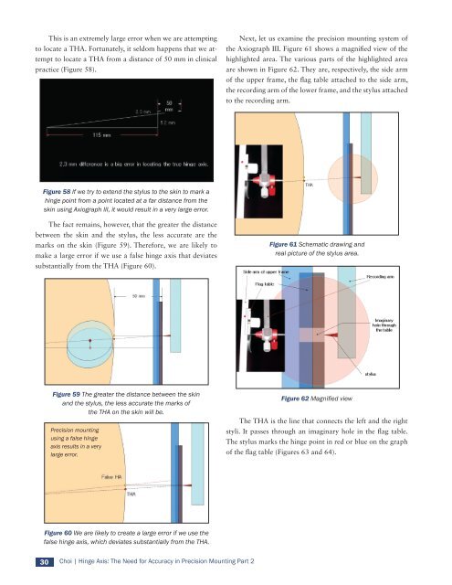
This is an extremely large error when we are attempting<br />
to locate a THA. Fortunately, it seldom happens that we attempt<br />
to locate a THA from a distance <strong>of</strong> 50 mm in clinical<br />
practice (Figure 58).<br />
Figure 58 If we try to extend the stylus to the skin to mark a<br />
hinge point from a point located at a far distance from the<br />
skin using Axiograph III, it would result in a very large error.<br />
The fact remains, however, that the greater the distance<br />
between the skin and the stylus, the less accurate are the<br />
marks on the skin (Figure 59). Therefore, we are likely to<br />
make a large error if we use a false hinge axis that deviates<br />
substantially from the THA (Figure 60).<br />
Figure 59 The greater the distance between the skin<br />
and the stylus, the less accurate the marks <strong>of</strong><br />
the THA on the skin will be.<br />
Precision mounting<br />
using a false hinge<br />
axis results in a very<br />
large error.<br />
Figure 60 We are likely to create a large error if we use the<br />
false hinge axis, which deviates substantially from the THA.<br />
30 Choi | Hinge Axis: The Need for Accuracy in Precision Mounting Part 2<br />
Next, let us examine the precision mounting system <strong>of</strong><br />
the Axiograph III. Figure 61 shows a magnified view <strong>of</strong> the<br />
highlighted area. The various parts <strong>of</strong> the highlighted area<br />
are shown in Figure 62. They are, respectively, the side arm<br />
<strong>of</strong> the upper frame, the flag table attached to the side arm,<br />
the recording arm <strong>of</strong> the lower frame, and the stylus attached<br />
to the recording arm.<br />
Figure 61 Schematic drawing and<br />
real picture <strong>of</strong> the stylus area.<br />
Figure 62 Magnified view<br />
The THA is the line that connects the left and the right<br />
styli. It passes through an imaginary hole in the flag table.<br />
The stylus marks the hinge point in red or blue on the graph<br />
<strong>of</strong> the flag table (Figures 63 and 64).