- Page 2 and 3:
The Haynes Weber Carburetor Manual
- Page 4 and 5:
Contents Introductory pages About t
- Page 7:
0-6 Safety first Regardless of how
- Page 10:
1 2 3 4 I I I I ( Fig . 1.4 The Web
- Page 20 and 21:
Part 1 Introduction Chapter 3 Maint
- Page 24:
Part 1 Introduction Chapter 4 Overh
- Page 27 and 28:
4-4 Part 1 Introduction Chapter 4 F
- Page 29 and 30:
4-6 Part 1 Introduction Chapter 4 F
- Page 31 and 32:
5-2 Part 1 Introduction Chapter 5 2
- Page 34:
5.2 layout of a com plete 44 IOF "P
- Page 37 and 38:
5-8 Part 1 Introduction Chapter 5 5
- Page 40 and 41:
PRECISION MOTORWORKS 930 East Orang
- Page 42:
IntToduetlon The Webe r 28/36 carbu
- Page 46:
5 Disassembly Thoroughly clean the
- Page 49 and 50:
5.2 3b The st art ing air and fuel
- Page 52 and 53:
6 Spec ial overhaul procedures Afte
- Page 55:
6-14 and for t his reason two small
- Page 58 and 59:
Adjustment data M anual choke types
- Page 66 and 67: 3 Disconnect the cho ke plate opera
- Page 70: 5.2 8 Withdrawing the automatic cho
- Page 74 and 75: Fig. 7. ' 7 Location of the cerbuee
- Page 78: 7.66 The main carbur enor body read
- Page 83: 8-0 Part 2 Weber carburetors Chapte
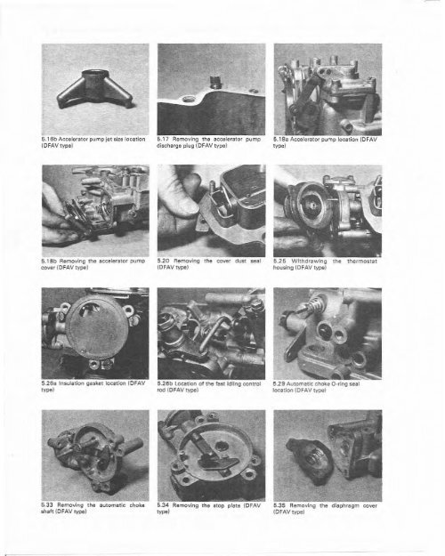
- Page 95 and 96: 8-12 6.20 Accelerator pum p cover l
- Page 97: 8-14 Part 2 Weber carburetors Chapt
- Page 103: 8-20 Part 2 Weber carburetors Chapt
- Page 111 and 112: 9-6 Part 2 Webe r carburetors Chapt
- Page 113: 9-8----
- Page 117 and 118: 9-12 Part 2 Weber carburetors Chapt
- Page 119 and 120: 9-14 ,
- Page 121 and 122: 6.26 Insu lation disc gasket locati
- Page 123 and 124: 9-18 Part 2 Weber carburetors Chapt
- Page 125 and 126: 9-20 Part 2 Weber carburetors Chapt
- Page 128: eturn spring (8 5) in the special h
- Page 132 and 133: Fig. 9.23 Au t omat ic , Choke valv
- Page 134: Adju st ment data Float level setti
- Page 139 and 140: 10-6------------------------ \ " "
- Page 141: 5.10 Electric choke heat insulation
- Page 145: 10-12 Part 2 Weber carburetors Chap
- Page 148 and 149: Du t/pot adjustment (USA typesl 12
- Page 152: The fuel float assembly comprise s
- Page 157 and 158: 0.8 Extracting the float fulcrum pi
- Page 159 and 160: 5.24 Removing a pro gression hole I
- Page 161: 11-12 Part 2 Weber carburet ors Cha
- Page 165:
11-16 Part 2 Weber carburetors Chap
- Page 168:
Part 2 Weber carburetors Chapter 12
- Page 181 and 182:
12-14 Part 2 Weber carburetors Chap
- Page 183 and 184:
13-2 1 Introduction The carburettor
- Page 188:
5.17a Removing the idli ng Jets 5.1
- Page 191:
13-10 Part 2 Weber ca rbu retors Ch
- Page 200 and 201:
9 Special overhaul procedures 1 Ref
- Page 222:
4.2 Removal: Keep Out the fast idle
- Page 227:
17-0 Part 4 SU carburetors Chapter
- Page 231 and 232:
7.1 Removi ng th e f ilter and spri
- Page 233:
17-6 Part 4 SU carburetors Chapter
- Page 236:
Part 4 SU carburetors Chapter 18 Ty
- Page 241:
18-6 Part 4 SU carburetors Chapter
- Page 244:
A Overrun vlillvliI toceuon HS 2. 4
- Page 248 and 249:
7.3/1.. Removing a dampe r fined wi
- Page 251 and 252:
19·8 Part 4 SU carburetors Chapter
- Page 254:
2 Float chamber assembly The float
- Page 258:
is formed. This results in the mixt
- Page 264 and 265:
-> 9.26A Remove the screws (arrowed
- Page 266 and 267:
secure and that the fuel level in t
- Page 268 and 269:
11.24 Ai r valv e location (arrowed
- Page 270 and 271:
13.6 8 Peel the gasket fr om the ca
- Page 273 and 274:
20-20 Part 4 SU carburetors Chapter
- Page 277:
21-4 1 Main bi-m etal unit adjustin
- Page 281 and 282:
21-8 Part 4 SU carbureto rs Chapter
- Page 283 and 284:
6.14A Remove the screws •.. 6.15
- Page 290 and 291:
Part 5 Appendix 2 Conversion equipm
- Page 302 and 303:
M-2 Part 5 Appendix 4 Main me terin
- Page 304:
Main metering "Mdl" fo r .09O jets
- Page 310:
A5-2 Part S Appendix S No.3 Sl!t'i.
- Page 347 and 348:
Part 5 Append ix 8 A8-1 P", Nee dl.
- Page 349:
P.rt N_ dl. P.rt Needle Num ber Mar