Weber Carburator Manual.pdf - Power by BMW E21
Weber Carburator Manual.pdf - Power by BMW E21
Weber Carburator Manual.pdf - Power by BMW E21

You also want an ePaper? Increase the reach of your titles
YUMPU automatically turns print PDFs into web optimized ePapers that Google loves.
7-2<br />
-<br />
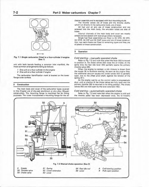
Fig . 7.1 Single carburettor fitted to a four-eylinder V-engine<br />
(Sec 1)<br />
unit with both barrels feeding a common inlet manifold, the<br />
most common arrangements being as fo llows:<br />
1 One unit on a four-c ylinder in-line engine<br />
2 One unit on 8 four-c ylfnder V engine<br />
The ca rburettor iden tificatio n mark is located on the lower<br />
flange outer surface.<br />
2 Construction<br />
The main body and cover of the carburettor ty pes covered<br />
in th is Chapter (Ire of die-cast aluminium or zinc alloy (M azak)<br />
construction. The mounting flange is machine d flat for fitting<br />
purposes. The cover incorporates a mo unting flange for the air<br />
9 Nozzle<br />
35 Throttle valve<br />
50 Choke valve<br />
5 1 Spring<br />
52 Lower extension<br />
53 Lever<br />
Part 2 <strong>Weber</strong> carburetors Chapter 7<br />
cleaner assembl Vand is equipped w it h fou r mounting studs.<br />
The throttle valves are of brass and the th rottl e shafts.<br />
wh ich run directly in the carburettor body, are of steel.<br />
All fuel and air jets are of brass construction and are<br />
screwed into the main body ; the emulsion tubes are also of<br />
brass.<br />
Internal channels of th e main body and cover are mo stly<br />
drilled and are sealed with lead plu gs wh ere necessary.<br />
Single f uel float assemblies are fitted to 32 OFO, 32 OFE.<br />
32 OFM, 32 OIF and 32 OAF types and are of brass constr ucti<br />
on; two semi-f loats are fitted to remaining types and they are<br />
of plastic or brass constr uction .<br />
3 Operation<br />
Fig . 7.2 <strong>Manual</strong> choke operation (Sec3J<br />
Cold starting - manually operated choke<br />
Refer to Fig. 7.2 and note tha t when the lever (53) is moved<br />
to posit ion A, the choke valves (50) close the air intake. At the<br />
same ti me the fast idle lever (55 ) partia lly opens the primary<br />
t hrottl e valve (3 5).<br />
Wh en the engine is cran ked, a rich mixt ure is draw n fro m<br />
the nozzle (9) to facilitate starting. As soon as the engine fires.<br />
the add itio nal vacuum causes t he choke valves (50 ) to partia lly<br />
open , due to the off set pivot shaft , against the tensio n of the<br />
spring (51).<br />
As th e engine w arms up the control cable is pro gressively<br />
shut, until at posit ion B the choke valves are fully open and the<br />
primary throttle (3 5) is returned to its idli ng posit ion. The choke<br />
valves (50) are held open <strong>by</strong> t he lever extension (52 1.<br />
Cold starting - automatically operatedchoke<br />
Refer to Fig. 7.3 and note tha t w hen the engine is cold and<br />
the throttle pedal has been depressed once. the bi-metallic<br />
54 Fast idle rod<br />
55 Lever<br />
52<br />
f..-----'''''4- 54<br />
A Cold starring position<br />
B Fully open position