Weber Carburator Manual.pdf - Power by BMW E21
Weber Carburator Manual.pdf - Power by BMW E21
Weber Carburator Manual.pdf - Power by BMW E21

Create successful ePaper yourself
Turn your PDF publications into a flip-book with our unique Google optimized e-Paper software.
eturn spring (8 5) in the special hole.<br />
3 Fit the bush (26). spring (2 5), washer (22), spring wa sher<br />
(23) and nut (24) to the end of t he throttle shaft (84), then<br />
tight en the nut (84 ) whilst ho lding the shaft stat ionary w ith a<br />
screwdriver insert ed through t he toothed sector.<br />
4 Tension the spring (85) <strong>by</strong> turning th e tooth ed sector, then<br />
insert the th rottle valve into th e throttle shaft (84 ) and close th e<br />
valve. Make sure that the angled perime ter of the valve seats<br />
corr ectly in the barrel and allow it to snap shut several times to<br />
centra lise it.<br />
5 Insert the throttle valve retaining screws (29 } and tighten<br />
t hem evenly but without exert ing excessive pressure on the<br />
shaft . It is recomm ended that new screw s are alwa ys fitted to<br />
avoid crcss-t hreacln q previous ly peened screws. Lock the<br />
screws (2 9) <strong>by</strong> peening with W eber tool no 98010 900 whilst<br />
supporting the shaft with a block of wood. Altematively, coat<br />
the screw th reads with a liquid locking agent (fuel resistant)<br />
prior to inserting them.<br />
6 Insert the Teflon bushes (20 and 2 1) into th e primary<br />
throttle shaft bore of the carburettor body (S6) and light ly<br />
lubricate th em with a little engine oil. Not e that the smaller<br />
bush (2 1) is located at the flo at chamber end.<br />
7 Locate the spacer (30), spring (25) and bush (26) to t he<br />
primary throttle shaft (27 ) w ith the smaller diameter of the<br />
spacer against the accelerator pump operating cam.<br />
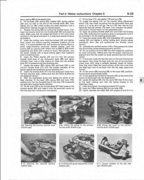
S Insert the throttle shaft (27) into th e carburettor body from<br />
t he float chamber side. making sure th at the Tefl on bushes are<br />
not displaced (photo) .<br />
9 W ith the accelerator pump cam facing the centre of the<br />
float chamber, fit the bush (26 }, spring (2 5) and lever 0 5l.<br />
making sure th at the th readed hole in the lever (75) is towards<br />
t he secondary tooth ed sector (photos) .<br />
10 Fit the bush (76) to the throttle shaft (27) then press on the<br />
toothed secto r (83} and mesh it w it h th e secondary sector so<br />
that th e alignment marks are in line (photo ).<br />
o<br />
9.8 Inserting the primary thro ttle shaft<br />
(DGAS type}<br />
9.10 Aligning th e toothed sectors<br />
(DGAS type)<br />
Part 2 <strong>Weber</strong> carburetors Chapter 9 9-23<br />
9.9a Fittin g the spring to t he primary<br />
throttle shaft (DGAS type)<br />
9.14 Fitting th e sector adjustment screw<br />
(DGA S type}<br />
11 Fit the lever (77L tab w asher {79) and nut (7S}.<br />
12 Locate the spring (74 ) on t he th rottle idling adju stment<br />
screw (7 3), then insert the screw into t he carburettor body and<br />
screw it in as far as it will go. The nut (78) may now be fully<br />
tightened and the Iccktab (79) bent. Fully unscrew the adjustment<br />
screw (73} but leave it in the carburettcr body.<br />
13 Open th e prim ary throttle shaft (27) and insert the throttle<br />
valve (28i, observing the procedure given in paragraphs 4 and 5<br />
to centra lise it. Fit the ret aining screws (29).<br />
14 Insert the sector screw (80) w ith tockw esher (81) and plain<br />
wa sher (82) and tighten it w hilst holding both th rottle valves<br />
compl etely shut ; this will synchronise the throttle valves<br />
(photo).<br />
15 Lubricate the toothed sectors with a little grease and check<br />
that the throttle valves operate smooth ly and fully.<br />
16 Fit the auxili ary veot urls (98) into their respective positi ons<br />
as noted previously, making sure t hat t he supply chann els are<br />
adjacent and th at th e nozzle cut away sections face the thrott le<br />
valves.<br />
17 If removed. locate the fast idle cam on the bush followed <strong>by</strong><br />
the spacer, then press t he bush onto the rear of th e automat ic<br />
choke body (53) using a suita ble diameter length of tubing.<br />
Not e t hat when fitted th e round contour of t he cam must face<br />
the diaphragm end of the body with the flat edge upperm ost<br />
(photo).<br />
18 Fit th e screw (59) and plug (58 } to th e cover (5 6), posit ioning<br />
the screw as previously noted.<br />
19 Fit the operating rod (54) to t he body (53), et th e same time<br />
locate th e diaphragm over the brass dowel.<br />
20 Locate the spring (55) into the cover {56} then fit the cover<br />
to the body making sure that the spring locates in th e<br />
diaphragm plate.<br />
21 Insert and tighten the retaining screws (57) evenly.<br />
22 Insert the Teflon bearing (52) into the body (53).<br />
23 Lightly lubricat e th e shaft l43) w ith engine oil and fit it in<br />
9.9b Fitting th e lever to th e primary<br />
t hrottle shaft (DGAS typ e)<br />
_ 0 _<br />
9.17 Correct location of th e fast idle<br />
cam (DGAS type)<br />
-