Weber Carburator Manual.pdf - Power by BMW E21
Weber Carburator Manual.pdf - Power by BMW E21
Weber Carburator Manual.pdf - Power by BMW E21

Create successful ePaper yourself
Turn your PDF publications into a flip-book with our unique Google optimized e-Paper software.
10-14 Part 2 <strong>Weber</strong> carburetors Chapter 10<br />
79 Fit the retalnlrog ring (18 1and Insert 1M screws (171-<br />
80 Align the merb on tl'le thennost.1 1115Mmbly (19) and<br />
nou sing (2 7) fie centre mark). then ti ght en the reta ining screws<br />
(171-<br />
8 1 Press the li miter cap (6 5) onto the idle mixture screw 1661<br />
w ith the extension pointing away from the main body abut ment.<br />
8 CarblJrettor adjUltmenb<br />
W ith the carburettor com plet ely assemb led. the follow ing<br />
adjustments must be made prior to fitting It to the engine;<br />
, Fully open the throttle. hold the choke valves full y open and<br />
release the t hrottle. Turn the t hrottle idlin g adj ustment screw<br />
(62) unt il it Just tOtJches the idle stop lever (56 ). than continue<br />
to Sa'IW it in 1 complete tum.<br />
2 Tum the idling mixture screw (66) in until it is in light<br />
contact wi th its seat, the n back it off 1 co mple te tum.<br />
3 Tum the secoodary throttle adjustment stop (44) unt il a ga p<br />
of 0 .0 5 mm (O.D02 In) exists between the outer edge of m e<br />
seconda ry throttl e val.... end the secondary berr ei. Check the<br />
liiap w it h fee ler gauge s.<br />
Vacuum pull down<br />
4 Fit an elastic band to the choke lever (14) and over the<br />
cover (11 so t hat it hold s the choke valves (3 1 $hut. Open the<br />
throttl e to allow the choke valves to fu lly close .<br />
5 Using a small electric ian's screw driver, push the cc ntect<br />
ring on th e die phragm spin dle unt il the spindle is in firm contact<br />
with the adjustment screw (24 ). Using a drill o r metal dowel,<br />
check that the dis tance between the choke valve straight edges<br />
and the Intake walls 15 as given in the Adjustment data under<br />
maximum vacuum pull down.<br />
6 To check the minimum vacuum pull down, use long nose<br />
plier s to hold the diaphragm spindle in firm contact w ith the<br />
adj ustment screw 1241.but make sure that the modulato r spring<br />
Is compressed fully. Use a dri ll to make the check in the<br />
identical manner to that given in paragraph 5. Note that on<br />
some carburettor types the minim um vecuu m pull down can be<br />
checked <strong>by</strong> inserting a screwdriver t hrough a hole in the<br />
housing 12 7); on oth er models thilS hol e is blanked off.<br />
7 If any of the dimensions checked in paragraphs 5 and 6 are<br />
not correct, the adjustment screw (24) m ust be turned II<br />
nacessary. This w ill necessit ate removing the seal (25) and the<br />
owner must be satisfied thilt no legislation I, being contravened<br />
<strong>by</strong> thi s action .<br />
Choke phasing<br />
8 Open the th rottle then release it ll nd position the fast idle<br />
adju stin g screw (4 7) on the middle ste p of the fast idle cam.<br />
9 Close the choke valves as fer ll S possibl e <strong>by</strong> turning the<br />
choke lever 1141 antI-clock wi se. Usi ng 8 drill. check th at the<br />
distance between the chok e valve straight edges and the inteke<br />
w alls is as given in the Adjustment deta. If nat. carefu lly bend<br />
the short arm on the shaft 115 1 as neeeeserv li e the int ernal<br />
arm).<br />
Dechoke adjustment<br />
10 Open the throttl e and fully close the choke valves <strong>by</strong> turning<br />
the chOke lever (14) ant i-cloc)(wise. Wh ile holding the lever<br />
IT41. fully open the throttle. The distance between the choke<br />
valve str aight edges and t he intake w ellS should be as give n in<br />
the Adjustment dlta when checked with a suitable drill. If not,<br />
bend the choke lever (2 9) as necessary.<br />
F8st idle adjustment<br />
1 1 Open the throttl e and position the fast idle edjusti ng screw<br />
(4 7) on the highest section of the fast idle cern. Us ing II feeler<br />
gauge. check that the dist ance between the prima ry th rottle<br />
valve and the oute r barrel w all is as given In the Adju stment<br />
data. If not. loosen the locknut (48) end t um the adjusting S(:rew<br />
14 7) as necesmlry: tight en the locknut when the adjustment is<br />
complet ed (pho to).<br />
A<br />
_-_ _ 0<br />
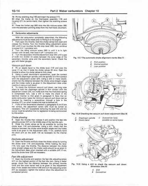
Fig. 10.711M autom.tic ch oke ali gn ment marks (Sec 7 1<br />
A Rich po sition<br />
B Normalposition<br />
C Leim position<br />
Fig, 10.8 Checldng the va cu um pull down adjustment (Sec 81<br />
A Diap hragm spindle<br />
B Elastic btm d<br />
C ScrewdrlvIr (only<br />
possible on some types)<br />
Fig . 10.9 Uaing a drill t o check t he vac uum pull down<br />
dimension (Sec 8 )<br />
A Drill<br />
B Screwdriver