Weber Carburator Manual.pdf - Power by BMW E21
Weber Carburator Manual.pdf - Power by BMW E21
Weber Carburator Manual.pdf - Power by BMW E21

Create successful ePaper yourself
Turn your PDF publications into a flip-book with our unique Google optimized e-Paper software.
11-12 Part 2 <strong>Weber</strong> carburet ors Chapter 11<br />
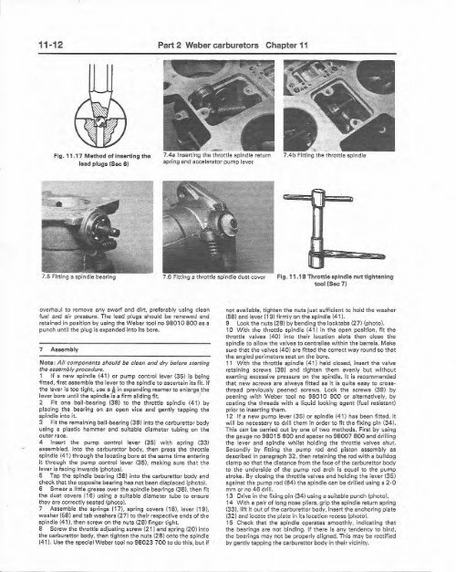
Fig. 11 .17 M ethod of inserting th e<br />
lead plugs (Sec 6 )<br />
-<br />
7.4a Inserting th e th rottle spindle return<br />
spring and accelerato r pump leve r<br />
•<br />
7.4b Fitting th e throttle spindle<br />
7.5 Fitt ing a spi ndle bearin g 7.6 Fitting a throttle spindle dust cover Fig. 11 .18 Thr ottle spindle nut tightening<br />
tool (Sec 7)<br />
overhaul to remove any swarf and dirt, pr eferably using clean<br />
fuel and air pressure. The lead plugs should be renewed and<br />
retained in position <strong>by</strong> using the <strong>Weber</strong> too l no 98 0 10 800 as a<br />
punch until the plug is exp anded into its bore.<br />
7 A ssembly<br />
Not e : All com ponents should be clean and dry before srarting<br />
the assembly procedure.<br />
1 If a new spindle (4 1) or pump control lever (35) is being<br />
fitted, first assemb le the laver to th e spindle to ascertain it s fit . If<br />
th e lever is too tight, use a 11 in expanding reerner to enlarge,the<br />
lever bore unt il the spindle is a fi rm sliding fit.<br />
2 Fit one ball-bearing (38) to t he thro ttle spindle (41) <strong>by</strong><br />
placing the bearing on an open vice and gently tapping the<br />
spindle into it.<br />
3 Fit the remain ing ball-be aring (3 8) into the carburettor body<br />
using a plastic hammer and suitable diameter tub ing on t he<br />
outer race.<br />
4 Insert th e pump contro l lever (3 5) with spring (3 3 )<br />
assembled , into the carburettcr body. then press the throttle<br />
spindle (41) through the locating bore at the same time entering<br />
it th rough the pump contro l lever (3 5). making sure that the<br />
lever is facing inwa rds (photo s).<br />
5 Tap the spindle bearing (38) into the carburettor body and<br />
check that the opposite bearing has not been displaced (photo).<br />
6 Smear a little grease over the spindle bearings (38). then fi t<br />
the dust covers (16) using a suitable diameter tube to ensure<br />
they are correctly seat ed (photo).<br />
7 Assemble the springs (17). spring covers (18), lever (19).<br />
wa sher (58) and tab w ashers (27) to their respecti ve ends of the<br />
spindle (41 ), then screw on the nuts (2 8) finge r tight.<br />
S Screw the throttle adjust ing screw (21 ) and spring (20) into<br />
the carbureltor body, th en tighten the nut s (28 ) onto the spindle<br />
(41). Use the special <strong>Weber</strong> too l no 98023 700 to do thi s. but if<br />
not available, tighten the nuts just suff icient to hold the washer<br />
(58) and lever (19) firmly on the spind le (41).<br />
9 Lock the nuts (28) <strong>by</strong> bending the locktabs (27) (photo).<br />
10 W it h t he throttle spindle (41l in the open posit ion, fit the<br />
throttle valves (40) into t heir location slots then close the<br />
spindle to allow t he valves to centra lise within th e barrels. M ake<br />
sure that the valves (4 0) are fitted the correct w ay round so t hat<br />
t he angled perim eters seat on t he bore.<br />
11 Wit h t he throttle spindle (41) held closed, insert the va lve<br />
retaining screws (39) and tighten them evenly but with out<br />
exerting excessive pressure on th e spindle. It is recommended<br />
that new screws are alwa ys fi tte d as it is quite easy to crossthre<br />
ad previously peened screws. l ock the screw s (3 9) <strong>by</strong><br />
peening w ith <strong>Weber</strong> tool no 98010 900 or alternat ively. <strong>by</strong><br />
coating the th reads with a liquid locking agent (fu el resistant )<br />
prior to insert ing th em.<br />
12 If a new pu mp lever (35) or spind le (41) has been fi tt ed, it<br />
w ill be necessary to drill th em in order to fit the fixin g pin (34).<br />
This can be carried out <strong>by</strong> one of two meth ods. First <strong>by</strong> using<br />
t he gauge no 98015 600 and spacer no 98007 800 and drilling<br />
the lever and spind le whilst holdi ng the throttle valves shut.<br />
Secondly <strong>by</strong> fitting the pum p rod and piston assembl y as<br />
described in paragraph 32 , then retaining the rod w it h a bull dog<br />
clamp so that the distance f rom the face of the carburettor body<br />
to the underside of t he pump rod arch is equal to the pum p<br />
stro ke. By closing the th rottle valves and holding the lever (3 5)<br />
against th e pump rod (54) th e spindle can be drilled using a 2 ·0<br />
mm or no 4 6 drill.<br />
13 Drive in t he fixing pin (3 4) using a suita ble punch (photo).<br />
14 Wi th a pair of long nose plie rs, grip the spindle return spring<br />
(33). lift It out of the cerburettcr body , insert the anchoring plate<br />
(32) and locate the pla te in it s location recess (photo).<br />
15 Check that the spindle operates smoo thly, Indicati ng that<br />
the bearings are not binding. If th ere is any ten dency to bind ,<br />
the bearings may not be properly aligned. This may be recti fied<br />
<strong>by</strong> gent ly tapping th e carb urettor body in t heir vicini ty.