Weber Carburator Manual.pdf - Power by BMW E21
Weber Carburator Manual.pdf - Power by BMW E21
Weber Carburator Manual.pdf - Power by BMW E21

You also want an ePaper? Increase the reach of your titles
YUMPU automatically turns print PDFs into web optimized ePapers that Google loves.
I<br />
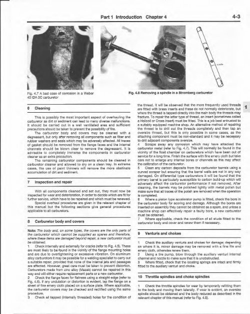
Fig. 4.7 A bad case of corrosion in a <strong>Weber</strong><br />
40 IDA 3C carbureto r<br />
6 Cleaning<br />
Th is is poss ibly t he most important aspect of overhauli ng th e<br />
carburetor as dirt or sediment can lead to many diverse malfunctions.<br />
It should be carried out in a w ell ventil ated area and suff icie nt<br />
precautions should be taken to prevent the poss ibility of fire.<br />
The carbureto r bo dy and covers may be cleaned with a<br />
deqreasant, but only after removing all compo nents such as fiber and<br />
rubber washers and seals which may be adversely affec ted. All traces<br />
of gasket shou ld be removed from th e flange faces and the internal<br />
channels shou ld be blown clear to remove th e dec reasant. It is<br />
advisable to com pletely immerse th e components in carb ureto r<br />
cleaner as an extra precaution.<br />
The remaining carbureto r co mponents shou ld be cleaned in<br />
carbureto r cleaner and allo wed t o dry on a clean t ray. In extreme<br />
ca ses, th e use of pain t thinners w ill remov e th e mor e obsti nat e<br />
accumulation of dirt and sediment.<br />
7 Inspection and repair<br />
Wit h all components cl eaned and set out, th ey must now be<br />
inspected for wear and deterioration, in order to decide which are fit for<br />
furth er service, which have to be repaired and wh ich must be renewed.<br />
Spec ial overhaul procedures are given in the reievant chapter of<br />
this manu al bu t the fo llo wing sect ions give gene ral procedures<br />
app licab le to all carburetors.<br />
8 Carburetor body and covers<br />
Note: The body and. on some types, the covers are the only parts of<br />
the carburetor whic h cannot be supplied as spares and therefore,<br />
where these items are damaged beyond repair, a new carburetor must<br />
be obtained.<br />
1 Chec k internally and externally for cracks (refer to Fig. 4.5). These<br />
are most iikely to be .found in the vicin ity of the flange mounting holes<br />
and are due to overt ightening or excess ive vibrati on. On aluminum<br />
alloy carburetors it may be possible for a welding specialist to carry out<br />
a suitable repair, provided that none of the internal jets and passages<br />
are affec ted . However, great care must be taken to prevent distortion.<br />
Carburetors mad e from zinc alloy (Mazak) cannot be repa ired in t his<br />
way and will either require replaceme nt parts or a new carburetor.<br />
2 Check the flange faces for flatness using a straight-edge (refer to<br />
Fig. 4.6). If any undulation or disto rtion is evident, lap the flange on a<br />
sheet of fine emery cloth placed on a surface plate. Where app licable,<br />
the carburetor covers may be checke d and recti fied using the same<br />
procedure.<br />
3 Check all tapp ed (internaily threaded) holes for th e condition of<br />
Part 1 Introduction Chapter 4<br />
Fig. 4.8 Removing a spindle in a St rombe rg carburetor<br />
4-3<br />
the t hread. It will be obse rved that the more frequently used threads<br />
are fitted with brass inserts and these do not normally deteriorate. but<br />
where the t hread is tapped directly into the main body the threads may<br />
fractu re. To repair the latter type of t hread, an insert (sometimes called<br />
a Helicoil or Cross insert) must be fitted. This is a job best entrusted to<br />
a suitably equipped machine shop . An alternative method of repairing<br />
the t hread is t o dr ill out t he thread s completely and th en ta p an<br />
ov ersize t hread, but thi s is only possible in some cases, as t he<br />
attach ing component must be non-standard and it may be necessary<br />
to drill adjacent components oversize. '<br />
4 Sc rap e awa y any co rros ion wh ich may have attacked the<br />
carburetor meta l (refer to Fig. 4.7). This will normally be found in the<br />
vicinity of the float chamber on carbureto rs which have been out of<br />
service for a long time. Finish the surface with fine emery cloth but take<br />
care not to enlarge any internal bores or channels as this may affect<br />
the calibration of the carburetor.<br />
5 Clean any carbon deposits from t he carburetor barrels using a<br />
curved scraper but ensuring that the barrel walls are not in any way<br />
damaged. On differential ty pe carbu retors it will be fo und that t he<br />
primary barrel is particularly susceptible to carbo n build-up which will<br />
ad versely affect the carb uretor perform ance if not removed. Aft er<br />
clean ing , the barrels may be polished lightly with meta l polish but<br />
make sure that all traces of the polish are removed w hen the op eration<br />
is com pleted.<br />
6 Where a piston type acceierator pump is fitted, check the bore in<br />
the carburetor body for scoring and damage. Although the bores are<br />
inserted on assembly they cannot be obtained as a spare, and unless a<br />
machine shop can effe ctively repair a faulty bore, a new carburetor<br />
must be obtained .<br />
7 Where app licable, check the cond ition of all st uds fitted to the<br />
carburetor body and cover and renew them if necessa ry.<br />
9 Vent uris and chokes<br />
1 Check the auxiliary venturis and chokes for da mage; depending<br />
on w here it is, min or d amag e may be removed w ith a fine file and<br />
emery cloth, ot herwise renew them.<br />
2 Using a t ire pump, b low t hrou gh the aux iliary vent uri internal<br />
channel and nozzle to make sure th at it is unobstructed.<br />
3 Where fitted, check that the iocating springs are intact and firmly<br />
fitted to the auxiliary venturi and choke.<br />
10 Throttle spindles and ch oke spindles<br />
1 Check t he t hrottle spindles for wear <strong>by</strong> tempo rarily relitting them<br />
to the body and moving them laterally. If wear is evident, an oversize<br />
spindle should be obtained and the bod y reduced as described in the<br />
relevant chapter of this manuai (refer to Fig. 4.8).<br />
1