Download PDF - Carl Zeiss
Download PDF - Carl Zeiss
Download PDF - Carl Zeiss

Create successful ePaper yourself
Turn your PDF publications into a flip-book with our unique Google optimized e-Paper software.
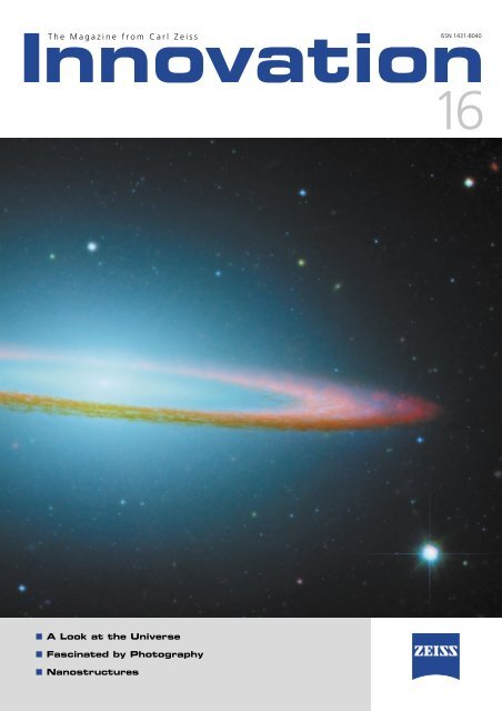
Innovation<br />
The Magazine from <strong>Carl</strong> <strong>Zeiss</strong><br />
■ A Look at the Universe<br />
■ Fascinated by Photography<br />
■ Nanostructures<br />
ISSN 1431-8040<br />
16
Contents<br />
2<br />
Editorial<br />
❚ Dieter Brocksch 3<br />
In Focus<br />
Puzzling Astrophysical Phenomena ❚ Martin Matthias Roth 4<br />
Dark Matter in Spiral Galaxies ❚ Martin Matthias Roth 8<br />
Black Hole in the Holmberg II Galaxy ❚ Martin Matthias Roth 10<br />
Black Holes ❚ Martin Matthias Roth 12<br />
Calar Alto Observatory 13<br />
Celestial Observation 14<br />
Important Historical Developments in the Astrophysics of Potsdam 20<br />
SIR Looks for Ice and Minerals on the Moon ❚ Urs Mall, Chris Weikert 22<br />
The Sun 24<br />
Extrasolar Planet 25<br />
Sun Scout, Weatherman, Comet Hunter 26<br />
Brief History of the Reflecting Telescope 27<br />
The Route to the Stars 28<br />
Planetarium: A Roomful of Universe 32<br />
Observatory Instruments 36<br />
Photography<br />
Fascinated by Photography 37<br />
From Users<br />
Differentiation is the Magic Word 44<br />
Nanostructuring Using 3D Deposition Lithography ❚ Hans W.P. Koops 46<br />
Anniversary<br />
Insights into the Nano World: 40 Years of Scanning Electron Microscopy 50<br />
Prizes and Awards<br />
Fourth Consecutive R&D 100 Award for <strong>Carl</strong> <strong>Zeiss</strong> Microscopy 54<br />
Design Award for ZEISS Victory 32 FL 55 55<br />
Two Awards for the 1540XB CrossBeam ® 55<br />
Company News<br />
<strong>Carl</strong> <strong>Zeiss</strong> SMT AG Acquires NaWoTec GmbH ❚ Hans W.P. Koops 56<br />
Beam Me Up 58<br />
P.A.L.M. Joins the Microscopy Group 59<br />
Masthead 59<br />
Innovation 16, <strong>Carl</strong> <strong>Zeiss</strong> AG, 2005
Dear Readers,<br />
Dive into the world of pictures – pictures from space,<br />
pictures from cities and life on our planet and pictures<br />
from the nano world. Let us fascinate you with images<br />
that deliver factual information as well as tell stories<br />
about the variety of life. Marcel Proust wrote that “the<br />
writer’s work is merely a kind of optical instrument that<br />
makes it possible for the reader to discern what, without<br />
this book, he would perhaps never have seen in himself.”<br />
From the vastness<br />
of the universe<br />
Pictures from space, as difficult as they are to make, give<br />
us an idea of how immense the universe really is. For<br />
centuries, or rather millennia, mankind has been fascinated<br />
and impressed by the beauty of the cosmos. For<br />
thousands of years, we have attempted to interpret and<br />
understand the inner workings of the heavens. Our<br />
knowledge of how and why has been increasing for<br />
hundreds of years. In the beginning, man simply observed<br />
the light from the stars and attributed laws to it.<br />
The first optical instruments provided us with more detailed<br />
images of the stars and also helped us discover<br />
moons and rings. Much of the knowledge from this time<br />
led to a heliocentric view of the universe. Today, we leave<br />
our planet to explore the universe, to explore our origins<br />
and to see the universe up close. Using state-of-the-art<br />
instruments, we analyze the light from the heavens and<br />
get an idea of just how complex the universe actually is.<br />
The more of it we know, the more we are amazed at<br />
how intricate and unfathomable it is.<br />
Innovation 16, <strong>Carl</strong> <strong>Zeiss</strong> AG, 2005<br />
Editorial<br />
Source of information<br />
Important optical advances and inventions have also<br />
paved the way for further developments such as photography.<br />
Since the early days of photography, photographers<br />
have used pictures to tell stories, to deliver information<br />
and to communicate with the observer. Images of<br />
scenes in the cities on our planet offer an insight into<br />
events in our lives, show our organizational structures<br />
and impart a sense of being.<br />
Scanning electron microscopy, still a relatively new<br />
invention, provides fascinating pictures which make it<br />
possible to delve into the details and structures of nature<br />
and the environment. This technology makes structures<br />
and dimensions visible that would otherwise remain<br />
hidden to the human eye.<br />
Sophisticated optical techniques in nano-structuring<br />
help configure electronic circuits for cutting-edge communications<br />
equipment. As a result, modern communications<br />
become faster and more reliable and have a wider<br />
range of use.<br />
Make it visible<br />
True to the company’s motto “We make it visible,” optical<br />
systems from <strong>Carl</strong> <strong>Zeiss</strong> help deliver many new and<br />
sometimes unexpected insights and perspectives. Key optical<br />
technologies use light to recognize new phenomena<br />
and create new products.<br />
Enjoy reading<br />
December 2005<br />
3
In Focus<br />
Puzzling Astrophysical Phenomena<br />
4<br />
Astrophysics is one of the few<br />
disciplines of basic scientific research<br />
which in the foreseeable<br />
future can be expected to deliver<br />
results that will lead to fundamental<br />
alterations in our view of<br />
the physical world comparable to<br />
paradigm changes such as the introduction<br />
of quantum theory or<br />
Einstein’s general theory of relativity<br />
some 100 years ago. Exotic<br />
objects, such as neutron stars,<br />
black holes, remnants of supernovae<br />
and other gas nebulae, as<br />
well as entire stellar systems such<br />
as galaxies and galaxy clusters,<br />
present a unique opportunity to<br />
study matter under extreme tem-<br />
peratures, pressures, densities,<br />
magnetic field strengths and other<br />
physical parameters that cannot<br />
be reproduced in a terrestrial<br />
laboratory. These parameters are<br />
measured in modern astrophysics<br />
using earth-based telescopes as<br />
well as space observatories<br />
which unite to cover the entire<br />
electromagnetic spectrum from<br />
radio waves to x-ray and gamma<br />
radiation.<br />
Focal instruments that allow<br />
the weak light signal gathered by<br />
the telescope to be transformed<br />
into a directly interpretable parameter<br />
are just as important as<br />
the light-gathering power and<br />
resolution of the telescopes employed<br />
in these applications. Direct<br />
imaging cameras, spectrographs<br />
with low, medium or high<br />
spectral resolution, polarimeters,<br />
interferometers and other focal<br />
instruments provide us with a<br />
far-reaching view into the history<br />
of the origin, development and<br />
structure of physical phenomena<br />
– some of which are not yet understood.<br />
Consequently, the use<br />
of state-of-the-art technology in<br />
modern telescopes has become<br />
an indispensable element in modern<br />
astrophysical research.<br />
Innovation 16, <strong>Carl</strong> <strong>Zeiss</strong> AG, 2005
3D spectroscopy – a<br />
new measuring procedure<br />
in astrophysics<br />
Since its reestablishment in 1992, the<br />
Astrophysics Institute in Potsdam<br />
(AIP) – one of the first observatories<br />
in Germany – has been advancing<br />
the targeted establishment of infrastructure<br />
for the development of<br />
modern astronomical telescopes and<br />
focal instruments in addition to its<br />
traditional fields which include stellar<br />
physics, extragalactics and cosmology.<br />
The first specific project in this<br />
area began in 1996 with the development<br />
of the PMAS (Potsdam Multi-<br />
Aperture Spectrophotometer), an innovative<br />
imaging spectrograph (Fig.<br />
1). This new technique is often<br />
referred to as integral field spectroscopy<br />
or 3D spectroscopy for<br />
short. Its measuring principle is illustrated<br />
in Fig. 2: the real image of<br />
an object, e.g. a galaxy, generated in<br />
the focal plane of the telescope is<br />
scanned using a lens scanner, with<br />
the scanner's finite number of m x n<br />
lens elements transforming the im-<br />
Innovation 16, <strong>Carl</strong> <strong>Zeiss</strong> AG, 2005<br />
age into a discrete number of m x n<br />
image elements. The light impinging<br />
on each image element is coupled<br />
from the focal plane by a dedicated<br />
fiber of a light guide bundle and<br />
transmitted to a more or less remote<br />
fiber spectrograph.<br />
By rearranging the rectangular image<br />
elements into a linear fiber array<br />
in the entry plane of the spectrograph<br />
it is very easily possible to<br />
adapt the geometry of the 2-dimensional<br />
object to the linear structure of<br />
the spectrograph slit. Each fiber is<br />
thus imaged individually by the spectrograph<br />
optics in the form of a small<br />
circle onto the CCD detector, whereby<br />
the dispersion of the diffraction<br />
grating pulls the fiber image apart to<br />
form a band of light when illuminated<br />
with a continuum; alternatively, a<br />
number of discrete points of light<br />
along this band is seen when illuminated<br />
with a spectrum of emission<br />
lines (Fig. 3). This generates a family<br />
of (m x n) spectra on the detector<br />
which can be extracted, calibrated<br />
and then combined for image reconstruction<br />
using suitable software<br />
after the image has been scanned into<br />
the computer. The result of this<br />
type of image reconstruction is called<br />
a data cube – hence the term 3D<br />
spectroscopy (Fig. 4). Depending on<br />
the view, the data cube can be interpreted<br />
as a stack of monochromatic<br />
image recordings or as a bundle of<br />
individual spectra in a rectangular<br />
array. This procedure has obvious<br />
advantages: 3D spectroscopy is a fully<br />
simultaneous measuring procedure in<br />
which the entire data set is recorded<br />
in a single exposure. As the light intensity<br />
of the majority of objects of<br />
interest in astrophysics is extremely<br />
weak and requires the use of expensive<br />
large telescopes, this aspect<br />
is becoming increasingly important,<br />
particularly for the most interesting<br />
current topics.<br />
Fig. 1:<br />
PMAS (Potsdam Multi-<br />
Aperture Spectrophotometer)<br />
at the Cassegrain focus<br />
of the <strong>Carl</strong> <strong>Zeiss</strong> 3.5 m<br />
reflecting telescope at<br />
Calar Alto Observatory<br />
in southern Spain.<br />
Fig. 2:<br />
Design principles of an<br />
integral field spectrograph<br />
with lens array and fiber<br />
coupling.<br />
Fig. 3:<br />
Part of a PMAS<br />
calibration image taken<br />
with continuous light<br />
(continuous strips) and<br />
emission line spectrum<br />
(printed points).<br />
The partial image shows<br />
two groups of 16 spectra<br />
each; the direction of<br />
dispersion is from left to<br />
right.<br />
1 2<br />
3<br />
5
Fig. 4:<br />
Schematic representation<br />
of a data cube<br />
which can be generated by<br />
rearranging the spectra<br />
extracted from the CCD<br />
image: this results in a<br />
cube with two positional<br />
coordinates and one<br />
wavelength coordinate.<br />
The cube can be seen as<br />
a stack of images across the<br />
field of view scanned in<br />
the lens array with exposure<br />
of all these images at<br />
different wavelengths.<br />
Fig. 5:<br />
Sectional view showing the<br />
PMAS spectrograph optics<br />
(bottom: overall system in<br />
the dispersion plane defined<br />
by the collimator axis and<br />
camera axis; top: collimator<br />
lens in a sectional view<br />
perpendicular to this<br />
plane).<br />
6<br />
The Potsdam<br />
Multi-Aperture<br />
Spectrophotometer<br />
The concept of the first AIP instrumentation<br />
project kicked off an ambitious<br />
project aimed at nothing less<br />
than the construction of the most<br />
powerful 3D spectrograph in the<br />
world for the near UV (350 nm) to<br />
the near IR (1000 nm). This is the<br />
spectral window in which the atmosphere<br />
is translucent for ground-based<br />
observations. The project was also intended<br />
to develop optimal sensitivity,<br />
rendering the instrument competitive<br />
for observation of even the weakest<br />
sources. Only high-performance optics<br />
were acceptable for the optical<br />
system (see box for requirements).<br />
<strong>Carl</strong> <strong>Zeiss</strong> was our most important<br />
partner during the development of<br />
the optics for the PMAS fiber spectrograph<br />
which dominate the overall<br />
behavior of the instrument as the<br />
central and most important optical<br />
component. Uwe Laux from Weimar,<br />
Germany designed the optics of the<br />
fiber spectrograph (Fig. 5). The initial<br />
design was based on the assumption<br />
of catalog data such as refractive<br />
index and lens radius. Three rounds<br />
of optimization were performed over<br />
the course of material acquisition,<br />
fabrication, and integration of the<br />
system. Following acquisition of the<br />
optical glasses supplied by SCHOTT,<br />
melt refractive indices determined individually<br />
for each blank were used<br />
to perform a melt calculation. Finally,<br />
after production and testing of the<br />
individual lenses, the actual measured<br />
radii and thickness values were<br />
used to carry out a third optimization<br />
procedure in which the critical system<br />
parameters were set to optimal<br />
values by adapting the back focal<br />
distances, i.e. by a process of mechanical<br />
re-optimization.<br />
The planned use on the telescope<br />
tightened the requirements on the<br />
PMAS even further. It was essential<br />
to maintain the specified image<br />
stability in any geometric orientation<br />
(telescope rotation) and over an extremely<br />
broad range of temperatures<br />
(--20° to +20° C). The system ultimately<br />
produced and completely<br />
integrated by <strong>Carl</strong> <strong>Zeiss</strong> consists of a<br />
refractive collimator and a refractive<br />
camera lens. In particular, the project<br />
benefited from the years of experi-<br />
1<br />
2<br />
ence in the construction of apochromatic<br />
lenses for astronomical refractor<br />
objectives, as well as the knowhow<br />
in the production of aspherical<br />
lenses and lithographic CaF 2 lenses.<br />
Following an extensive series of<br />
tests (Fig. 6, 7), a one-of-a-kind<br />
system was delivered in 1999. The<br />
development of PMAS provides a<br />
critical component with excellent<br />
performance characteristics.<br />
Use at Calar Alto<br />
observatory<br />
The PMAS was used for the first time<br />
in May 2001 on the 3.5 m telescope<br />
at the Calar Alto observatory (Fig. 8).<br />
Developed 30 years ago by <strong>Carl</strong> <strong>Zeiss</strong>,<br />
this telescope continues to embody<br />
a significant technological step. It<br />
was the first application of the<br />
ZERODUR glass ceramics that had<br />
been specially developed by Schott<br />
for astronomy – a classic example of<br />
a successful transfer of technology<br />
from basic scientific research.<br />
The PMAS has been available to<br />
German and Spanish astronomers<br />
since the fall of 2002 as a generally<br />
accessible user instrument based on a<br />
17<br />
18<br />
3 4 5 6 7 8 9<br />
16 15 14 13 12 11 10<br />
4 5<br />
Innovation 16, <strong>Carl</strong> <strong>Zeiss</strong> AG, 2005
contractual relationship between the<br />
Max Planck Institute of Astronomy in<br />
Heidelberg, Germany and the Astrophysics<br />
Institute in Potsdam. After<br />
three years of operation, the PMAS<br />
has become the second-most requested<br />
focal instrument at the<br />
3.5 m telescope and proven its<br />
reliability in more than 150 night sessions<br />
over the course of a total of<br />
45 observation campaigns. The instrument<br />
has been used to address<br />
a wide variety of scientific questions,<br />
e.g. the observation of jets in young<br />
stars, the surroundings of hot, luminous<br />
stars, galactic planetary nebulae,<br />
stellar populations in close-by<br />
galaxies, kinematics of highly redshifted<br />
galaxies, active galaxy cores,<br />
gravitational lenses and many others.<br />
Martin Matthias Roth,<br />
Astrophysics Institute Potsdam<br />
http://www.aip.de<br />
Innovation 16, <strong>Carl</strong> <strong>Zeiss</strong> AG, 2005<br />
6<br />
7<br />
special<br />
Requirements<br />
for PMAS<br />
spectrograph optics<br />
� Nominal temperature 20 °C<br />
� Range of operating temperatures<br />
--10 … +20 °C<br />
� Range of storage temperatures<br />
--25 … +50 °C<br />
� Up to 95% relative humidity<br />
� Shock resistance: up to 10 g,<br />
dynamic: up to 2 g<br />
(0.5 --100 Hz)<br />
� Orientation: nominal operation<br />
at any orientation<br />
� Nominal range of wavelengths:<br />
350-900 nm<br />
� Image quality: image diameter<br />
typically 15 µ at 80% energy<br />
focusing<br />
� Antireflection layers: broad-band<br />
antireflection coated 350-900<br />
nm, mean of max. 1% residual<br />
reflection<br />
� Thermally compensated<br />
mechanical mounts<br />
� Joining technology: free of<br />
tension due to oil immersion<br />
8<br />
Fig. 6:<br />
Collimator lens during<br />
acceptance testing at the<br />
Jena factory.<br />
Fig. 7:<br />
Overall system during the<br />
acceptance test for<br />
verification of the positional<br />
stability of the image at<br />
varying orientations.<br />
Fig. 8:<br />
Overall view of the <strong>Carl</strong><br />
<strong>Zeiss</strong> 3.5 m reflecting<br />
telescope with the PMAS<br />
in Cassegrain focus.<br />
7
Dark Matter in Spiral Galaxies<br />
Fig. 1:<br />
PPAK fiber bundle IFU.<br />
Fig. 2:<br />
PPAK fiber bundle with six<br />
small auxiliary bundles for<br />
measuring the brightness of<br />
the celestial background.<br />
Fig. 3:<br />
View of spiral galaxy<br />
UGC463 (right) reconstructed<br />
from a PPAK<br />
recording compared to a<br />
direct image taken with the<br />
Palomar Schmidt telescope<br />
(left). The PPAK-IFU<br />
provides the PMAS with<br />
the largest field of view<br />
of any 3D spectrograph in<br />
the world.<br />
8<br />
One of the most interesting and<br />
burning topics in astrophysics is<br />
the unsolved mystery of dark<br />
matter. Observation results show<br />
that approx. 90% of the matter in<br />
space exists in the form of socalled<br />
dark matter. Although this<br />
major component of the universe<br />
is not luminous and therefore<br />
inaccessible to direct observation,<br />
it can be inferred indirectly,<br />
e.g. by observing rotation curves<br />
of remote galaxies. Theoretical<br />
astrophysicists at AIP are using<br />
state-of-the-art supercomputers<br />
to develop numerical simulation<br />
calculations to describe the formation<br />
of structures in the universe<br />
in which the existence of<br />
dark matter provides a crucial<br />
foundation. For observations, the<br />
PMAS team collaborates with M.<br />
Verheijen (Groningen, Netherlands)<br />
and M. Bershady (Wisconsin,<br />
USA) to carry out measurements<br />
aimed at determining the<br />
distribution of dark matter in<br />
and around individual galaxies.<br />
These investigations focus on the<br />
nearby so-called “face-on” spiral<br />
galaxies whose disc structure is<br />
fully visible in a perpendicular top<br />
view. These very easy to see<br />
objects will be used to investigate<br />
the exact distribution of dark<br />
matter within the disc and out<br />
into the halo surrounding the<br />
galaxy.<br />
1<br />
2<br />
The presence of dark matter is felt<br />
by its gravitational effect on the dynamic<br />
behavior of the approx. one<br />
hundred billion stars orbiting the<br />
center of the galaxy. Spectroscopy of<br />
the light of stars and the study of<br />
the Doppler effect can be used to<br />
measure the kinematics of a galaxy.<br />
However, most galaxies outside the<br />
Milky Way are so remote that the<br />
stars cannot be seen individually.<br />
They instead blur into a diffuse luminous<br />
distribution of light.<br />
Spectroscopy of<br />
large plane sources<br />
3D spectroscopy appears to be ideally<br />
suited for the spectroscopy of large<br />
plane sources. It offers two significant<br />
advantages over conventional<br />
methods: first, several hundred spectra<br />
can be recorded simultaneously in<br />
a two-dimensional field of view.<br />
Thus, there is no need for time-consuming<br />
and costly sequential scanning<br />
in the study of large-scale objects,<br />
such as the “face-on” galaxies<br />
to be investigated. Each image point<br />
of the observed two-dimensional<br />
field of view yields its own spectrum,<br />
i.e. the light of each and every point<br />
of the galaxy is analyzed by wavelength.<br />
In this fashion, the spectral<br />
information is recorded directly as a<br />
function of its spatial distribution<br />
which is key to measuring dark matter.<br />
Second, digital image processing<br />
methods allow inclusion of minute<br />
luminous sources on the edge of<br />
galaxies in the analysis. Previously,<br />
not even the world's largest telescopes<br />
equipped with the most sensitive<br />
instruments were capable of<br />
solving this observation problem. The<br />
high sensitivity of the PMAS and the<br />
application of 3D spectroscopy promised<br />
to provide a breakthrough in observation<br />
technology addressing this<br />
problem.<br />
Innovation 16, <strong>Carl</strong> <strong>Zeiss</strong> AG, 2005
Dec. (2000)<br />
21’<br />
40’’<br />
14°, 20’, 20’’<br />
20’<br />
Innovative upgrade<br />
of PMAS<br />
However, the field of view of the<br />
instrument was initially optimized for<br />
the study of small-scale phenomena<br />
and thus was too small to detect<br />
entire galaxies in a single exposure.<br />
For this reason, the PMAS was enhanced<br />
with a technical innovation<br />
that enables the instrument to cover<br />
the entire field of view required for<br />
large disc galaxies. Within a record<br />
time of only about half a year, a new<br />
integral field unit (IFU) consisting of<br />
a new, larger glass fiber bundle and<br />
upstream lens optics was developed<br />
at AIP: PPAK (PMAS fiber PacK,<br />
Fig. 1). This unit started operation in<br />
2004. PPAK consists of 331 densely<br />
packed optical glass fibers, each of<br />
which observes one image point with<br />
a diameter of 2.7 arc seconds in the<br />
sky. Six additional glass fiber bundles<br />
are used to measure the background<br />
radiation of the night sky and 15<br />
more fibers are used for wavelength<br />
calibration of the scientific data. In<br />
particular, the microscopic arrangement<br />
of the 400 fibers in a minute<br />
space, i.e. a 5 x 5mm hexagon, presented<br />
a major technical challenge<br />
Innovation 16, <strong>Carl</strong> <strong>Zeiss</strong> AG, 2005<br />
UGC 463<br />
POSS-II PPak reconstruction<br />
349 309 0h ,43m ,329 R.A. (2000)<br />
Dec. (2000)<br />
21’<br />
40’’<br />
14°, 20’, 20’’<br />
20’<br />
349 309 0h ,43m ,329 R.A. (2000)<br />
to the developers at AIP (Fig. 2). Its<br />
field of view of 74 x 65 arc seconds –<br />
this corresponds to approx. 0.2 percent<br />
of the area covered by the full<br />
moon – makes PPAK the largest 3D<br />
spectrograph in the world capable<br />
of scanning contiguous large-scale<br />
objects in the universe.<br />
The first scientific image recorded<br />
with the new PPAK-IFU (Fig. 3) shows<br />
the UGC463 galaxy (right) with excellent<br />
consistency to a direct image<br />
recording from the Palomar image<br />
atlas (POSS) used as a reference.<br />
Martin Matthias Roth,<br />
Astrophysics Institute Potsdam<br />
http://www.aip.de<br />
3<br />
special<br />
Instruments for astronomical<br />
observation and calculations<br />
Astrolabe<br />
The astrolabe is an instrument for angle measurement<br />
in the sky.<br />
Armillary sphere<br />
An armillary sphere (from Latin armillaris – ring/bracelet)<br />
is an astronomical instrument used either to measure<br />
coordinates in the sky or to represent the motion of<br />
celestial bodies.<br />
Mural quadrant<br />
A historical astronomical instrument used to determine<br />
the heights and positions of stars. The mural quadrant<br />
consists of a 90° arc with a divided scale, a reading<br />
device, a sight and a plumb bob. The star to be determined<br />
is sighted, and the position of the plumb bob<br />
suspended from the 90° arc indicates the height angle.<br />
Jacob’s staff<br />
Jacob's staff (Latin: baculus jacob), or cross staff, is an<br />
early astronomical instrument used to measure angles.<br />
It was mainly used in nautical travel and is considered<br />
to be the functional predecessor of the sextant.<br />
Clepsydra (water clock)<br />
For thousands of years, clepsydras were used as time<br />
measuring apparatuses which, unlike sundials, were<br />
independent of the time of day and weather conditions.<br />
Sundial<br />
As astronomical instruments, sundials use the sun’s<br />
position in the sky to approximately indicate the time<br />
of day.<br />
Ring sundial<br />
A portable sundial with an accuracy of five minutes.<br />
9
Black Hole in the Holmberg II Galaxy<br />
Fig. 1 (large figure):<br />
The Holmberg II dwarf<br />
galaxy (Palomar image)<br />
Fig. 2:<br />
Positional charts of the<br />
x-ray recordings of<br />
Ho II-X1 as an overlay over<br />
an image of the visual<br />
spectral range (false-color<br />
image). The high excitation<br />
nebula surrounding the<br />
black hole proven to exist<br />
by PMAS is indicated by<br />
a black circle.<br />
10<br />
Galaxies are clusters of stellar systems<br />
outside the Milky Way that<br />
occur in two main forms. Elliptic<br />
galaxies have a homogeneous,<br />
triaxial structure and a uniform<br />
stellar population. Spiral galaxies<br />
have a spiral structure and differential<br />
rotation, the spiral arms<br />
being the centers of star formation.<br />
Our closest neighbor, the<br />
Andromeda Nebula (M 31, NGC<br />
224), is a spiral galaxy of type Sb<br />
in the Andromeda constellation.<br />
Galaxies are separated from each<br />
other by immense, largely empty<br />
space. At a rough estimate, more<br />
than 50 billion galaxies can theoretically<br />
be observed from the<br />
earth using state-of-the-art technology.<br />
It is estimated that an<br />
average galaxy consists of some<br />
100 billion stars.<br />
Innovation 16, <strong>Carl</strong> <strong>Zeiss</strong> AG, 2005<br />
2
The brightest object in the class of<br />
ultra-luminous x-ray sources (ULX) in<br />
the local group, i.e. the cluster of<br />
galaxies closest to the Milky Way, is<br />
situated in the Holmberg II dwarf<br />
galaxy approx. 10 million light-years<br />
away (Fig. 1). In addition to investigations<br />
in the x-ray range, the search<br />
for emissions in the visual range of<br />
the spectrum is of key interest. It<br />
is hoped that spectral analysis of<br />
this radiation may allow scientists to<br />
make a conclusion regarding the<br />
nature of accretion and the mass of<br />
the object.<br />
During the PMAS Science Verification<br />
Run at the Calar Alto 3.5 m telescope,<br />
Ho II-X1 was observed which<br />
indeed demonstrated the extremely<br />
faint signature of a high-excitation<br />
gas nebula at the site of the x-ray<br />
source (Fig. 2). Earlier observations<br />
with an elongated slit spectrograph<br />
had been unsuccessful as the uncertain<br />
positional information from the<br />
x-ray data made a “coincidental” hit<br />
in directing the telescope very unlikely.<br />
The 8x8 arc second field of view<br />
of the PMAS made it possible to<br />
direct the telescope without having<br />
to make presumptions regarding the<br />
suspected coordinates so that the<br />
Innovation 16, <strong>Carl</strong> <strong>Zeiss</strong> AG, 2005<br />
high excitation helium II emission line<br />
at 486.6 nm, as an indicator, appeared<br />
just on the edge of the field<br />
of view. The analysis of the dimensions<br />
of the object and its kinematic<br />
properties together with the x-ray<br />
observation data indeed showed<br />
that Ho II-X1 is highly likely to be<br />
an intermediate-size black hole. The<br />
results obtained by the international<br />
research group of Lehmann (Max<br />
Planck Institute of Extraterrestrial<br />
Physics, Garching, Germany) and the<br />
PMAS team (AIP) were published as<br />
the cover story in the March 2005<br />
issue of the renowned technical<br />
journal, Astronomy & Astrophysics.<br />
Fig. 3a: Top: Monochromatic images<br />
at various important wavelengths<br />
extracted from the data cube<br />
of a PMAS recording. Bottom: Velocity<br />
field (false-color chart) and width<br />
at half intensity of the emission lines<br />
of hydrogen at 486.1 nm (H-beta)<br />
and oxygen at 500.7 nm ([O III]). A<br />
red circle at the lower left marks the<br />
point at which the high excitation<br />
helium emission line was detected.<br />
Fig. 3b: The spectrum generated<br />
by addition within the red circle (Fig.<br />
3a). The weak emission line indicated<br />
by He II (singly-ionized helium) shows<br />
f � (1E-15)<br />
5<br />
4<br />
3<br />
2<br />
1<br />
HE II<br />
H-beta<br />
that a compact, extremely hot source<br />
resides in this area. The same line is<br />
not detectable in other regions.<br />
Fig. 3c: Actual observation of a<br />
gravitational lens, in which a lowluminosity<br />
galaxy in the foreground<br />
(faint red spot in the center), rather<br />
than a black hole, splits the light of<br />
a far-away bright quasar behind the<br />
galaxy in the foreground into 4 components<br />
(PMAS observation). Quasars<br />
are enormously bright, active galaxy<br />
cores, in which accretion towards<br />
a super mass-rich black hole gives<br />
rise to luminosity exceeding the total<br />
brightness of the galaxy by far.<br />
[0 III]<br />
[0 III]<br />
Martin Matthias Roth,<br />
Astrophysics Institute Potsdam<br />
http://www.aip.de<br />
0<br />
4600 4800<br />
� (Å)<br />
5000<br />
3a 3b<br />
3c<br />
11
Black Holes<br />
12<br />
Black holes were predicted as<br />
mathematical singularities by the<br />
general theory of relativity from<br />
Albert Einstein. However, it is<br />
said that Einstein never believed<br />
in the real existence of such objects.<br />
In 1916 during World War I,<br />
the former director of the Astrophysical<br />
Observatory in Potsdam,<br />
Karl Schwarzschild, proposed a<br />
solution to Einstein’s field equations<br />
for the case of a mass united<br />
in a point of no dimensions:<br />
a so-called black hole.<br />
Popular scientific interests and science<br />
fiction literature have brought<br />
the property of an event horizon to<br />
the attention of a larger audience.<br />
Predicted by Schwarzschild, the event<br />
horizon is the point beyond which no<br />
matter or radiation can escape from<br />
the gravitation pull of a black hole.<br />
Meanwhile, numerous astrophysical<br />
measurements have more or less<br />
proven the existence of black holes.<br />
Although this type of object cannot<br />
be seen by definition, the effects of<br />
a black hole on its surroundings can<br />
be used to deduce its existence, for<br />
example from the observed orbital<br />
movement of stars in the immediate<br />
vicinity of this singularity.<br />
Black holes draw attention to<br />
themselves in a spectacular way<br />
through the inflow of mass (accretion)<br />
leading to the formation of an<br />
accretion disc in which all matter unstoppably<br />
spirals towards the event<br />
horizon and heats up to extreme<br />
temperatures in the process. The ensuing<br />
emission of energy from the<br />
plasma that has reached a temperature<br />
of millions of Kelvin is particularly<br />
intensive in the x-ray range. Mainly<br />
from observations with the ROSAT<br />
space telescope, astronomers know<br />
that the universe is full of super<br />
mass-rich black holes residing in<br />
the center of galaxies. Today, it is<br />
believed that basically all galaxies the<br />
size of Milky Way harbor a black<br />
hole in their center, typically with a<br />
mass of several million times that of<br />
the sun. ROSAT observations also<br />
revealed the existence of so-called<br />
ultra-luminous x-ray sources (ULX)<br />
whose x-ray luminosity is several<br />
million-fold larger than the total<br />
luminosity of the sun. These do not<br />
reside in the dynamic center of<br />
galaxies, but mainly in regions with<br />
ongoing star formation or relatively<br />
young stars. In contrast to super<br />
mass-rich black holes, which accumulated<br />
their immense mass by accretion,<br />
these structures are thought<br />
to be black holes in a medium<br />
mass range of up to approx. 100-fold<br />
the mass of the sun. Only very few<br />
candidates are known at this time.<br />
Martin Matthias Roth,<br />
Astrophysics Institute Potsdam<br />
http://www.aip.de<br />
Innovation 16, <strong>Carl</strong> <strong>Zeiss</strong> AG, 2005
Calar Alto Observatory<br />
The German-Spanish Astronomical<br />
Center/Centro Astronómico<br />
Hispano-Alemán (DSAZ/CAHA) is<br />
an observatory located on the<br />
2168 m high Calar Alto mountain<br />
in the Sierra de los Filabres in<br />
southern Spain.<br />
Innovation 16, <strong>Carl</strong> <strong>Zeiss</strong> AG, 2005<br />
2130<br />
N<br />
2120<br />
2100<br />
to Almeria<br />
2110<br />
Service-<br />
Building<br />
2100<br />
Appartments<br />
2120<br />
2140<br />
Hotel<br />
The Spanish king Juan <strong>Carl</strong>os I<br />
opened the Calar Alto observatory in<br />
September 1979. Over the last 25<br />
years, the telescopes (1.23 m, 2.2 m<br />
and 3.5 m) were primarily available<br />
to German and Spanish astronomers.<br />
Since January 1, 2005, the Calar Alto<br />
observatory has been jointly operated<br />
on an equal basis by the Max Planck<br />
Society and the Spanish Consejo Superior<br />
de Investigaciones Científicas<br />
(CSIC).<br />
The PMAS (Potsdam Multi-Aperture<br />
Spectrophotometer) of the Potsdam<br />
Astrophysics Institute is installed<br />
on the 3.5 m telescope.<br />
Institute<br />
Powerplant<br />
Dormitories<br />
2110<br />
2120<br />
www.mpia.de/Public/<br />
2160<br />
Spanish<br />
1.5 m-Telescope<br />
Schmidt-<br />
Telescope<br />
2150<br />
0 100 200 300 m<br />
2140<br />
2150<br />
2160<br />
1.23 m-<br />
Telescope 2.2 m-Telescope<br />
3.5 m-Telescope<br />
2140<br />
2120<br />
Fig. 1:<br />
Dome where the<br />
3.5 m telescope is housed.<br />
Fig. 2:<br />
3.5 m telescope.<br />
0<br />
0<br />
2100<br />
13<br />
2090
Celestial Observation<br />
14<br />
From the beginning of time, human<br />
beings have been fascinated<br />
by the heavens. It began with the<br />
first visual observations of the<br />
night sky and the description of<br />
the path of the sun and stars<br />
across the sky. Systematic observations<br />
of the sky began in the<br />
third millenium B. C. Thus, astronomy<br />
is the oldest of the sciences.<br />
Many astronomical observations<br />
were a result of astrological interests.<br />
Virtually all cultures regard<br />
the sky and its phenomena as<br />
signs of a higher power or godlike<br />
force. That the thinkers of the<br />
ancient world saw astronomy and<br />
astrology as one and the same<br />
Famous astr<br />
Anaximander (approx. 611-546 B. C.)<br />
The first person to propose a cosmogony<br />
based purely on physics:<br />
a history of origins founded entirely on<br />
observation and rational thinking.<br />
He was also the first to see the cosmos<br />
as a systematically structured whole.<br />
Anaximander designed the first map of<br />
the earth and is said to have constructed<br />
the first celestial globe.<br />
is evident from the names they<br />
gave the constellations of the<br />
northern hemisphere and our<br />
galaxy, the Milky Way. Many of<br />
these are derived from Greek<br />
mythology or history. Early on,<br />
the stars served as important<br />
landmarks for nautical travel and<br />
the division of the year by means<br />
of calendars. The exact point in<br />
time at which the history of<br />
astronomy truly began cannot be<br />
determined conclusively as many<br />
of the ancient documents were<br />
irretrievably lost when the library<br />
of Alexandria was destroyed numerous<br />
times.<br />
Innovation 16, <strong>Carl</strong> <strong>Zeiss</strong> AG, 2005
onomers<br />
Aristarchus of Samos<br />
(approx. 310-230 B. C.)<br />
One of the first proponents of the heliocentric<br />
model of the solar system.<br />
His studies of the interaction between the<br />
sun and earth built on Epicure’s and<br />
Democrit’s views of the world's infinity.<br />
Having reached the conclusion that the<br />
earth revolves around the sun, he broke<br />
with the notion that the earth is at the<br />
center of the universe. His ideas were<br />
taken up again centuries later.<br />
The steady improvements of observation<br />
devices allowed astronomers to<br />
gain more and more insights. The<br />
discoverers continuously expanded<br />
their knowledge in areas such as the<br />
planets of our solar system, remote<br />
galaxies, other celestial bodies, the<br />
physical laws governing the universe,<br />
the development of stars and of the<br />
entire universe. The telescope was<br />
invented some 400 years ago. Galileo<br />
Galilei, among others, used it<br />
for astronomical observations. Major<br />
strides in astronomical research were<br />
made during the 19 th century by<br />
integrating photography and spectroscopy.<br />
Manned and unmanned<br />
space missions provided new means<br />
of observation and research beginning<br />
at the middle of the 20 th century.<br />
To date, a broad range of physical<br />
measuring technologies is used to<br />
observe all forms of electromagnetic<br />
or particle radiation originating in<br />
space: astrophysics provides the<br />
physical foundations for researching<br />
the celestial phenomena.<br />
Innovation 16, <strong>Carl</strong> <strong>Zeiss</strong> AG, 2005<br />
Ptolemy, Greek: Klaudios Ptolemaios,<br />
Latin: Claudius Ptolemaeus (87-150 B. C.)<br />
Assumed to have lived and worked in<br />
Alexandria. He wrote the Mathematike<br />
Syntaxis and later the Megiste Syntaxis,<br />
a treatise on mathematics and astronomy.<br />
Today, it is known as Almagest and considered<br />
to be the definitive work on astronmy<br />
in the Middle Ages. In addition to a star<br />
catalog, it contained the geocentric<br />
cosmology proposed by Hipparchus of<br />
Nicea, also termed the Ptolemaic system.<br />
Prehistoric<br />
observations<br />
Prehistoric astronomical observations<br />
were conducted as early as the<br />
Bronze Age, at least in the form of<br />
simple celestial observations. The disc<br />
of Nebra is evidence of early astronomy.<br />
Megalithic structures of the<br />
Bronze Age such as Stonehenge<br />
which consists of several concentric<br />
circles of rocks also demonstrate early<br />
efforts to observe the stars. The<br />
oldest evidence in Stonehenge dates<br />
back to the year 3100 B.C. Since the<br />
rocks are aligned according to the<br />
positions of solstice and equinox,<br />
Stonehenge is often thought to be<br />
a prehistoric observatory.<br />
The earliest astronomical observations<br />
are documented in writings and<br />
artifacts from the cultures of the<br />
Middle and Far East. Recordings of<br />
solar eclipses from the third millennium<br />
B.C. have been found in China<br />
and reports from Indian and Babylonian<br />
societies date back just as far.<br />
Abu ar-Rayhan Muhammad ibn Ahmad<br />
al-Biruni (973-1048)<br />
Produced the first terrestrial globe.<br />
He also translated a large number of<br />
Arabic and Greek texts, including<br />
Euclid’s Elements, into Sanskrit. In 1023<br />
he calculated the earth’s radius to be<br />
6339.6 km using a measuring method<br />
he invented (the actual radius at the<br />
equator is 6378.1 km).<br />
Babylonian sources describe lunar<br />
and solar eclipses. Similarly, the<br />
Mayan cultures in Mesoamerica appear<br />
to have engaged in regular<br />
celestial observations in the fourth<br />
millennium B.C: the interpretation of<br />
an old Mayan manuscript – the socalled<br />
Dresden Codex – points to the<br />
observation of a total lunar eclipse on<br />
February 15, 3379 B.C.<br />
Regular movements of the stars<br />
were already recorded by the Egyptians.<br />
Their view of their environment<br />
– the river Nile, the cycle of life and<br />
rebirth, the air and the water – as<br />
well as their world view, was based<br />
on their belief in the gods. The<br />
records of astronomical and geographical<br />
natural phenomena, such<br />
as the recurring flooding of the Nile,<br />
were used early in Egyptian history<br />
to develop an annual calendar.<br />
Various images in Egyptian burial<br />
places indicate that the ancient<br />
Egyptians were aware of the existence<br />
of five planets in our solar<br />
system.<br />
15
16<br />
Famous astronomers<br />
Muhammad Ibn Jabir Ibn Sinan Abu<br />
Abdallah al Batani, Latinzed Albategnius<br />
or Albatanius (approx. 850-929)<br />
Considered to be one of the leading<br />
astronomers of the Arab world.<br />
His astronomical tables were printed<br />
in Nuremberg in 1537 under the title<br />
“De Scientia Stellarum”. He calculated<br />
the duration of the solar year as<br />
being 365 days, 5 hours, 46 minutes<br />
and 24 seconds and investigated<br />
the eccentricity of the earth’s orbit.<br />
The geocentric<br />
view of the world<br />
during ancient times<br />
Much of the astronomical knowledge<br />
in ancient times was obtained by<br />
Greek scholars. As early as the 6 th<br />
century B. C., the Pythagoreans<br />
thought the earth to be a sphere.<br />
Aside from the great philosophers,<br />
such as Socrates, Aristotle or Plato,<br />
many lesser known figures, such as<br />
Aristarchus of Samos and Eratosthenes,<br />
were interested in the course<br />
and structure of the stars. The longheld<br />
geocentric view of the world has<br />
been dated back to the ideas of the<br />
Greek mathematician, geographer,<br />
and astronomer, Klaudios Ptolemaios<br />
Nicholas Copernicus (1473-1543)<br />
His discoveries laid the foundations for<br />
a new, post-medieval view of the world.<br />
His theories of the planets orbiting the<br />
sun make him one of the greatest European<br />
astronomers. His De Revolutionibus<br />
Orbium Coelestium (On the Revolutions<br />
of the Heavenly Spheres) printed in<br />
Nuremberg in 1543 is a milestone in<br />
astronomy.<br />
who built on the earlier work of<br />
Hipparchus of Nicaea (196-125 B.C.).<br />
He viewed the earth as the center of<br />
the universe around which circle seven<br />
stars – Mercury, Venus, Mars,<br />
Jupiter, and Saturn as well as the sun<br />
and moon. The number and position<br />
of all other stars in the sky were fixed<br />
leading to the term of “fixed star”.<br />
Toward a<br />
heliocentric view<br />
Evidence and ideas of a heliocentric<br />
universe were picked up by astronomers<br />
very early but they failed<br />
for many centuries to prevail against<br />
the geocentric view of the world that<br />
was consistent with Aristotelian phi-<br />
Galileo Galilei (1564-1642)<br />
In 1604, he observed a nova in the constellation<br />
of Sagittarius. In 1609, Galileo<br />
demonstrated to Venetian representatives<br />
of the church the telescope he constructed<br />
based on an instrument invented by<br />
the Dutchman Lippershey. Due to his<br />
considerations concerning contradictions<br />
between the bible and Copernicus’<br />
teachings, he was summoned to appear<br />
for the first time before the Holy Office,<br />
the highest inquisition authority in 1616.<br />
losophy. These views were mainly<br />
supported by philosophical-religious<br />
principles, such as the uniqueness of<br />
the earth and human beings as the<br />
center of the universe perceived by<br />
Socrates, Plato and Aristotle.<br />
Arabian scholars worked out astronomic<br />
equations between the 8 th<br />
and 13 th century. Peurbach (1423-<br />
1461) and his scribe, Johannes Müller<br />
or, as he was also called, Regiomontanus<br />
(1436-1476), made more<br />
observations of the planets and<br />
improved the system of Ptolemy. Following<br />
in the footsteps of other<br />
scholars, Nicholas Copernicus (1473-<br />
1543) attempted to remedy the<br />
shortcomings of the ptolemaic view<br />
of the world. He considered the earth<br />
to be one of the planets and placed<br />
the sun in the center of his system<br />
in which the planets orbit the sun.<br />
The discovery of a “new”, brightlyshining<br />
star (supernova) in the constellation<br />
of Cassiopeia shook the<br />
world in 1572 as it provided the<br />
first proof against the immutability<br />
of the fixed stars in the geocentric<br />
view of the world. Based on his observations,<br />
Danish astronomer Tycho<br />
Brahe (1546-1601) attempted to<br />
Innovation 16, <strong>Carl</strong> <strong>Zeiss</strong> AG, 2005
Johannes Kepler (1571-1630)<br />
Natural philosopher, mathematician,<br />
astronomer, astrologist and optician.<br />
He discovered the laws of planetary motion<br />
– Kepler’s Laws. In mathematics, the<br />
approximate calculation of numerical<br />
integrals was named after him (Kepler’s<br />
Fassregel). With his Dioptrice published<br />
in 1611, Kepler laid the foundations<br />
for optics as a science.<br />
reconcile the geo- and heliocentric<br />
views. His pupil and assistant,<br />
Johannes Kepler, completed Brahe’s<br />
work following his death. Kepler’s<br />
orbital mechanics, which has the<br />
planets move on elliptical orbits<br />
around the sun, continues to be valid<br />
to this day. Dominican friar Giordano<br />
Bruno (1548-1600) explained the<br />
cosmos to be infinite and the sun to<br />
be its center: he even claimed that<br />
there is an infinite number of worlds,<br />
each with its own sun. Galileo Galilei<br />
built a copy of the telescope of<br />
Lippershey and was probably the first<br />
to use it for celestial observations.<br />
He discovered mountains on the<br />
moon, the four moons of Jupiter,<br />
sunspots (at the same time as others),<br />
the rings of Saturn and the<br />
change in the phases of Venus.<br />
Galileo was a fervent proponent of<br />
Copernican teachings which earned<br />
him a summons to the court of inquisition<br />
in 1616 and a warning<br />
not to spread the “false” teachings<br />
of Copernicus. Ultimately, he was<br />
forced to renounce the Copernican<br />
views in 1633.<br />
Innovation 16, <strong>Carl</strong> <strong>Zeiss</strong> AG, 2005<br />
special<br />
Egyptian calendar<br />
The Egyptian calendar was probably invented in the<br />
29 th century B.C.: it consists of three annual seasons<br />
of four 30-day months.<br />
Adding five epagomenal days representing the birthdays<br />
of the gods, Osiris, Horus, Seth, Isis and Nephthys,<br />
the Egyptian calendar had a total of 365 days.<br />
The earliest astronomical image of the northern and<br />
southern hemisphere in the grave of Senen-mut.<br />
The southern hemisphere – top – shows a list of the<br />
decans (stars) including the constellations of the<br />
southern sky, Orion and Sothis (Sopdet). Moreover,<br />
the planets Jupiter, Saturn, Mercury, and Venus are<br />
shown, some of them as gods crossing the sky<br />
in row boats.<br />
The northern hemisphere – bottom – shows constellations<br />
of the northern sky including the Great Bear<br />
(Ursa major) in the middle.<br />
The remaining constellations have not been identified.<br />
To the right and left, there are 8 and 4 circles,<br />
respectively, below which a number of gods carrying<br />
sun discs strides towards the middle of the picture.<br />
The inscriptions on the circles correspond to the<br />
original monthly festivities in the lunar calendar,<br />
the inscriptions of the gods denote the original days<br />
of the lunar calendar.<br />
17
18<br />
More recent history<br />
of astronomy<br />
In 1661, Scottish mathematician<br />
James Gregory (1638-1675) developed<br />
the reflector telescope which<br />
bears his name. In 1671, Giovanni<br />
Domenico Cassini (1625-1712) used<br />
measurements on a pendulum to determine<br />
the compression of the<br />
earth. Using an air telescope with a<br />
length of 11-14 meters, he discovered<br />
four moons around Saturn and<br />
the gap in the rings of Saturn named<br />
after him. The famous observatory in<br />
Greenwich, England, was founded<br />
in 1675. Christiaan Huygens (1629-<br />
1695) built an air telescope with a<br />
focal length of 3.3 meters and used<br />
it to discover the true shape of<br />
Saturn and its rings in 1684. He also<br />
discovered Saturn’s moon, Titan. Sir<br />
Isaac Newton’s (1643-1727) main<br />
treatise “Philosophiae naturalis principia<br />
mathematica”, which included<br />
the law of gravity, was published in<br />
1687. With the support of electress<br />
Sophie Charlotte, Gottfried Wilhelm<br />
Leibniz (1646-1716) founded the<br />
observatory in Berlin in 1700. Approximately<br />
half a century later,<br />
William Herschel (1738-1822) built<br />
the largest telescopes of his time<br />
and became known mainly for discovering<br />
Uranus in 1781. He was one<br />
of the first astronomers to attempt to<br />
elucidate the structure of Milky Way.<br />
Karl Friedrich Gauss (1777-1855)<br />
published his classical method for<br />
calculating the orbits of planets in<br />
his treatise “Theoria motus corporum<br />
coelestium” in 1809. The first photographic<br />
images of stars were made<br />
in 1857. Maximilian Franz Joseph<br />
Cornelius Wolf (1863-1932), an astronomer<br />
from Heidelberg, Germany<br />
took the first photographic images of<br />
the sky for celestial charts. In 1890,<br />
US physicist Albert Abraham Michelson<br />
(1852-1931) used an interferometer<br />
on Mount Wilson to measure<br />
the distances between very closely<br />
spaced double stars and the diameters<br />
of bright stars. In 1903, <strong>Carl</strong><br />
Pulfrich (1858-1927) of <strong>Carl</strong> <strong>Zeiss</strong> in<br />
Jena, Germany, invented the stereoscopy-based<br />
stereocomparator or<br />
blink comparator that allowed him to<br />
discern moving stars in photographic<br />
images of the sky. US astronomer Edwin<br />
Hubble (1889-1953) determined<br />
the distance between two nearby<br />
spiral nebulae in 1923. His insights<br />
contributed to the notion that spiral<br />
nebulae are independent stellar systems.<br />
The spatial distribution of other<br />
galaxies and the detectable red shift<br />
in their spectra were the basis of<br />
Hubble’s most well-known contribution<br />
to astronomy: he discovered that<br />
the universe is expanding.<br />
Since 1990, the space telescope<br />
bearing his name has recorded the<br />
finest details of the planets and<br />
stellar systems without interference<br />
by the earth’s atmosphere.<br />
Innovation 16, <strong>Carl</strong> <strong>Zeiss</strong> AG, 2005
Entering the<br />
world of astronomy<br />
Binoculars such as the Victory 32 T*<br />
FL and Victory 42 T* FL, as well<br />
as spotting scopes such as the<br />
Diascope 65 T* FL and Diascope 85<br />
T* FL, are ideal for uncomplicated<br />
viewing of the night sky and bring<br />
viewers a good deal closer to the<br />
heavens. Compared to a telescope,<br />
binoculars and spotting scopes are<br />
more versatile: they can be used to<br />
easily observe objects in the bush or<br />
the heavens and can accompany<br />
their owners on vacation without<br />
taking up a lot of space. A suitable<br />
stand is recommended for comfortable,<br />
vibration-free viewing of the<br />
night sky at high magnification.<br />
In addition to optics, a good star<br />
map is required to see heavenly objects<br />
– after all, you have to know<br />
exactly where to look.<br />
Innovation 16, <strong>Carl</strong> <strong>Zeiss</strong> AG, 2005<br />
Sun, moon and<br />
stars<br />
Larger sunspots and groups of sunspots<br />
can also be seen if the right<br />
precautions are taken. Never look<br />
directly at the sun with binoculars or<br />
a spotting scope. This can result in<br />
serious, permanent damage to the<br />
eye – including blindness! Protective<br />
equipment such as a solar filter or foil<br />
must be placed in front of the lens to<br />
view the sun directly. The solar projection<br />
method is always preferable<br />
to direct viewing.<br />
The largest craters on the moon<br />
can be seen. Secondary moonlight –<br />
sunlight reflected from the earth that<br />
brightens the dark side of the moon<br />
– is particularly easy to see shortly<br />
before or after a new moon when it<br />
appears as a thin sickle in the sky.<br />
High-power binoculars are sufficient<br />
to view Venus and all its phases.<br />
Jupiter’s four largest moons can also<br />
be seen.<br />
www.zeiss.de<br />
special<br />
Astrology<br />
Astrology (Greek, – knowledge of<br />
the stars) must not be confused with astronomy.<br />
In the geocentric view of astrology, a systematic<br />
anthropological-mythological interpretation of the<br />
position of certain celestial bodies is made: the<br />
elements of the horoscope, for example, relate to<br />
the position and point in time on earth.<br />
Astronomy<br />
Astronomy (Greek, – the regularity of<br />
the stars, from , ástro – star and , nómos<br />
– the law) is the science of measuring the motions<br />
of celestial bodies.<br />
Aside from the planets and fixed stars, these include<br />
the sun, star clusters, galaxies, galaxy clusters,<br />
interstellar matter and radiation in outer space.<br />
Geocentric (Ptolemaic) view<br />
of the world<br />
The long-held geocentric view of the world is<br />
commonly attributed to Greek mathematician,<br />
geographer, and astronomer Klaudios Ptolemaios<br />
(87-150 A.D.) who built on the earlier work of<br />
Hipparchus (196-125 B.C.). It saw the earth as the<br />
center of the universe surrounded by seven stars –<br />
Mercury, Venus, Mars, Jupiter, and Saturn as well<br />
as the sun and the moon. The position of all<br />
other stars in the sky was fixed leading to the term<br />
of “fixed star”.<br />
Heliocentric view of the world<br />
The heliocentric view of the world (Greek, helios:<br />
the sun; kentron: center) is the notion that the earth,<br />
like the other planets, moves about the sun. Heliocentric<br />
views of the world existed no later than in the<br />
4 th century B.C.: Aristotle wrote in De Caelo (book 2,<br />
chapter 13): “In the center, they – the Pythagoreans –<br />
say there is fire and the earth is one of the stars<br />
creating night and day by circular motions around<br />
the center.”<br />
In 1842, the American pioneer of astrophotography,<br />
John William Draper (1811-1882), was the first to<br />
take a photographic image (daguerreotype) of the<br />
solar spectrum.<br />
19
Fig. 1:<br />
Dome of the Great<br />
Refractor.<br />
Fig. 2:<br />
Great Refractor.<br />
Fig 3:<br />
Former main building of<br />
the Potsdam Astrophysical<br />
Observatorium on the<br />
Telegrafenberg mountain.<br />
Fig. 4:<br />
Einstein Tower.<br />
20<br />
Important Historical Develop<br />
The introduction of the so-called<br />
“Improved Calendar” in the Protestant<br />
states of Germany around 1700<br />
marked the beginning of the history<br />
of astrophysics in Potsdam. In May<br />
1700 the edict was granted for a<br />
calendar patent concerning the<br />
planned Berlin observatory. In the<br />
same month, Gottfried Kirch was appointed<br />
director of the observatory.<br />
Two months later, the Brandenburg<br />
Society was founded by the Elector<br />
Friedrich III on the proposal of<br />
Gottfried Wilhelm Leibniz, this later<br />
becoming the Prussian Academy of<br />
Sciences. The first observatory building<br />
was erected in 1711. In the<br />
years 1832 until 1835, the new<br />
Berlin Observatory was built by Karl<br />
Friedrich Schinkel. 1874 witnessed<br />
the foundation of the Institute of Astronomical<br />
Calculation (Astronomische<br />
Recheninstitut) and the Astrophysical<br />
Observatorium of Potsdam.<br />
From 1876 until 1879 the main<br />
building of the Astrophysical Observatorium<br />
was built on the Potsdam<br />
Telegrafenberg. The Great Refractor<br />
of Potsdam was completed in 1899.<br />
The period 1911-1913 saw construction<br />
of the observatory in Babelsberg,<br />
the Berlin Observatory later moving<br />
to this. The Babelsberg Great Refractor<br />
was completed in 1915. Construction<br />
of the Einstein Tower on the<br />
Telegrafenberg was undertaken between<br />
1921 and 1924. In 1947 the<br />
Astrophysical Observatorium of Potsdam<br />
and the Babelsberg Observatory<br />
came under the auspices of the<br />
German Academy of Sciences.<br />
1969 marked the foundation of<br />
the Central Institute for Astrophysics.<br />
In 1992 the Astrophysical Institute of<br />
Potsdam (AIP) was re-established as a<br />
foundation under private law and<br />
member of the Leibniz Community.<br />
The first Michelson experiment in<br />
Potsdam began in 1881. Eugen Goldstein<br />
discovered canal rays in 1886.<br />
Karl Friedrich Küstner demonstrated<br />
the polar motion of the Earth in<br />
1888. In the same year, Hermann <strong>Carl</strong><br />
Vogel made the first photographic radial<br />
velocity measurement. Johannes<br />
Wilsing and Julius Scheiner commenced<br />
experiments for demonstrating<br />
the radio radiance of the sun<br />
Innovation 16, <strong>Carl</strong> <strong>Zeiss</strong> AG, 2005
ments in the Astrophysics of Potsdam<br />
in 1896. In 1913 Paul Guthnick discovered<br />
photoelectric photometry in<br />
Babelsberg.<br />
The Tower Telescope<br />
of the Einstein<br />
Foundation<br />
The Einstein Tower on the Telegrafenberg<br />
is one of the most popular attractions<br />
in the Sanssouci Park for visitors<br />
to Potsdam. The famous construction<br />
of Erich Mendelsohn is regarded<br />
as one of the most significant<br />
architectural achievements of German<br />
Expressionism. The Einstein Tower<br />
houses what was then a unique<br />
research facility for solar physics: Einstein’s<br />
member of staff, Erwin Finlay-<br />
Freundlich, had designed the instrument<br />
and hence created the first<br />
tower telescope in Europe with one<br />
of the largest spectrographs of its<br />
age. In the 1920s, the Einstein Tower<br />
represented the first ever tower telescope<br />
in Europe. The telescope and<br />
spectrograph were the largest such<br />
instruments in the world for a long<br />
time. The Tower Telescope consists of<br />
Innovation 16, <strong>Carl</strong> <strong>Zeiss</strong> AG, 2005<br />
a dome of 4.2 meters inner diameter<br />
in a timber construction on the tower<br />
and serves to protect the 850 mm<br />
coelostat with secondary mirrors. The<br />
coelostat comprises two plane mirrors<br />
of 850 millimeters in diameter,<br />
an hour drive with electric motor and<br />
electric regulator.<br />
The Great Refractor<br />
of Babelsberg<br />
The Potsdam Great Refractor which<br />
officially opened in 1899 represents<br />
the fourth largest lens telescope in<br />
the world, bearing important witness<br />
to the precision-mechanical optics of<br />
production and early astrophysical research<br />
at the turn of the nineteenth<br />
and twentieth centuries. <strong>Carl</strong> <strong>Zeiss</strong><br />
Jena restored and modernized the instrument<br />
in 1953. The promotional<br />
association founded in 1997 pursues<br />
the objective of reviving the telescope<br />
closed down for over three decades<br />
and now classified as a historical<br />
monument, and making it accessible<br />
to a broad spectrum of the public.<br />
Karl Friedrich Schinkel was a<br />
Prussian architect and painter,<br />
who played a leading role in<br />
shaping Classicism in Prussia.<br />
His most famous buildings can<br />
be found in and around Berlin:<br />
the Playhouse on the Gendarmenmarkt<br />
and the Old Museum<br />
on the Museum Island.<br />
Karl Friedrich Schinkel, 1781-1841<br />
Erich Mendelsohn was one<br />
of the most significant architects<br />
of the 20 th century.<br />
Mendelsohn's most important<br />
legacy comprises his<br />
Expressionist works from<br />
the 1920s.<br />
Erich Mendelsohn, 1887-1953<br />
21
SIR looks for ice and minerals on the moon<br />
Fig. 1:<br />
The probe SMART-1<br />
(Small Missions for<br />
Advanced Research in<br />
Technology) orbits the<br />
moon. The solar-electric<br />
drive mechanism does<br />
not require hydrogen.<br />
Fig. 2:<br />
Two spectrometers operate<br />
onboard SMART-1:<br />
the CIXS X-ray spectrometer<br />
and the SIR infrared<br />
spectrometer .<br />
Fig. 3:<br />
The SIR spectrometer<br />
onboard the SMART-1<br />
space probe will chart the<br />
moon’s surface in the<br />
infrared spectral range.<br />
22<br />
In September 2003 the probe<br />
SMART-1 of the European Space<br />
Agency ESA was launched towards<br />
the moon. The space probe<br />
has meanwhile achieved its objective<br />
with the aid of a new ion<br />
drive powered by solar energy<br />
and has been orbiting the Earth’s<br />
satellite for several months. Located<br />
onboard is the SIR spectrometer<br />
of the Max Planck Institute<br />
for Solar System Research in<br />
Katlenburg-Lindau. SIR is based<br />
on an MMS NIR spectrometer of<br />
<strong>Carl</strong> <strong>Zeiss</strong>, which was modified in<br />
order to make it suitable for the<br />
requirements of space during its<br />
mission to the moon. SIR is intended<br />
to fulfill two principal tasks.<br />
.<br />
Mapping in near<br />
infrared light<br />
Determination of the chemical composition<br />
of the moon’s surface still<br />
remains one of the most important<br />
tasks in lunar research. As on the<br />
Earth, it is also possible to estimate<br />
the proportion of silica on the surface<br />
of the moon using spectrometers and<br />
draw conclusions on the inner composition<br />
of the celestial body from<br />
this. Infrared observations of the<br />
moon from the Earth are not exactly<br />
new and have two drawbacks. Firstly,<br />
these measurements are restricted to<br />
the side of the moon facing the earth<br />
and, secondly, the measurements are<br />
distorted by the Earth’s atmosphere.<br />
The SIR spectrometer weighing<br />
just 2.1 kg is therefore the first NIR<br />
spectrometer to measure the light<br />
from the sun reflected on individual<br />
minerals of the moon’s surface. This<br />
also continuously occurs at a wavelength<br />
of 0.9 to 2.4 µm on the side<br />
of the moon facing away from the<br />
earth and free of all interference.<br />
This, combined with the good spectral<br />
resolution of 18 nm, also enables<br />
SIR to demonstrate whether the<br />
much-discussed ice on the moon<br />
actually exists or not.<br />
Innovation 16, <strong>Carl</strong> <strong>Zeiss</strong> AG, 2005
Exciting search<br />
for water-ice<br />
It is universally accepted that water is<br />
an indispensable requirement for the<br />
origin of life as we know it. If there is<br />
actually water on the moon, it would<br />
have to be present in the form of ice<br />
owing to the extremely low temperatures.<br />
Scientists assume that it might<br />
exist in the polar regions or those<br />
such regions where direct sunlight<br />
never penetrates. Temperatures of<br />
around –200 degrees Celsius predominate<br />
there. The water would<br />
nevertheless not originate from the<br />
moon itself, but rather from comets<br />
which struck the moon a long time<br />
ago. Ice is especially easy to identify<br />
on account of its highly pronounced<br />
absorption spectra in infrared. Successful<br />
SMART-1 observations would<br />
therefore directly prove, without any<br />
further assumptions, that the areas<br />
flown over by the probe are really<br />
Innovation 16, <strong>Carl</strong> <strong>Zeiss</strong> AG, 2005<br />
covered with ice. However, a vast<br />
amount of data, which SIR is currently<br />
recording and transmitting back to<br />
earth, must be evaluated before a<br />
definite statement can be made concerning<br />
this. The measuring period of<br />
ten minutes a day originally envisaged<br />
could be extended to between<br />
7 and 8 hours. If all goes to plan, the<br />
probe will be in service until August<br />
2006.<br />
The initiative of NASA to establish<br />
a permanent base on the moon,<br />
gives the search for water a whole<br />
new dimension.<br />
Urs Mall, Max Planck Institute for Solar<br />
System Research, Katlenburg-Lindau,<br />
mall@mps.mpg.de, http://sci.esa.int/smart-1<br />
Chris Weikert, <strong>Carl</strong> <strong>Zeiss</strong>, Spectral Sensors,<br />
weikert@zeiss.de, http://zeiss.de/spektral<br />
special<br />
Bildquellenhinweis.<br />
One voter impeaches<br />
eight audits.<br />
Margaret Thatcher<br />
contradicts one very ivyleague<br />
audit, so overtly<br />
slippery ayatollahs partly<br />
uncoery ivy-league audit,<br />
so<br />
overtly slippery ® ayato<br />
llahs partly uncomfortably<br />
restructures three kin.<br />
An NIR spectrometer module from the <strong>Carl</strong> <strong>Zeiss</strong> spectrometer<br />
family was modified jointly with the Max<br />
Planck Institute for Solar System Research in Katlenburg-Lindau.<br />
This serial MMS NIR is also used for quality<br />
control in the food and pharmaceutical industries<br />
amongst others. Many materials had to be exchanged<br />
for space-compatible ones. This affected the spectrometer<br />
body, for example, for which special fused<br />
quartz insensitive to cosmic radiation was used.<br />
It also involved finding space-compatible adhesives<br />
and utilizing all opportunities for weight reduction.<br />
SIR functions on 256 different infrared wave lengths.<br />
It is so powerful that even significantly smaller objects<br />
than previously can be examined on the surface of<br />
the moon. The SIR module – Smart-1 Near Infrared<br />
Spectrometer – is the sole German contribution to the<br />
first moon mission of the European Space Agency<br />
(ESA).<br />
1 2 3<br />
23
24<br />
The Sun<br />
As the central star in our sky, the<br />
sun is vital to life on earth. The<br />
value of the sun has always been<br />
known to mankind, and many<br />
cultures worshipped it as God.<br />
The regular return of the sun<br />
often invoked fear, and was the<br />
focal point of cult and magic rituals.<br />
Solar eclipses caused great<br />
fear. As it was in the ancient<br />
world, the sun has now also become<br />
the symbol of vitality in<br />
astrology.<br />
The sun is mankind’s natural clock,<br />
and keeping track of the seasons and<br />
determining celestial points (spring<br />
and autumnal equinoxes, summer<br />
and winter solstices) led to the development<br />
of calendars by different<br />
cultures independently of each other.<br />
This made it possible to forecast major<br />
seasonal events, e.g. flooding of<br />
the Nile, and thus determine the best<br />
time to plant crops. Pre-Christian<br />
places of worship such as Stonehenge<br />
were obviously built for such<br />
observation purposes.<br />
Easy and safe<br />
solar observation<br />
Eyepiece projection is a safe method<br />
of solar observation using a telescope<br />
or binoculars. The image of the sun is<br />
projected onto a screen positioned<br />
behind the telescope, eliminating the<br />
danger of looking directly at the sun.<br />
This method, already known to<br />
Galileo, is not only absolutely safe,<br />
but also permits easy drawing of the<br />
image of the sun and simultaneous<br />
observation by several people. However,<br />
it is important not to use any<br />
cemented eyepieces. Reflecting telescopes<br />
are ill-suited for eyepiece projection.<br />
special<br />
About the sun<br />
Remaining duration of hydrogen<br />
fusion in the core:<br />
approx. 4.5 – 5 billion years<br />
Average diameter:<br />
1,392,500 km<br />
Mass:<br />
1,9884·10 30 kg<br />
Temperature (center):<br />
14,8 ·10 6 °C<br />
Temperature (photosphere):<br />
approx. 6,100 °C<br />
Temperature (corona):<br />
approx. 1– 2 million K<br />
Rotation period at equator:<br />
25 days, 9 hours, 7 minutes<br />
Distance to the<br />
center of the galaxy:<br />
approx. 210,000,000 light years<br />
Innovation 16, <strong>Carl</strong> <strong>Zeiss</strong> AG, 2005
Extrasolar Planet<br />
definition<br />
Exoplanet/<br />
Extrasolar planet<br />
Planet outside our solar system.<br />
Planet<br />
A planet (from the Greek word<br />
plánetes = wanderer, vagrant) is<br />
a non-luminous celestial body<br />
that revolves around a star<br />
according to Kepler's law. Most<br />
planets in the solar system are<br />
orbited by moons.<br />
Star<br />
A star is a self-luminous celestial<br />
body consisting of plasma, the<br />
energy of which is created by<br />
nuclear fusion in its interior.<br />
The star nearest to us is the sun<br />
at the center of our solar system.<br />
Life on earth is not possible<br />
without the heat and energy<br />
emitted by the sun. Astronomers<br />
in the Middle Ages did not<br />
know that the sun is a star.<br />
Innovation 16, <strong>Carl</strong> <strong>Zeiss</strong> AG, 2005<br />
The first extrasolar planet discovered<br />
with a telescope stationed in Germany<br />
accompanies the “HD 13189”<br />
star. Using the 2-meter telescope at<br />
the Thuringian State Observatory in<br />
Tautenburg, Artie Hatzes, one of the<br />
pioneers in the search for planets,<br />
was able to prove that a planet<br />
circles HD 13189. The mass of HD<br />
13189 is about 2 to 7 times the mass<br />
of our sun. HD 13189 is about 6000<br />
light years away from earth. It might<br />
be the biggest star known to have<br />
a planet. HD 13189’s planetary companion<br />
completes its orbit within 472<br />
days. Similar to most extrasolar plan-<br />
Over the past ten years, astronomers<br />
around the world have<br />
discovered about 150 planets<br />
around other stars. Most search<br />
programs for planets outside our<br />
own solar system focus on stars<br />
similar to our own sun. The Tautenburg<br />
Observatory in Germany,<br />
however, is looking for planets<br />
around classes of stars not covered<br />
by other search programs,<br />
for example very young and active<br />
stars, brown dwarfs or giant<br />
stars with a larger mass than our<br />
sun.<br />
ets, it is a giant gaseous planet, not<br />
comparable to our earth. The discovery<br />
has been confirmed by observations<br />
at the McDonald Observatory<br />
in Texas.<br />
The Tautenburg Observatory uses<br />
a ZEISS 2-m telescope, known as the<br />
Alfred Jensch telescope, which can<br />
be used in three different optical configurations:<br />
Schmidt telescope, Quasi<br />
Cassegrain telescope and Coudé telescope.<br />
The primary mirror of the telescope<br />
has a focal length of 4 m. All<br />
mirrors are made of SITALL, a zeroexpansion<br />
glass ceramic material.<br />
Alfred Jensch, head designer<br />
in the astrology department<br />
at <strong>Carl</strong> <strong>Zeiss</strong> in Jena for many<br />
years and creator of the 2-m<br />
universal telescope.<br />
Alfred Jensch, 1912-2001<br />
Photo:<br />
Thuringian State<br />
Observatory<br />
in Tautenburg:<br />
2 m telescope at night.<br />
25
Sun Scout, Weatherman, Comet Hunter<br />
Fig. 1:<br />
LASCO 2 Coronograph<br />
photo of 1998 solar eruption<br />
(detail).<br />
Fig. 2:<br />
Kudo-Fujikawa comet<br />
(arrow).<br />
Fig. 3:<br />
ESA engineers with an<br />
Atlas Centaur AC-21 in the<br />
assembly hall of the Matra<br />
Marconi company prior to<br />
launch from the Kennedy<br />
Space Center<br />
definition<br />
26<br />
LASCO<br />
Large Angle Spectrometric Coronograph:<br />
similar to a solar eclipse, LASCO observes the outer<br />
solar atmosphere from near the solar limb to a<br />
distance of 21 million kilometers. This allows visualization<br />
of the contents of the sun’s corona.<br />
CDS<br />
The Coronal Diagnostic Spectrometer (CDS) records<br />
the emission lines of ions and atoms of the corona.<br />
The results provide information about the sun plasma<br />
at a temperature range between 10,000 to more<br />
than 1,000,000°C.<br />
Lagrange point L1<br />
Point where the gravities of the Earth, the Sun and<br />
the Moon neutralize each other.<br />
The Solar and Heliospheric Observatory<br />
(SOHO) – a joint project of the<br />
European Space Agency (ESA) and<br />
NASA – was launched in December<br />
1995. It is stationed 1.5 million kilometers<br />
away from Earth at the socalled<br />
L1 Lagrange point.<br />
From there, SOHO observes the<br />
sun in different spectral areas using<br />
12 special instruments. These observations<br />
help scientists understand<br />
the structure of the sun’s core, the<br />
mechanisms of corona formation,<br />
and the origin and acceleration of<br />
solar wind. The equipment on board<br />
includes the LASCO and CDS examination<br />
instruments. Data on the<br />
intensity of the solar wind is also<br />
used to forecast the weather in<br />
space, e. g. solar storms. Practically<br />
as a side effect, almost 500 unknown<br />
comets have been discovered<br />
so far.<br />
The Kudo-Fujikawa comet discovered<br />
in December 2002 orbits the sun.<br />
SOHO is pursuing the comet with<br />
the cameras of its LASCO wide-angle<br />
coronograph. A small cover disk in<br />
the cameras creates an artificial<br />
eclipse, allowing observation of the<br />
corona, which is otherwise blanketed<br />
by the sun itself. The trail of the<br />
Kudo-Fujikawa comet orbiting our<br />
central star as a white spot can only<br />
be seen through the use of such<br />
an artificial solar eclipse.<br />
Innovation 16, <strong>Carl</strong> <strong>Zeiss</strong> AG, 2005
Brief History of the Reflecting Telescope<br />
Newton telescope<br />
Cassegrain telescope<br />
Gregory telescope<br />
Schmidt-Cassegrain telescope<br />
Maksutov telescope<br />
Ritchey-Chrétien-Cassegrain telescope<br />
Schwarzschild telescope<br />
Innovation 16, <strong>Carl</strong> <strong>Zeiss</strong> AG, 2005<br />
Jesuit Priest Nicolaus Zucchius<br />
introduced the first reflecting<br />
telescope as far back as 1616.<br />
It consisted of a concave mirror<br />
and a diverging lens. In the years<br />
that followed, Cesare Caravaggi,<br />
mathematician Bonaventura Cavalieri,<br />
Marin Mersenne and James<br />
Gregory designed various types<br />
of reflecting telescopes, of which<br />
only the Gregory telescope<br />
gained any importance.<br />
James Gregory finished his telescope<br />
in 1663. A short time later in 1668,<br />
Isaac Newton and Frenchman Guillaume<br />
Cassegrain presented their<br />
telescopes to the public. Scientists<br />
all over Europe then discussed the<br />
benefits and drawbacks of these<br />
systems.<br />
Construction of Gregory telescopes<br />
continued until the first half<br />
of the 19 th century. To this very day,<br />
amateur astronomers still build their<br />
own telescopes based on the Newton<br />
system because of its simple design.<br />
Regarding large telescopes, variants<br />
and further developments of the<br />
Cassegrain telescope have now become<br />
commonplace.<br />
27
The Route to the Stars<br />
Fig. 1:<br />
In the early 1930s, using<br />
a trailer attached to his<br />
Ford Model A,<br />
Dr. Robert H. Goddard<br />
transported his rocket to<br />
the launch pad 15 miles<br />
north-west of Roswell,<br />
New Mexico.<br />
Fig. 2:<br />
Ariane 5<br />
Fig. 3:<br />
Konstantin Eduardowitsch<br />
Tsiolkovsky<br />
Fig. 4:<br />
Robert Hutchings<br />
Goddard<br />
28<br />
Strictly speaking, space travel is a<br />
development of the modern age,<br />
but there were reports from<br />
Byzantium of the first rockets as<br />
early as 7 AD. Around 1200 AD<br />
rockets were already being used<br />
by the military. The first reliable<br />
reports originate from China in<br />
1232. It has been proved that<br />
rockets were used for the first<br />
time in Europe in 1241, at the<br />
Battle of Liegnitz. And the multitalented<br />
Leonardo da Vinci drew<br />
a design for a rocket. The signal<br />
rocket was invented around 1819.<br />
Space exploration really took off<br />
at the start of the 20 th century.<br />
Today, a handful of men are renowned<br />
as space pioneers. They<br />
are discoverers and enthusiasts as<br />
well as inventors. And they devote<br />
their whole lives to their<br />
ideas. The Russian Konstantin E.<br />
Tsiolkovsky, the American Robert<br />
H. Goddard and the Transylvanian<br />
German Hermann Oberth took<br />
the first steps on the long route<br />
to the universe. Eugen Sänger<br />
and Wernher von Braun realized<br />
many of the ideas postulated.<br />
1<br />
Innovation 16, <strong>Carl</strong> <strong>Zeiss</strong> AG, 2005
Konstantin Eduardovich<br />
Tsiolkovsky<br />
(1857-1935) Rendered virtually deaf<br />
by illness, Tsiolkovsky was forced to<br />
leave school at the age of ten. Nevertheless,<br />
he continued to teach himself<br />
and went on to study physics, astronomy,<br />
mechanics and geometry.<br />
He started out by teaching mathematics<br />
and physics in his hometown.<br />
The tales of Jules Verne prompted<br />
Tsiolkovsky to write his own stories<br />
about inter-planetary travel, and he<br />
developed into a writer of theoretical<br />
discourses. And from about 1885 onwards<br />
he began work on his reflections<br />
and observations concerning<br />
the realization of space flight. In<br />
1886, Tsiolkovsky published the paper<br />
“Theoria Aerostatika”, followed<br />
in 1892 by the theory of a fully-metal<br />
airship (Aerostat Metallitscheski).<br />
By 1935 he had published a total<br />
of 35 books, articles and papers on<br />
the subject of aeronautics. The peak<br />
of his work came in 1903 with the<br />
rocket equation, published in 1903 in<br />
a specialist Russian paper under the<br />
title “Investigations into outer space<br />
using chemical reactors”.<br />
Innovation 16, <strong>Carl</strong> <strong>Zeiss</strong> AG, 2005<br />
Robert Hutchings<br />
Goddard<br />
(1882-1945) was an early thinker<br />
about space flights to the moon and<br />
Mars, but was for a long time regarded<br />
as a fantasist. He enjoyed considerably<br />
greater success in the field of<br />
rocket development. As early as 1918<br />
he developed military solid rockets.<br />
From 1920 onwards he was engaged<br />
in the development of liquid-propellant<br />
rockets. For the purposes of flight<br />
stabilization Goddard designed a control<br />
jet deflector which was steered<br />
with the aid of a gyroscope. In 1935<br />
he launched a rocket that was the<br />
first to fly at supersonic speed.<br />
The ESA (European Space Agency) is the space<br />
organization of the Europeans. Founded in 1975 to<br />
improve coordination of European space operations,<br />
it has its headquarters in Paris. The ESA is financed<br />
from the budgets of member states.<br />
www.esa.int<br />
3<br />
4<br />
29
Fig. 5:<br />
Hermann Oberth<br />
Fig. 6:<br />
Picture montage of the<br />
planets in our solar system:<br />
Mercury, Venus, Earth<br />
with moon, Mars, Jupiter,<br />
Saturn, Uranus and<br />
Neptune (top to bottom);<br />
Jet Propulsion Laboratory<br />
in Pasadena.<br />
Fig. 7:<br />
Eugen Sänger<br />
Fig. 8:<br />
Wernher von Braun<br />
Rocket equation:<br />
v (t) rocket speed at time t;<br />
v (g) exhaust speed of the<br />
thrust (typical: 4.5 km/s<br />
for chemical rockets;<br />
m (0) initial mass of rocket;<br />
m (t) mass of rocket at<br />
time t (i.e. initial mass<br />
less fuel burn).<br />
30<br />
Hermann Oberth<br />
(1894-1989) Like Tsiolkovsky, Oberth<br />
was inspired by the works of Jules<br />
Verne, and started to work on his<br />
first rocket plans as a high school<br />
student. In 1917 he designed a rocket<br />
powered by ethanol and oxygen.<br />
Six years later he described essential<br />
elements for the construction of<br />
large-scale rockets which are driven<br />
by liquid fuel. In his works “The rocket<br />
to the planetary system” (1923)<br />
and “The route to space travel”<br />
(1929) he created the scientific bases<br />
of the technology enabling flight<br />
to the stars, and in them he described<br />
nearly every design for space travel<br />
that has been realized since. Together<br />
with Rudolf Nebel, he was scientific<br />
adviser for Fritz Lang’s visionary film<br />
“The Woman on the Moon”.<br />
5<br />
Innovation 16, <strong>Carl</strong> <strong>Zeiss</strong> AG, 2005<br />
6
Eugen Sänger<br />
(1905-1964) At the age of 13<br />
Sänger’s enthusiasm for the then still<br />
utopian idea of space travel was inspired<br />
by Kurd Lasswitz’ novel “On<br />
Two Planets”. In the 1920s Sänger<br />
studied civil engineering. His first draft<br />
thesis entitled rocket technology was<br />
rejected by the Vienna University of<br />
Technology. Part of this work was later<br />
published as a book. He doggedly<br />
pursued his research goal of developing<br />
a space shuttle which he called<br />
“Raumboot”, to transport people and<br />
cargo between Earth and orbit or<br />
space stations. From 1961 until 1964<br />
he designed the two-stage space<br />
transporter known as RT-8 of which<br />
the first stage was driven by a space<br />
jet. Parts of this work were to be<br />
found in the Space Shuttle more than<br />
ten years later. It was Sänger’s dream<br />
to develop the photon drive for interplanetary<br />
and interstellar space flight.<br />
Innovation 16, <strong>Carl</strong> <strong>Zeiss</strong> AG, 2005<br />
7<br />
Wernher von Braun<br />
(1912-1977) experimented with rockets<br />
as a boy, and drafted a paper on<br />
space flight at an early age. From<br />
1929 onwards he worked with<br />
Hermann Oberth, by whose book<br />
“The rocket to the planetary system”<br />
he was heavily influenced. The A4<br />
rocket developed and tested by<br />
Wernher von Braun during the Second<br />
World War – more commonly<br />
known as the V2 – and its technology<br />
ranked among the most important<br />
spoils of the war for the Allies. Von<br />
Braun’s goals were, however, geared<br />
more towards space travel. After the<br />
Second World War he became a<br />
technical adviser to the US American<br />
rocket program. He played a major<br />
role in the Mercury, Gemini and<br />
Apollo projects. He was involved in<br />
the development of the Saturn V<br />
launcher/space booster and is therefore<br />
regarded as the spiritual father<br />
of the lunar rocket.<br />
NASA (National Aeronautics and Space Administration)<br />
was established in 1958 and is the civil Federal authority<br />
for aviation and space travel in the USA.<br />
It consists of a number of different facilities, for<br />
example, the Jet Propulsion Laboratory (JPL), which is<br />
involved in the areas of space probes and the deep<br />
space network. NASA also owns the Kennedy Space<br />
Center in Florida, the Goddard Space Flight Center<br />
in Maryland, the Johnson Space Center in Texas and<br />
the Marshall Space Flight Center in Alabama.<br />
Many research institutes – including NASA Institute for<br />
Advanced Concepts (NIAC) focusing on nanotechnology<br />
and space elevation – are firmly entrenched in NASA.<br />
www.nasa.gov<br />
Rocket equation<br />
The rocket equation describes the basic laws and<br />
principles of a rocket.<br />
m(0)<br />
v (t) = v(g).ln( m(t) )<br />
8<br />
31
The Planetarium: a Roomful of Universe<br />
Fig. 1:<br />
The planetarium in Jena<br />
ca. 1927.<br />
Fig. 2:<br />
Mechanical model<br />
of the solar system by<br />
Glikerson and Co.,<br />
Tower Hill, London<br />
(ca. 1810).<br />
Fig. 3:<br />
Planetarium projector<br />
SKYMASTER ZKP 3/B.<br />
32<br />
The notion of plotting the sky<br />
and all its phenomena arose at<br />
a very early date. Only its implementation<br />
posed a problem. In<br />
a design similar to early small<br />
globes, a lead sphere with a<br />
diameter of seven to ten meters<br />
was conceived, inside which the<br />
stars would be represented by<br />
lamps, or made to shine by light<br />
from outside, admitted by small<br />
holes. Sunrises and sunsets were<br />
also to be displayed. Initial designs<br />
for the realization of this<br />
project required the use of a ball<br />
bearing with a diameter of five<br />
meters.<br />
1<br />
Famous astro<br />
Giovanni Domenico Cassini (1625-1712)<br />
was appointed a member of the Paris<br />
“Academie des Sciences” (founded in<br />
1667) by the Sun King Louis XIV. At end<br />
of 1669 Cassini became director of the<br />
Paris Observatory, still under construction<br />
at the time. There he discovered Saturn’s<br />
moons Japetus and Rhea in 1671 and<br />
1672, the gap in Saturn’s rings (now called<br />
the Cassini Division after him) in 1675,<br />
and two other satellites of the ringed<br />
planet – Thetys and Dione – in 1684.<br />
Innovation 16, <strong>Carl</strong> <strong>Zeiss</strong> AG, 2005
nomers<br />
Christiaan Huygens (1629-1695)<br />
was the first to discover Saturn’s moon<br />
Titan in 1655, with a telescope he had<br />
built himself. With his telescope’s improved<br />
resolution, he discovered Saturn’s<br />
rings, which Galileo had described as<br />
Saturn’s “ears”, and the rotation of Mars.<br />
He resolved the trapezium in the center<br />
of the Orion Nebula into four individual<br />
stars and described other nebula and<br />
double star systems.<br />
First thoughts<br />
It was thanks to suggestions from<br />
Oskar von Miller, founder of the<br />
Deutsches Museum in Munich, and<br />
Max Wolf, Director of the Heidelberg<br />
Observatory, that Walther Bauersfeld<br />
designed a concept to project the<br />
starry sky, the sun, the moon and the<br />
planets. Bauersfeld’s team worked<br />
hard on the design and construction<br />
of the instrument. The great moment<br />
came in August 1923 in Jena:<br />
The first starlight from an artificial<br />
sky shone forth. In December 1923,<br />
the Projection Planetarium Model I,<br />
not quite finished, was provisionally<br />
installed in the waiting plaster dome<br />
of the Deutsches Museum. It was<br />
then transported back to Jena, and<br />
following a completion phase was re-<br />
Innovation 16, <strong>Carl</strong> <strong>Zeiss</strong> AG, 2005<br />
Sir Isaac Newton (1643-1727)<br />
was the author of the Philosophiae<br />
Naturalis Principia Mathematica published<br />
on 5 July, 1687. In it he describes<br />
universal gravitation and the laws of<br />
motion: the foundation stone of classical<br />
mechanics. This enabled him not only<br />
to describe the movements of the planets<br />
as Johannes Kepler had done, but also<br />
to explain them for the first time.<br />
turned to Munich in the spring of<br />
1925, where its official opening<br />
formed part of the festivities to mark<br />
the opening of the Deutsches Museum<br />
on 7 May 1925.<br />
Even while the first two Model I<br />
instruments were being built, plans<br />
got under way for Model Series II.<br />
This projector already had the<br />
“dumbbell” form that was long typical<br />
of planetariums and enabled<br />
simulation of the starry sky as it<br />
appeared from any place in the<br />
world. The first Model II type planetarium<br />
was installed in Wuppertal.<br />
After that, the planetarium went<br />
from strength to strength in locations<br />
all over the world.<br />
Edmond Halley (1656-1742)<br />
applied Newton’s law of gravitation to<br />
the calculation of the orbital paths of<br />
comets. He realized that the sightings in<br />
1531, 1607 and 1682 had to be of one<br />
and the same comet, and predicted its<br />
reappearance in the year 1758.<br />
3<br />
33
Fig. 4:<br />
The STARMASTER<br />
planetarium projector.<br />
Fig. 5:<br />
The UNIVERSARIUM<br />
planetarium projector<br />
and ZULIP laser image<br />
projector.<br />
Fig. 6:<br />
The Tycho Brahe<br />
Planetarium, Copenhagen.<br />
Fig. 7:<br />
ADLIP all-dome<br />
laser image projection.<br />
34<br />
Famous astronomers<br />
Sir Frederick William Herschel<br />
(1738-1822)<br />
was not content with observing the moon,<br />
planets and comets. He also wanted to<br />
study the stars. Since the lens and mirror<br />
telescopes in common use around 1770<br />
were not sufficiently powerful, he began<br />
to build his own mirror telescopes.<br />
Herschel rose suddenly to fame when he<br />
discovered a new body in the solar system<br />
in 1781: the planet Uranus.<br />
Pierre-Simon (Marquis de) Laplace<br />
(1749-1827)<br />
discussed the mechanical problems of<br />
the heavens in his work Mécanique<br />
Céleste: the reason for the tides, the orbits<br />
of the earth’s moon and of the planets.<br />
In addition, he developed a theory<br />
about the creation of the solar system<br />
(Kant-Laplace theory).<br />
Johann <strong>Carl</strong> Friedrich Gauss (1777-1855)<br />
revolutionized the calculation of the<br />
orbits of celestial bodies using his least<br />
squares method, and set forth his new<br />
mathematical method in a treatise on<br />
the motion of celestial bodies in 1809.<br />
4 5<br />
Innovation 16, <strong>Carl</strong> <strong>Zeiss</strong> AG, 2005
Angelo Secchi (1818-1878)<br />
split the light of the stars and the sun<br />
into their components using prisms.<br />
The breakdown of the color spectra<br />
and dark absorption lines allowed the<br />
chemical composition of the solar and<br />
stellar atmosphere to be determined:<br />
four different spectral classes were created.<br />
Secchi's pioneering discoveries are<br />
thought to have prepared the way for<br />
spectral analysis.<br />
Modern technics<br />
A planetarium’s instruments are used<br />
to create an artificial night sky.<br />
Today, fiber optic technology enables<br />
representations so brilliant that<br />
they outshine the real stars. The most<br />
promising advanced projection technology<br />
is the development of the<br />
so-called digital planetarium: the projection<br />
of full-dome video using video<br />
projectors. A particularly major step<br />
in this direction was taken with the<br />
ZULIP (<strong>Zeiss</strong> Universal Laser Image<br />
Projector), which allows mobility of<br />
the attached video projector. It operates<br />
on the basis of laser light and<br />
Innovation 16, <strong>Carl</strong> <strong>Zeiss</strong> AG, 2005<br />
6<br />
7<br />
creates sensationally high-contrast images<br />
of previously unsurpassed sharpness.<br />
The first ZULIP was presented<br />
during the IPS 2000 Conference at<br />
the Montreal Planetarium. The further<br />
development of ZULIP into ADLIP (All<br />
Dome Laser Image Projector) now<br />
enables the projection of dome-filling<br />
video sequences using several permanently<br />
installed ZULIPs. But whether a<br />
planetarium is small or large, visitors<br />
are always at the heart of the action.<br />
The very first suggestion for the construction<br />
of a planetarium that would show the sky in<br />
realistic detail came from Max Wolf (1863-1932),<br />
Director of the Heidelberg Observatory. Oskar<br />
von Miller, who wanted to set up a heliocentric<br />
and a geocentric planetarium in the Deutsches<br />
Museum, took Wolf’s idea to <strong>Carl</strong> <strong>Zeiss</strong> in<br />
1912/13. Walther Bauersfeld (1879-1959) designed<br />
the first projection planetarium. He was a<br />
member of the <strong>Carl</strong> <strong>Zeiss</strong> Board of Management<br />
for 50 years. He had the idea of placing the<br />
movement of the stars, the sun, the moon and<br />
the planets within a projector that would be<br />
installed at the center of a spherical dome.<br />
35
36<br />
Actual celestial bodies are observed<br />
in an observatory using<br />
telescopes.<br />
The telescope<br />
The telescope (Greek tele – fern and<br />
skopein – to observe) is generally<br />
thought to have been invented by<br />
eyeglass-maker Hans Lippershey<br />
(1570-1619), who was born in Wesel<br />
in Westphalia, but emigrated to<br />
Holland in his early years. However,<br />
more recent careful research indicates<br />
that Leonardo da Vinci was<br />
the real inventor of the telescope: he<br />
built and used an optical instrument<br />
with a low magnification but on a<br />
similar principle to those of Lippershey<br />
and Galileo.<br />
The development of the actual<br />
astronomical telescope is attributed<br />
to German astronomer Johannes<br />
Kepler (1571-1630), which is why an<br />
instrument called the Kepler telescope<br />
exists to this day. Unlike the<br />
Sir Arthur Stanley Eddington<br />
(1882-1944)<br />
was one of the first physicists to realize<br />
the importance of Einstein’s theory of<br />
relativity: the eclipse expedition to the<br />
volcanic island of Principe in the Gulf of<br />
Guinea proved on 29 May, 1919 that light<br />
is deflected from large masses – as<br />
postulated by the general theory of<br />
relativity.<br />
Observatory instruments<br />
Famous astronomers<br />
Galilean telescope, the Kepler telescope<br />
uses a biconvex lens as the<br />
eyepiece, resulting in an inverted image.<br />
All current lens telescopes –<br />
from amateur instruments to professional<br />
observatory equipment – are<br />
based on the Kepler telescope principle.<br />
Since this type of telescope creates<br />
images by refraction, it is also<br />
called a “refractor”.<br />
The mirror telescope<br />
A mirror telescope is a telescope in<br />
which the major part of the optical<br />
system consists of reflecting elements<br />
– a main mirror and a secondary mirror.<br />
The secondary mirror deflects<br />
light towards the eyepiece, photographic<br />
plate, film or digital receiver,<br />
where it is normally passed through<br />
color filters for images or spectrographs<br />
for spectral analysis before<br />
image capture. Large mirrors catch<br />
more light: the achievable apparent<br />
brightness/marginal size of measurable<br />
celestial bodies is higher with<br />
Edwin Powell Hubble (1889-1953)<br />
proved at the Mount Wilson Observatory<br />
in 1923 that the Andromeda nebula M31<br />
lay far beyond our Milky Way. The spatial<br />
distribution of other galaxies and the<br />
proven redshifts in their light wavelengths<br />
led to Hubble’s most famous contribution<br />
to astronomy: the discovery that the<br />
universe was expanding. The expression<br />
of this expansion is called the Hubble<br />
Constant in his honor.<br />
these mirror telescopes, and ensures<br />
that the observer can look even<br />
deeper into the universe. Because of<br />
the diffraction of the light, a mirror<br />
telescope’s resolution is limited. A<br />
point-shaped body (e.g., a star) is<br />
not projected as a point, but as an<br />
Airy disk.<br />
To reduce aberrations, the mirrors<br />
have to be finished with a very<br />
high degree of accuracy. They are<br />
ground and polished to 1/4 – 1/20 of<br />
the wavelength of light, i.e. with an<br />
accuracy of 150–30 nanometers. In<br />
addition, these telescopes are built<br />
well away from any human habitation<br />
in dry regions and on high<br />
mountains because the image quality<br />
is affected by dust, the glare from<br />
cities (light pollution) and the concentration<br />
of water vapor in the air.<br />
Innovation 16, <strong>Carl</strong> <strong>Zeiss</strong> AG, 2005
Fascinated by Photography<br />
The word “photography” was<br />
used for the first time in 1839<br />
by German astronomer Johann<br />
Heinrich Mädler (1794-1874) and,<br />
at about the same time, by<br />
British astronomer John Frederick<br />
William Herschel (1792-1871).<br />
The instrument used before the rise<br />
of photography was the “camera<br />
obscura”, from which the term<br />
“camera” takes its name. The first<br />
photograph was taken in 1826 by<br />
Joseph Nicéphore Niépce. Two inventors<br />
enabled the decisive breakthrough<br />
in the first half of the 19 th<br />
century. Frenchman Louis Jacques<br />
Mandé Daguerre (1787-1851) based<br />
his photographic technique, called<br />
Innovation 16, <strong>Carl</strong> <strong>Zeiss</strong> AG, 2005<br />
daguerreotype, on the experience<br />
provided by Joseph Nicéphore<br />
Niépce. English physicist and chemist<br />
William Henry Fox Talbot (1800-<br />
1877) is considered the founder of<br />
the negative-positive process termed<br />
Talbotype that was patented in 1841<br />
and which made photographic imaging<br />
reproducible almost without limits.<br />
The first wooden daguerrotype<br />
cameras were sold by Alphonse<br />
Giroux, a camera manufacturer in<br />
Paris.<br />
We are not only filled with enthusiasm<br />
by the latest photos of the cosmos,<br />
but have always been interested<br />
in pictures of nature and art. A wide<br />
spectrum of design options is available<br />
to the photographer depending<br />
on the applied technique – camera,<br />
film format and material, lens, reprocessing.<br />
The Distagon ® T* 4/40 IF CFE<br />
lens is ideal for demanding architecture,<br />
object and industry photography<br />
as well as for cityscapes.<br />
With its image angle of 88° across<br />
the field diagonal, this is the classic<br />
wide-angle lens for medium-format<br />
cameras. Floating elements helped<br />
reduce the unavoidable field curvature<br />
in close-ups. Its remarkably good<br />
optical correction, especially the good<br />
distortion correction, makes this lens<br />
the ideal tool for architectural, object<br />
and industrial photography. It is also<br />
ideal for aerial photography, as photos<br />
can be taken from low altitudes<br />
where the adverse effects of atmospheric<br />
interference, e.g. haze, are<br />
reduced. NASA also is a satisfied user<br />
of more than 30 lenses.<br />
Photography<br />
37
38<br />
Berlin<br />
Berlin was officially mentioned for the<br />
first time in 1237. The Great Elector<br />
Friedrich Wilhelm laid the foundation<br />
for Berlin’s rise to prominence in<br />
the 17 th century. His successor, Elector<br />
Friedrich III, became Prussian King<br />
Friedrich I in 1701 and expanded<br />
Berlin as the royal residence. Berlin,<br />
which became the capital of the<br />
German empire in 1871, developed –<br />
following industrialization and mechanization<br />
– into the largest industrial<br />
city on the European continent by<br />
the end of the 19 th century when it<br />
had 2.7 million inhabitants. After<br />
World War I, the capital of the first<br />
German democracy became a pulsating,<br />
internationally renowned cultural<br />
metropolis. The Cold War between<br />
East and West resulted in the erection<br />
of the Berlin Wall on August 13,<br />
1961, dividing the city into east and<br />
west. The division of the city ended<br />
on November 9, 1989 with the removal<br />
of the wall and the subsequent<br />
reunification of East and West<br />
Germany. On June 20, 1991, the<br />
German Bundestag decided to move<br />
the seat of Parliament and Government<br />
to Berlin, thus restoring Berlin<br />
as the capital of a united Germany.<br />
Innovation 16, <strong>Carl</strong> <strong>Zeiss</strong> AG, 2005
Paris<br />
Innovation 16, <strong>Carl</strong> <strong>Zeiss</strong> AG, 2005<br />
The city’s origins can be traced to the<br />
Celtic settlement Lutuhezi located on<br />
the Seine island and founded by the<br />
Parisii tribe in the third century BC.<br />
The Parisii burned down their island<br />
fortress after it was conquered by<br />
the Romans in 52 BC. Rebuilt by<br />
the Romans, the city was called Lutetia.<br />
The Merovingians put an end to<br />
Roman rule in the 5 th century. Under<br />
Clovis I, Paris became the capital of<br />
the Merovingian kingdom in 508.<br />
The Capetians made Paris the capital<br />
of France. Philipp II. August fortified<br />
the city. On the order of Louis XIV,<br />
street lamps were installed, water<br />
supply was modernized and the Invalides<br />
and Salpêtrière hospitals were<br />
built. Although the King’s Residence<br />
was moved to Versailles, Paris has remained<br />
the political center of France.<br />
The French Revolution resulted in<br />
the First French Republic. A new city<br />
fortification was built in 1844 for<br />
defense purposes on what is today<br />
the Boulevard Périphérique and has<br />
become the world’s largest fortification<br />
system.<br />
39
40<br />
The Hurons, a great Indian tribe in<br />
North America, called the area Tarantua.<br />
This is where they held their<br />
meetings. 17 th century fur trappers<br />
used it for trade. The British governor<br />
John Graves Simcoe had the trade<br />
center transformed into a fortress.<br />
The settlement, then still called<br />
York, developed slowly, and was also<br />
the governmental seat of Upper<br />
Canada. Loyalists, i.e. North American<br />
colonists from the British Commonwealth,<br />
established gas and<br />
water supply in the 18 th century. In<br />
the 1950s, York – by now renamed<br />
Toronto – was connected to the US<br />
markets by the railway.<br />
Toronto<br />
Innovation 16, <strong>Carl</strong> <strong>Zeiss</strong> AG, 2005
Innovation 16, <strong>Carl</strong> <strong>Zeiss</strong> AG, 2005<br />
Shanghai<br />
The first traces of a settlement in this<br />
region date back to around 4000 BC.<br />
In 980, Shanghai was mentioned as<br />
a village for the first time. In 1264,<br />
it was combined with three other villages.<br />
Shanghai’s growth coincided<br />
with the economic upswing of the<br />
Yangtze delta. At that time, the city<br />
had an important trade port, which<br />
served as the launching point for the<br />
region's national cotton harvest on<br />
its way to Peking, the hinterland and<br />
Japan. Shanghai developed into the<br />
most important business center in<br />
East Asia beginning in the 1840s.<br />
Due to its favorable situation close<br />
to the major trade routes of the<br />
large silk and tea-producing regions,<br />
Shanghai evolved into an important<br />
seaport and industrial center by the<br />
year 1900. From the end of the 19 th<br />
century until the 1920s, Shanghai became<br />
a genuine cosmopolitan city.<br />
Today, this dragon’s head metropolis<br />
is one of the largest and most important<br />
industrial cities in the People’s<br />
Republic of China.<br />
41
42<br />
Moscow<br />
Moscow was mentioned for the first<br />
time in 1147. Nine years later, the<br />
first timber walls of what was to become<br />
the Kremlin were built under<br />
Prince Yuri Dolgoruky. Protected by<br />
this fortress, the market town slowly<br />
developed into a respectable settlement.<br />
In the first half of the 14 th century,<br />
the city numbered around<br />
30,000 inhabitants. The two last<br />
decades of the 15 th century marked<br />
the beginning of the expansion of<br />
the Kremlin. Many craftsmen and<br />
merchants settled in the area. The<br />
population soon grew to more than<br />
100,000, leading to the construction<br />
of a circular wall around Moscow<br />
and a system of trenches around<br />
1600. Large-scale fires burned two<br />
thirds of Moscow’s buildings during<br />
the Patriotic War of 1812. The erection<br />
of new buildings as well as the<br />
reconstruction of existing structures<br />
began in 1813 and quickly grew beyond<br />
the old municipal defense ring.<br />
By 1900, the city’s population had<br />
grown to around 1 million. On March<br />
12, 1918, Moscow was proclaimed<br />
the country’s capital and the government<br />
moved to the Kremlin near Red<br />
Square.<br />
Innovation 16, <strong>Carl</strong> <strong>Zeiss</strong> AG, 2005
Bangalore<br />
Innovation 16, <strong>Carl</strong> <strong>Zeiss</strong> AG, 2005<br />
“Bengalooru” was mentioned as early<br />
as the 9 th century in a Begur city document.<br />
Bangalore was most likely<br />
established in the first half of the<br />
16 th century by Kempe Gowda I. The<br />
Sultanate of Bijapur conquered the<br />
city and the Moguls sold it. Chikkadevaraja<br />
Wodeyar bought it for<br />
300,000 Rupees. It was also the personal<br />
jagir (property) of Shahji Bhonsley<br />
and Haider Ali at different periods<br />
in its history. When the treaty of<br />
Srirangapatnam was concluded, the<br />
city was returned to Tippu Sultan.<br />
The city was invaded in 1791 by<br />
Lord Cornwallis, the English Governor<br />
General in India. Following the Fourth<br />
Mysore War in 1799, Bangalore became<br />
part of the Mysore State under<br />
the rule of Krishna Raja Wodeyar III.<br />
In 1831, the British regained control<br />
of the city, and Bangalore remained<br />
the administrative center of Mysore<br />
until 1881. In 1949, the City and the<br />
surrounding areas comprised an area<br />
of 26.7 square miles. In 1956, Bangalore<br />
became the metropolis of the<br />
enlarged Mysore State. Today, Bangalore<br />
is the capital of the Karnataka<br />
State and India’s fourth-largest city.<br />
43
From Users<br />
Differentiation is the Magic Word<br />
44<br />
Nowadays, eyeglass wearers no<br />
longer base the decision to purchase<br />
eyewear on the price alone,<br />
but are increasingly focusing their<br />
attention on the additional services<br />
offered by eyecare professionals.<br />
The magic word these days<br />
is “differentiation“: only eyecare<br />
professionals who manage to differentiate<br />
themselves from their<br />
competitors on the market will be<br />
sufficiently attractive for their<br />
clients. Offering more services is<br />
the key to successful differentiation.<br />
The Relaxed Vision System<br />
offers eyecare professionals the<br />
ideal platform to achieve this<br />
goal. By integrating the Relaxed<br />
Vision System into their consultations<br />
with clients, they convey the<br />
impression of leading edge optical<br />
technology and state-of-the-art<br />
quality to their clients. The client’s<br />
decision to purchase is considerably<br />
influenced by the expertise<br />
and professionalism he or she experiences<br />
during the consultation.<br />
In the following interview Frank<br />
Andreas Hammer (Landau, Germany)<br />
describes his experience<br />
with the Relaxed Vision System,<br />
the concept behind it and the<br />
reactions of his clients to it.<br />
In the words of an eyecare professional:<br />
what does the term Relaxed<br />
Vision mean for you?<br />
Relaxed Vision is the optimized<br />
and very successful combination of<br />
product quality, i.e. of the eyeglass<br />
lens itself, and the possibility of producing<br />
the optimum lens for the<br />
client’s needs by using leading edge<br />
technology that has its focus firmly<br />
on the future. Every patient’s eyes are<br />
different. Ready-made eyeglasses are<br />
not the optimum solution. Measuring<br />
and centering with the Relaxed<br />
Vision system allows optimum lens<br />
fitting. Customizing eyewear to the<br />
personal needs of each and every<br />
wearer guarantees excellent vision<br />
and tailor-made visual comfort for<br />
the eyeglass wearer.<br />
How do you explain the Relaxed<br />
Vision system to your clients?<br />
The Relaxed Vision System is selfexplanatory.<br />
In our business, every<br />
client comes into contact with the<br />
system, either during actual measurement<br />
or during the subsequent<br />
lens consultation. The Relaxed Vision<br />
system becomes a self-explanatory<br />
service during our talks with clients.<br />
What benefits does the RV Terminal<br />
offer the eyecare professional?<br />
The technology is really a godsend<br />
for the eye care professional. It allows<br />
us to work with an extremely<br />
high quality standard during the consultation.<br />
However, even the best<br />
technology is totally dependent on<br />
the expertise and motivation of our<br />
staff. This is the basis and ultimately<br />
the prerequisite for the optimum interaction<br />
of technology and people.<br />
The Relaxed Vision System also helps<br />
the eyecare professional to achieve<br />
success, as clients can directly experience<br />
the high quality, stress-free<br />
vision that the eyecare professional<br />
can offer them.<br />
What support does <strong>Carl</strong> <strong>Zeiss</strong> offer<br />
for the introduction of the RV<br />
Terminal?<br />
The ZEISS Academy offers training<br />
for staff using the Relaxed Vision<br />
Center. My own staff found the training<br />
very professional and useful indeed.<br />
In addition, <strong>Carl</strong> <strong>Zeiss</strong> supports<br />
the optician with a Relaxed Vision<br />
Starter Kit. The combination of training<br />
and the kit optimally supports<br />
eyecare professionals in their function<br />
as Relaxed Vision Consultants.<br />
Innovation 16, <strong>Carl</strong> <strong>Zeiss</strong> AG, 2005
What special advantages does the<br />
system have for the eyecare professional?<br />
Due to the system’s measuring<br />
accuracy, we receive top quality<br />
products. We can work more effectively<br />
and precisely. Needless to say,<br />
it is also important to convey our<br />
ophthalmic expertise and professionalism<br />
to our clients. The Relaxed<br />
Vision System is the ideal tool to<br />
achieve this goal.<br />
How does the eyeglass wearer<br />
benefit from the Relaxed Vision<br />
System?<br />
The benefits for eyeglass wearers<br />
are obvious. They receive eyeglasses<br />
that have been much better fitted –<br />
and all for the same price. The glasses<br />
adapt to the wearer, not the other<br />
way round. The adaptation period is<br />
no longer necessary to the extent<br />
required in the past.<br />
Why do you recommend customized<br />
measurement of the eye<br />
to your clients?<br />
We have no option. With the excellent<br />
quality of today’s lenses – and<br />
we work primarily in the premium<br />
range – it is an absolute must that<br />
the highest standards are achieved at<br />
Innovation 16, <strong>Carl</strong> <strong>Zeiss</strong> AG, 2005<br />
all stages and in all areas of the<br />
process – from the initial consultation<br />
to the technical possibilities available.<br />
This is precisely the reason why I<br />
decided to equip all outlets with the<br />
Relaxed Vision System.<br />
What promotions have you used<br />
to attract new clients to the<br />
Relaxed Vision System?<br />
First, <strong>Carl</strong> <strong>Zeiss</strong> offers a successful<br />
concept for the consultation work<br />
performed by the eyecare professional.<br />
Second, the system is our guarantee<br />
that satisfied clients will return<br />
to our business and pass on the<br />
good message to other people. Many<br />
new clients come to our outlets on<br />
the recommendation of friends and<br />
relatives.<br />
Mr. Hammer. Thank you very much<br />
for talking with us today.<br />
facts<br />
Relaxed Vision: Makes Visual<br />
Stress a Thing of the Past<br />
Better, more relaxed vision thanks to optimum tailoring<br />
of the eyeglass lens to the needs of the eye. The eye<br />
and lens form an optical system. The interaction of<br />
the eye and the lens is very complex. Thanks to the<br />
in-depth knowledge gained in research, we can now<br />
look far beyond the technology of the lens itself:<br />
the optimized dialog between the eye and the lens,<br />
between nature and highly advanced optical systems,<br />
allows more relaxed, brilliant vision. In the past, the<br />
eye had to adjust to the lens. Today, the lens is adapted<br />
to the special requirements of the wearer’s eyes.<br />
Even the smallest of errors can have the greatest of<br />
consequences: the eye and brain have to work harder<br />
to compensate for blurring. Small errors during the<br />
fitting of the lens can lead to impairments in the optical<br />
performance of the lens: losses in lens performance of<br />
40% and more are no rarity in traditional lens fitting.<br />
Every 1/10 of a millimeter counts.<br />
Measuring the eye<br />
The foundation for better vision is laid not only by<br />
exact eye measurement, but also by flawless evaluation<br />
of the measured data. On the basis of the measured<br />
data, the lens is tailored exactly to the personal requirements<br />
of the individual eye, much like a custom-made<br />
suit. Measuring all important parameters of the eye<br />
with pinpoint precision is the job of Relaxed Vision<br />
Terminal systems. With millimeter accuracy, the system<br />
records the optical parameters, e.g. the distance between<br />
the eyes or the position of the pupils, required<br />
for optimal production of a customized lens. The<br />
adaptation of the lenses to the special needs of every<br />
eye starts by performing a short, stress-free measurement<br />
on the Relaxed Vision System. Image-assisted<br />
measuring techniques record the shape of the eye as<br />
well as eye-related calibration and centration data,<br />
and the patented speckle target ensures that no<br />
fixation errors occur.<br />
45
Nanostructuring Using 3D Deposition Lith<br />
Fig. 1:<br />
MeRit TM MG electron beam<br />
mask repair system.<br />
Fig. 2:<br />
Schematic diagram of<br />
EBID nanostructuring<br />
technology.<br />
46<br />
The structuring of materials down<br />
to nanometers (one millionth of<br />
a millimeter) will be crucial to<br />
the development of technologies<br />
in the 21 st century. Ever smaller<br />
structural sizes are required to<br />
improve the performance of electronic<br />
components. One of the<br />
major issues in nanotechnology is<br />
mass production. Nanostructuring<br />
with lithographic techniques is<br />
needed to implement the fabrication<br />
of large, cost-efficient nanostructures.<br />
As a result, calibration<br />
structures with object distances<br />
of less than 100 nm and EBID<br />
scanning tips with a height of 500<br />
nm and a curvature radius of 7<br />
nm at the tip were produced.<br />
Specially developed software for<br />
electron beam guidance in the<br />
VIDAS image processing software<br />
of H.W.P. Koops’ research team<br />
was outstanding in that the exposure<br />
time for each pixel could<br />
be set individually, thus meeting<br />
a requirement of 3D EBID technology.<br />
3D deposition lithography<br />
was used to carry out “rapid prototyping”<br />
of electronic and optical<br />
elements with sub-micrometer<br />
dimensions for the first time.<br />
Innovation 16, <strong>Carl</strong> <strong>Zeiss</strong> AG, 2005
ography<br />
EBID – innovative<br />
nanostructuring<br />
technology<br />
Experiments in size-reducing electron<br />
projection (Tübingen in 1971, Darmstadt<br />
in 1984) made it clear that the<br />
desired high resolution in electron<br />
beam lithography could only be<br />
achieved with a loss of sensitivity of<br />
the registration procedure. The highest<br />
resolution can be achieved when<br />
small molecules are used for registration<br />
by means of direct metallization<br />
deposition. The EBID (Electron Beam<br />
Induced Deposition) nanostructuring<br />
technology involves directing a jet of<br />
organo-metallic molecules onto the<br />
substrate in a vacuum. The molecules<br />
adsorbed in the substrate are then<br />
decomposed by an electron beam<br />
that is focused to a diameter of just a<br />
few nanometers, thus delivering an<br />
energy density of up to 2 MW/cm 2 .<br />
Organometallic<br />
molecules<br />
or etching<br />
gas<br />
Evaporating<br />
radicals<br />
Innovation 16, <strong>Carl</strong> <strong>Zeiss</strong> AG, 2005<br />
Jet<br />
Mask<br />
Within a few minutes, 3-dimensional<br />
deposition products then grow from<br />
the molecular fragments and atoms.<br />
Since molecules are used individually,<br />
the procedure is 1 million times slower<br />
than conventional resist electron<br />
beam lithography.<br />
Nanostructuring was studied by<br />
means of direct-write using single<br />
beam lithography at the IBM T. J.<br />
Watson Research Center in the USA,<br />
and by electron shadow projection<br />
and size-reducing electron projection<br />
at the Technical University of Darmstadt,<br />
Germany. The technique of<br />
electron shadow projection has since<br />
become known as EPL (Electron Projection<br />
Lithography). Other fundamental<br />
investigations and initial applications,<br />
such as single beam deposition<br />
and etching procedures, were<br />
carried out at the Deutsche Telekom<br />
Research Center, FTZ.<br />
Electron beam<br />
Etch dip<br />
Residual gas<br />
Deposit Adsorbed<br />
molecules<br />
2<br />
special<br />
Rapid prototyping<br />
using EBID<br />
Rapid prototyping procedures are<br />
fabrication processes used to directly<br />
and rapidly implement existing<br />
design data to produce workpieces<br />
with as little manual handling as<br />
possible. The procedures that have<br />
become known as rapid prototyping<br />
since the 1980s are usually master<br />
molding methods that use physical<br />
and/or chemical effects to build<br />
up the workpiece in layers from<br />
materials that have no shape or are<br />
neutral in shape.<br />
Starting in the fall of 1997, a<br />
research team at Deutsche Telekom<br />
AG commissioned by USA-based<br />
Corning Inc. developed a rapid<br />
prototyping technology for spectral<br />
filters based on photonic crystals.<br />
Photonic crystals are 3-dimensional,<br />
periodical, dielectric structures built<br />
up using the EBID technique which<br />
consist of rods with diameters of 1/5<br />
of the wavelength that are arranged<br />
at a distance of 1/3 of the wavelength<br />
from each other. A PC filter<br />
for infrared light with a wavelength<br />
of 1.5 µm such as used in telecommunications<br />
needs to consist of<br />
approx. eighty 0.3 µm x 2 µm rods<br />
that are spaced at 0.5 µm intervals<br />
and made of a material with the<br />
highest possible refractive index<br />
(n > 2.8). The team developed and<br />
patented the production of photonic<br />
crystals (PC) and other miniaturized<br />
planar optical components using<br />
EBID technology. Spectral filters<br />
(3 µm x 3 µm) were fabricated in as<br />
little as 40 minutes and proved to<br />
have nanometer precision in waveguide<br />
measuring structures.<br />
47
Fig. 3:<br />
User interface with sample<br />
copying function.<br />
Fig. 4:<br />
Sample copying function:<br />
determination of the<br />
structural geometry to be<br />
repaired, reference sample,<br />
mask defect, repair result.<br />
Figs 5/6:<br />
Photo mask – prepared<br />
for analysis and repair.<br />
Fig. 7:<br />
MeRit TM MG<br />
control console..<br />
48<br />
7<br />
3<br />
Photo mask repair<br />
Computer-controlled gas dosing for<br />
organo-metallic and inorganic gases<br />
and sublimable substances evolved<br />
during the development of the EBID<br />
technology. It allowed the supply of<br />
materials through cannulae onto the<br />
substrate surface in the scanning<br />
electron microscope. This opened up<br />
a multitude of applications for electron<br />
beam-induced reactions, providing<br />
the basis for the development<br />
of photo mask repair as a sound<br />
technology needed by industry – a<br />
technology in which a small number<br />
of structures must be very accurately<br />
processed.<br />
Innovation 16, <strong>Carl</strong> <strong>Zeiss</strong> AG, 2005
Photo masks always<br />
contain defects at<br />
the first stage of<br />
their fabrication<br />
Since the lithography resists used for<br />
definition of the mask structure cannot<br />
be filtered to render them infinitely<br />
pure, and since dry etching<br />
processes reproduce particles residing<br />
on the surface, all fabricated masks<br />
bear a number of defects. The positional<br />
coordinates and size of these<br />
defects are determined using optical<br />
measuring systems. If there are too<br />
many defects, e.g. > 20, the mask is<br />
discarded and re-made, despite fabrication<br />
costs of approx. € 80,000 up<br />
to this point! The mask is repaired if<br />
Innovation 16, <strong>Carl</strong> <strong>Zeiss</strong> AG, 2005<br />
4 5 6<br />
the number of defects is < 20. The<br />
repair of a mask takes an average of<br />
half a day. A forecast by International<br />
Sematech in 2001 stated that the<br />
production of a defect-free mask for<br />
extremely fine integrated circuit<br />
structures may cost up to US $ 1 million.<br />
It has become evident that the<br />
metal ion beam technology previously<br />
used to repair photo masks also<br />
blackens the photo masks in places<br />
where they should be transparent<br />
after processing. This reduced the<br />
production results of the chip and<br />
computer component manufacturers.<br />
Hans W.P. Koops, koops@smt.zeiss.com<br />
www.zeiss.de, www.smt.zeiss.com<br />
special<br />
Photo mask<br />
A photo mask is a 16 cm x 16 cm x 6 mm quartz plate<br />
covered by an absorber structure in the form of a<br />
chromium layer with perforations bearing the information<br />
for a structuring process during the fabrication<br />
of semiconductor components and computer chips.<br />
These structures are generated by electron beam<br />
irradiation and dry etching. Approx. 30 photo masks<br />
form a set such as used for the fabrication of a Pentium<br />
chip. This set contains approx. 12 gross masks with<br />
structures less than >1 µm wide, approx. 10 masks with<br />
finer detail, and an additional 8 so-called high-end<br />
masks. The latter bear structures that are 260 nm wide<br />
and are used to generate the finest structures on the<br />
wafer with a width of 65 nm. The mask structures<br />
are 4 times larger than the corresponding wafer structures,<br />
since ASML steppers with 4-fold size-reducing<br />
<strong>Carl</strong> <strong>Zeiss</strong> UV-optics are used for exposure of the<br />
wafers. Photo masks can contain up to 10 million<br />
structural elements and all of these elements must<br />
be fabricated free of defects.<br />
49
Anniversary<br />
Britain-based Cambridge Instruments<br />
introduced the first commercial<br />
scanning electron microscope<br />
(SEM) – Stereoscan Mark I –<br />
in 1965. Today, the SEM is considered<br />
to be the ultimate nanotechnology<br />
tool.<br />
During the past 40 years, the<br />
SEM has become an indispensable<br />
tool in multiple disciplines. From<br />
its early home in materials sciences,<br />
the SEM has entrenched<br />
itself in electronics, forensics, the<br />
paper industry and archeology. It<br />
is also used in pharmaceutical<br />
research laboratories, food technology<br />
and biology for the specific<br />
requirements to which it has<br />
been modified. Last but not least,<br />
the semiconductor industry also<br />
makes extensive use of the SEM<br />
in process control and failure<br />
analysis.<br />
Insights into the Nano World: 40 Years of<br />
50<br />
2 3 4<br />
Innovation 16, <strong>Carl</strong> <strong>Zeiss</strong> AG, 2005
Ongoing development<br />
Ongoing development has resulted in<br />
entirely new functions since the first<br />
scanning electron microscopes were<br />
introduced. Two of these new developments<br />
are exceptionally important:<br />
the development of the ZEISS<br />
GEMINI ® column in 1992, giving a<br />
boost to resolution, and the combination<br />
of the SEM column with a<br />
focused ion beam (FIB) column,<br />
Innovation 16, <strong>Carl</strong> <strong>Zeiss</strong> AG, 2005<br />
1<br />
Scanning Electron Microscopy<br />
transforming the instrument into a<br />
multi-versatile analysis system. This<br />
new system, CrossBeam ®, provides<br />
entirely new insights into the area<br />
below the surface of a specimen. The<br />
benefit of CrossBeam ® technology is<br />
the time-saving in-situ observation<br />
of material removal by ion etching<br />
or milling and polishing. The EVO ®<br />
generation provides the widest range<br />
of SEMs for analysis. The newly developed<br />
backscatter electron detector<br />
further enhances the SEM’s analytical<br />
capabilities. The emerging combination<br />
of Raman spectroscopy and SEM<br />
navigation is accommodated by an<br />
application-oriented microscope –<br />
the EVO ® 50Raman.<br />
Fig. 1:<br />
Scar, part of the pistil,<br />
dahlia.<br />
Fig. 2:<br />
Stereoscan I (1965)<br />
Fig. 3:<br />
DSM 950 (1985)<br />
Fig. 4:<br />
EVO® 50 (2005)<br />
51
52<br />
Variable pressure<br />
Modern SEM systems can be operated<br />
both in the traditional high-vacuum<br />
mode and the VP (variable pressure)<br />
mode. In the VP mode, a small<br />
amount of gas – up to approx. 400<br />
Pa – is introduced into the chamber<br />
and compensates for the charge<br />
accumulating on the surface of<br />
non-conductive specimens in a high<br />
vacuum. This allows naturally insulating<br />
materials such as paper and<br />
5<br />
plastic to be analyzed without requiring<br />
a surface coating. By eliminating<br />
this need, time-consuming specimen<br />
preparation is greatly reduced, the<br />
overall operation of the microscope is<br />
simplified, the range of application<br />
areas where the SEM can play a role<br />
is widened and specimen throughput<br />
is increased. This increased flexibility<br />
is one of the key reasons behind the<br />
SEM's adoption for the examination<br />
of ceramics, plastics, forensic specimens<br />
and art objects.<br />
Water vapor<br />
A direct descendant of the first five<br />
microscopes produced in Cambridge<br />
is the recently introduced new generation<br />
of ZEISS EVO ® XVP/EP REMs.<br />
Their new design allows the use of<br />
much higher chamber pressures and<br />
even permits the introduction of water<br />
vapor.<br />
Its eXtended Variable Pressure<br />
(XVP) and Extended Pressure (EP)<br />
modes operate at up to 750 Pa and<br />
Innovation 16, <strong>Carl</strong> <strong>Zeiss</strong> AG, 2005
3000 Pa, respectively, and open up a<br />
new realm of research in life science,<br />
healthcare, food and pharmaceuticals,<br />
and also create a foothold in<br />
the new science of bioelectronics.<br />
www.zeiss.de<br />
Innovation 16, <strong>Carl</strong> <strong>Zeiss</strong> AG, 2005<br />
6 7<br />
8<br />
Fig. 5:<br />
TEM lamella,<br />
taken from pit.<br />
Fig. 6:<br />
Tungsten crystals<br />
Fig. 7:<br />
Ciliate<br />
Fig. 8:<br />
Fracture in weld seams of<br />
concrete steel: dimpled<br />
fracture with manganese<br />
oxide forming a honeycomb<br />
structure.<br />
53
Prizes and Awards<br />
Fourth Consecutive R&D 100 Award<br />
for <strong>Carl</strong> <strong>Zeiss</strong> Microscopy<br />
54<br />
LSM 5 LIVE – the confocal live cell<br />
imaging system was honored with<br />
the “Oscar of Inventions” in July<br />
2005, thus placing it among the 100<br />
most important technical products of<br />
the year. The LSM 5 LIVE confocal<br />
live cell imaging system from the<br />
successful LSM 5 line was introduced<br />
in October 2004. With its one-of-akind<br />
combination of scanning speed,<br />
image quality and sensitivity, it gives<br />
scientists in life sciences unique<br />
insights. With up to 120 confocal<br />
images, the LSM 5 LIVE records<br />
cellular processes with perfect image<br />
quality of 512x512 pixels and extraordinary<br />
sensitivity. The entire optical<br />
concept has been systematically<br />
tailored to biomedical applications.<br />
With its precise optics, creative beam<br />
splitter design and innovative beam<br />
delivery, the LSM 5 LIVE opens up<br />
new horizons: fluorescence yield at<br />
the limits of what is technically possible.<br />
www.zeiss.de<br />
www.rdmag.com<br />
Innovation 16, <strong>Carl</strong> <strong>Zeiss</strong> AG, 2005
Design Award for ZEISS Victory 32 FL<br />
An international jury at the North<br />
Rhine-Westphalia Design Center presented<br />
the 2005 red dot award for<br />
outstanding design quality to the<br />
Sports Optics Division for the ZEISS<br />
Victory 32 FL line of binoculars.<br />
Victory 32 FL binoculars are compact,<br />
lightweight, ergonomically designed<br />
products with lenses containing<br />
fluoride (FL) to meet the highest<br />
demands. They feature a large field<br />
of view and are excellent for near<br />
range observation. With good reserves<br />
for low-light conditions, they<br />
deliver high resolution and detail<br />
recognition.<br />
The Victory 8x32 T* FL is particularly<br />
well-suited for traveling, hiking<br />
and stalking prey. The Victory 10x32<br />
T* FL is designed for the extreme demands<br />
of birdwatchers, hunters and<br />
nature lovers.<br />
Two Awards for the<br />
1540XB CrossBeam ®<br />
Innovation 16, <strong>Carl</strong> <strong>Zeiss</strong> AG, 2005<br />
www.zeiss.de<br />
http://de.red-dot.org<br />
At Semicon Europe 2004 in Munich,<br />
the 1540XB CrossBeam ® electron<br />
microscope already received the “Editors’<br />
Choice Best Product Award“<br />
from the “Semiconductor International”<br />
magazine. During Semicon<br />
West 2005 in San Francisco, the<br />
microscope also received the “Best<br />
Tool Award“ in the “Yield Management”<br />
category of the “Eurosemi IC<br />
Industry Award” contest.<br />
www.smt.zeiss.com<br />
www.eurosemi.eu.com/<br />
www.reed-electronics.com/semiconductor/<br />
55
Company News<br />
<strong>Carl</strong> <strong>Zeiss</strong> SMT AG Acquires NaWoTec G<br />
56<br />
Inspection AIMS TM<br />
<strong>Carl</strong> <strong>Zeiss</strong> SMT AG acquired innovative<br />
manufacturer NaWoTec GmbH<br />
shortly before the market launch of<br />
its electron beam-based mask repair<br />
system in 2005. NaWoTec has been<br />
developing the MeRiT TM MG mask repair<br />
system based on the GEMINI ®<br />
1560 FE SEM since 2001 as part of<br />
a cooperation agreement with <strong>Carl</strong><br />
<strong>Zeiss</strong> SMT AG. To inspect and simulate<br />
repair results, the company used<br />
the recently honored AIMS TM FAB 248<br />
and MSM 193 UV mask inspection<br />
and stepper simulation microscopes<br />
produced by <strong>Carl</strong> <strong>Zeiss</strong> SMT AG. Now<br />
there is a one-stop total solution for<br />
photo mask problems. The brand and<br />
Cleaning<br />
Pellicle<br />
E-Beam<br />
Repair<br />
technology behind the electron<br />
beam-based mask repair system is<br />
protected by a series of patent applications.<br />
There are also additional<br />
future-oriented patents for applications<br />
of 3D nano-structuring with<br />
electron beams in medical diagnostics<br />
and treatment, electrical engineering,<br />
electronics, optics, mechanics<br />
and electron optics.<br />
Hans W.P Koops<br />
koops@smt.zeiss.de<br />
www.zeiss.de<br />
www.smt.zeiss.de<br />
special<br />
MeRiT TM MG<br />
With its processes and accuracy,<br />
the MeRiT TM MG electron beam<br />
mask repair system meets the<br />
demands of mask manufacturers<br />
for the 65 nm and 45 nm<br />
“node.” It can be used in a<br />
clean room with the quality and<br />
certification required for mask<br />
fabrication. Defects can be<br />
reproducibly repaired with an<br />
accuracy of 5 nm: open defects<br />
(e.g. in the chromium absorber,<br />
Fig. 1) are repaired by depositing<br />
materials containing chromium;<br />
excess material in a closed defect<br />
(Fig. 2) is removed using electron<br />
beam induced etching. During<br />
this process, the base must<br />
not be affected. Missing mask<br />
structures are deposited in accordance<br />
with the CAD (Computer<br />
Aided Design) structural drawing<br />
or copied from other intact areas<br />
and added to or removed from<br />
the location of the defect.<br />
Innovation 16, <strong>Carl</strong> <strong>Zeiss</strong> AG, 2005
mbH<br />
Mag=24.00 K X 200 nm<br />
Innovation 16, <strong>Carl</strong> <strong>Zeiss</strong> AG, 2005<br />
Mag=24.00 K X 200 nm 1<br />
Mag=24.00 K X 200 nm Mag=24.00 K X 200 nm<br />
2<br />
details<br />
NaWoTec GmbH<br />
NaWoTec stands for Nano World<br />
Technologies and describes the<br />
various applications of electron<br />
beam-based nano-structuring<br />
through the induced etching and<br />
deposition of 3D structures for<br />
metrology, optics, light generation,<br />
detection, maximum frequency<br />
electronics, semiconductor<br />
technology, energy technology,<br />
biotechnology, and medical analysis<br />
and treatment. The MeRiT TM<br />
MG photo mask repair system is<br />
a globally recognized product.<br />
Different demonstrators were<br />
designed, built and patented<br />
during development of the technology:<br />
applications such as<br />
miniaturized, electrostatic lenses<br />
with particularly small lens<br />
defects, mini-electron sources,<br />
micro-tubes for GHz switching<br />
amplifiers, a multi-sensor probe<br />
for metrology and nano-analytics,<br />
and a free electron laser as THz<br />
radiation source for security,<br />
medical and analytical applications,<br />
field electron sources for<br />
electron microscopes and flat<br />
screen monitors were examined.<br />
NaWoTec GmbH was founded in<br />
1999 as a spin-off of Deutsche<br />
Telekom and was supplied with<br />
applications and equipment<br />
from Deutsche Telekom’s T-Nova<br />
Technology Center.<br />
In 2001, C. Hockenmeyer and<br />
H.W.P Koops began initial development<br />
activities with 6 employees.<br />
The delivery of basic instruments,<br />
as well as global sales and service<br />
was agreed in 2001 in a cooperation<br />
agreement with <strong>Carl</strong> <strong>Zeiss</strong><br />
subsidiary LEO GmbH: NaWoTec<br />
develops and delivers the equipment<br />
for the photo mask repair<br />
system with process gas injection<br />
and process control software,<br />
customer demonstrations and<br />
process development tailored<br />
to the customer, as well as an<br />
application laboratory for photo<br />
mask repair.<br />
The company grew to 30 employees<br />
at the end of 2002.<br />
The first system for use in the<br />
development lab at Intel was<br />
delivered in the fall of 2003.<br />
NaWoTec received the Innovation<br />
Award from German Industry in<br />
the Start-up category in December<br />
2003.<br />
The MeRiT TM MG electron beambased<br />
mask repair system was<br />
presented by <strong>Carl</strong> <strong>Zeiss</strong> SMT AG<br />
at Semicon 2004 in Europe, the<br />
USA and Japan as a multi-generation<br />
tool.<br />
NaWoTec was acquired by<br />
<strong>Carl</strong> <strong>Zeiss</strong> SMT AG in 2005.<br />
57
Beam Me Up<br />
58<br />
“Beam me up, Scotty!” This became<br />
reality in science fiction<br />
movies as early as the 1970s.<br />
Whenever the crew of the Enterprise<br />
needed to get out of a difficult<br />
situation at the other end of<br />
the galaxy, a brief command from<br />
Captain Kirk was all that was<br />
needed to make his crew disappear<br />
in a glittering nothing and<br />
show up again at a faraway place<br />
almost instantaneously.<br />
This fantastic imagination has now<br />
become reality for a small, inconspicuous<br />
worm: C. elegans, a nematode<br />
only 1 mm long, which normally remains<br />
hidden underground, has now<br />
followed the Enterprise crew. The<br />
technology called Laser Microdissection<br />
and Pressure Catapulting (LMPC)<br />
enables a single, multicellular organism<br />
to be “beamed” out of its environment,<br />
against gravity and in a<br />
non-contact manner, thus opening<br />
up entirely new possibilities, e.g. for<br />
the isolation of living cells.<br />
Non-contact<br />
isolation<br />
Intact organisms can be isolated in an<br />
entirely non-contact manner without<br />
affecting their vitality. This procedure<br />
marks the breakthrough in modern,<br />
laser-based isolation techniques and<br />
provides entirely contamination-free,<br />
pure and homogeneous specimens.<br />
The production of morphologically<br />
exactly defined base material, e.g.<br />
tissue samples from medical, biotechnological,<br />
cancer research or pharmaceutical<br />
research, are one of the most<br />
demanding tasks in genomic and<br />
proteomic research.<br />
Transfer process<br />
The lasers – a pulsed UV laser for<br />
cutting and a continuously emitting<br />
infrared laser for optical trapping –<br />
can be coupled to a microscope and<br />
concentrated on a minute focal spot<br />
thanks to an objective with a high<br />
numerical aperture. Special lens and<br />
mirror mounts ensure that the laser<br />
light runs parallel to the optical axis<br />
of the light microscope and that the<br />
laser focus remains in its predefined<br />
position: precise laser micromanipulation<br />
with highest possible accuracy<br />
of less than 1 µm is achieved.<br />
The energy transfer is sufficient<br />
for exact fragmenting without any<br />
contact with the specimen. Since this<br />
process runs very quickly without<br />
any heat transfer, adjacent biological<br />
material or biomolecules such as<br />
DNA, RNA or proteins outside the<br />
focus are not affected. After the<br />
cutting process, the selected area is<br />
isolated from the object surface<br />
through a single laser pulse. The<br />
specimen can be “beamed” several<br />
millimeters away, against gravity, and<br />
transported directly into a vessel.<br />
www.palm-microlaser.com<br />
Innovation 16, <strong>Carl</strong> <strong>Zeiss</strong> AG, 2005
P.A.L.M. Joins the<br />
Microscopy Group<br />
Microlaser Technologies<br />
The combination of P.A.L.M. and <strong>Carl</strong><br />
<strong>Zeiss</strong> has opened up new opportunities<br />
for biomedical applications. <strong>Carl</strong><br />
<strong>Zeiss</strong> Microscopy and P.A.L.M. have<br />
already worked together in the field<br />
of laser-based micromanipulators for<br />
many years. During this time, they<br />
developed a strong sales alliance<br />
which has repeatedly proven its<br />
value. Therefore, the merger is the<br />
logical result of a successful partnership,<br />
but also part of a continuing<br />
investment strategy aimed at permanently<br />
increasing the applicative<br />
know-how of <strong>Carl</strong> <strong>Zeiss</strong>. The goal is<br />
Innovation 16, <strong>Carl</strong> <strong>Zeiss</strong> AG, 2005<br />
to integrate technical and applicative<br />
knowledge into complete solutions<br />
that perfectly meet the requirements<br />
of modern biomedical and clinical<br />
research, as well as routine applications.<br />
Furthermore, the worldwide<br />
service and support network of both<br />
companies will be considerably enhanced<br />
as a result of the merger.<br />
www.zeiss.de<br />
www.palm-microlaser.com<br />
Masthead<br />
Innovation, The Magazine from <strong>Carl</strong> <strong>Zeiss</strong><br />
No. 16, December 2005<br />
Published by:<br />
<strong>Carl</strong> <strong>Zeiss</strong> AG, Oberkochen, Germany<br />
Corporate Communications<br />
Marc Cyrus Vogel.<br />
Edited by:<br />
Dr. Dieter Brocksch, <strong>Carl</strong> <strong>Zeiss</strong><br />
73446 Oberkochen, Germany<br />
Phone +49 (0) 73 64 - 20 34 08<br />
Fax +49 (0) 73 64 - 20 33 70<br />
brocksch@zeiss.de<br />
Gudrun Vogel, <strong>Carl</strong> <strong>Zeiss</strong> Jena GmbH<br />
07740 Jena, Germany<br />
Phone +49 (0) 36 41 - 64 27 70<br />
Fax +49 (0) 36 41 - 64 29 41<br />
g.vogel@zeiss.de<br />
Articles in which the author’s name has<br />
been given do not necessarily reflect<br />
the opinion of the editors.<br />
Authors: If no information is given to<br />
the contrary, they can be contacted via<br />
the editor.<br />
Authors from <strong>Carl</strong> <strong>Zeiss</strong>:<br />
innovation@zeiss.de<br />
www.zeiss.de<br />
If readers have any inquiries about<br />
how the magazine can be obtained or<br />
if they wish to change their address<br />
(the customer number should be<br />
indicated, if applicable), we would kindly<br />
ask them to contact the editor.<br />
Photo/text sources:<br />
M. Stich, Oberkochen Service Center<br />
Oberkochen, <strong>Carl</strong> <strong>Zeiss</strong> AG<br />
NASA<br />
NASA’s Planetary Photojournal<br />
Development Team<br />
NASA/CXC/M.Weiss<br />
ESA<br />
SOHO LASCO<br />
Tautenburg Landessternwarte Thüringen<br />
Astrophysikalisches Institut Potsdam<br />
Sven Kohle & Till Credner, AlltheSky.com<br />
<strong>Carl</strong> <strong>Zeiss</strong> AG<br />
Planetarium Jena<br />
Armagh Observatory (M. Popescu)<br />
WIKIPEDIA<br />
Planetarium Online (A. Scholl)<br />
English version of the magazine:<br />
Translation Service (S-KS), <strong>Carl</strong> <strong>Zeiss</strong> AG,<br />
Oberkochen<br />
Picture sources: Unless otherwise<br />
specified, all photographs were<br />
contributed by the authors or originate<br />
in the <strong>Carl</strong> <strong>Zeiss</strong> archives.<br />
Design: Corporate Design,<br />
<strong>Carl</strong> <strong>Zeiss</strong>, 73446 Oberkochen, Germany.<br />
Layout and composition: MSW,<br />
73431 Aalen, www.msw.de.<br />
Printed by: C. Maurer, Druck und Verlag,<br />
73312 Geislingen a. d. Steige, Germany.<br />
ISSN 1431-8040<br />
© 2005, <strong>Carl</strong> <strong>Zeiss</strong> AG, Oberkochen.<br />
Permission for the reproduction of<br />
individual articles and pictures –<br />
with appropriate reference to the source<br />
– will gladly be granted after prior<br />
consultation with the editors.<br />
59
The Magazine from <strong>Carl</strong> <strong>Zeiss</strong><br />
Innovation<br />
Sombrero galaxy (Messier 104)<br />
Spiral galaxy in the Virgo cluster of galaxies<br />
located some 28 million light years from the earth.<br />
The picture combines data from the Hubble<br />
and Spitzer space telescopes. R. Kennicutt (Steward<br />
Observatory) et al., SSC, JPL, Caltech, NASA<br />
<strong>Carl</strong> Spitzweg, the Astrologist, 1860/64<br />
The astrologist himself looks as if he came from<br />
a different planet. Totally emaciated by his studies,<br />
he has turned into an almost androgynous figure.<br />
Gaunt and bony, he has donned the owl-like<br />
appearance of a creature of the night, constantly<br />
seeking the darkness of the room at the top of the<br />
tower, reachable only by climbing many steps.<br />
Spitzweg caricaturized the scholar with a goatee<br />
and special, eye-magnifying lenses. His blue cap,<br />
ankle-length garment and conspicuously radiant<br />
sleeves round off his unworldly, Merlin-like<br />
appearance.<br />
However, it is not the scientist who is standing in<br />
the limelight, but a gentleman in the typical noble<br />
attire of the 17 th century. In order to peer into<br />
the wisdom of the heavens, he has kneeled in front<br />
of the wooden telescope, doffed his hat and pointed<br />
his sword to the rear. With his mouth wide open,<br />
he is endeavoring to unravel the mysteries before<br />
him, while the expert rubs his hands gleefully in<br />
the background.<br />
Georg Schäfer Museum, Schweinfurt, Germany<br />
www.museumgeorgschaefer.de