COAST. I ARTILLERY JOURNAL, - Air Defense Artillery
COAST. I ARTILLERY JOURNAL, - Air Defense Artillery
COAST. I ARTILLERY JOURNAL, - Air Defense Artillery
You also want an ePaper? Increase the reach of your titles
YUMPU automatically turns print PDFs into web optimized ePapers that Google loves.
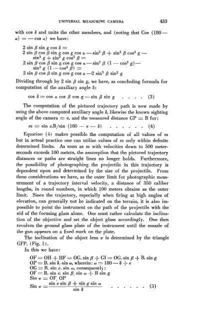
UNIVERSAL MEASURING CAMERA 433<br />
with cas 8 and unite the other members, and (noting that Cas (180a)<br />
= -cos a) we have:<br />
2 sin {3 sin g cas 8=<br />
2 sin {3 cas {3 sin g cas g cas a - sin 2 {3 + sin 2 {3 cos 2 g -<br />
sin 2 g + sin 2 g cos 2 {3=<br />
2 sin {3 cos {3 sin g cas g cas a-sin 2 {3 (1- cos 2 g)sin:!g<br />
(1- cos 2 (3) =<br />
2 sin {3 cos {3 sin g cos g cas a -2 sin 2 {3 sin 2 g<br />
Dividing through by 2 sin f3 sin g, we have, as concluding formula for<br />
computation of the auxiliary angle 8:<br />
cos 8= cos a COS {3 cos g - sin {3 sin g (3)<br />
The computation of the pictured trajectory path is now made by<br />
using the above computed auxiliary angle 8, likewise the known sighting<br />
angle of the camera = e, and the measured distance GP = B for:<br />
m = sin e.Bjsin (180 - e - 8) (4)<br />
Equation (4,) makes possible the computation of all values of m<br />
but in actual practice one can utilize values of m only within definite<br />
determined limits. As soon as m with velocities down to 500 meterseconds<br />
exceeds 100 meters, the assumption that the pictured trajectory<br />
distances or paths are straight lines no longer holds. Furthermore,<br />
the possibility of photographing the projectile in this trajectory is<br />
dependent upon and determined by the size of the projectile. From<br />
these considerations we have, as the outer limit for photographic mtlasurement<br />
of a trajectory interval velocity, a distance of 350 caliber<br />
lengths, in round numbers, in which 100 meters obtains as the outer<br />
limit. Since the trajectory, especially when firing at high angles of<br />
elevation, can generally not be indicated on the terrain, it is also impossible<br />
to point the instrument on the path of the projectile with the<br />
aid of the focusing glass alone. One must rather calculate the inclination<br />
of the objective and set the object glass accordingly. One then<br />
revolves the ground glass plate of the instr!1ment until the muzzle of<br />
the gun appears on a fixed mark on the plate.<br />
The inclination of the object lens r. is determined by the triangle<br />
GFP. (Fig. 1.1.<br />
In this we haw:<br />
OF = OH + HF = OG.sin {3 + GI = OG. sin {3 + B. sin g<br />
OP = B. sin ()! sin (r), wherein: (r) =<br />
180- 8+ e<br />
OG= B. sin ~,sin "', consequently:<br />
OF = B. sin e. sin {3, sin (r) + B sin g<br />
Sin r.= OF .OP<br />
Sin r. = sin je sin {3 ~ s~ng sin (r) (5)<br />
sm ()


