Pseudo-Noise (PN) Ranging Systems - CCSDS
Pseudo-Noise (PN) Ranging Systems - CCSDS
Pseudo-Noise (PN) Ranging Systems - CCSDS

Create successful ePaper yourself
Turn your PDF publications into a flip-book with our unique Google optimized e-Paper software.
<strong>CCSDS</strong> INFORMATIONAL REPORT CONCERNING PSEUDO-NOISE RANGING SYSTEMS<br />
2 <strong>PN</strong> REGENERATIVE RANGING SYSTEMS<br />
2.1 FUNDAMENTALS OF <strong>PN</strong> RANGING SCHEMES<br />
A ranging-sequence system is a system in which a periodic binary (±1) ranging sequence<br />
modulates an uplink carrier 2 to produce a signal that is transmitted from an Earth station to a<br />
transponder in the spacecraft whose range from the Earth station is to be measured. This<br />
modulated uplink carrier is received and processed by the spacecraft transponder, either in a<br />
simple turnaround (non-regenerative) manner or by detection and regeneration to remove<br />
uplink noise, and then retransmitted to the Earth station where the round-trip delay between<br />
the transmitted and received signals is measured. Regenerative ranging provides such a<br />
substantial power advantage over non-regenerative ranging, up to 30 dB in proposed systems<br />
that it can be expected to be the baseline in most of future deep space missions. The term<br />
‘<strong>Pseudo</strong>-<strong>Noise</strong> (<strong>PN</strong>) ranging’ refers in a strict sense to the use of a ranging-sequence system<br />
in which the ranging sequence is a logical combination of the so-called range clock-sequence<br />
and several <strong>Pseudo</strong>-<strong>Noise</strong> (<strong>PN</strong>) sequences. The range clock sequence is the alternating +1<br />
and –1 sequence of period 2. A <strong>Pseudo</strong>-<strong>Noise</strong> (<strong>PN</strong>) sequence is a binary ±1 sequence of<br />
period L whose periodic autocorrelation function has peak value +L and all (L–1) off-peak<br />
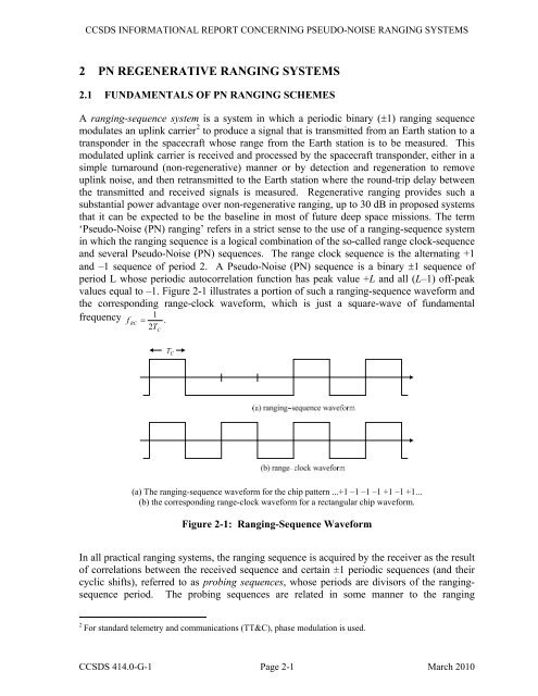
values equal to –1. Figure 2-1 illustrates a portion of such a ranging-sequence waveform and<br />
the corresponding range-clock waveform, which is just a square-wave of fundamental<br />
frequency 1<br />
f RC = .<br />
2T<br />
C<br />
(a) The ranging-sequence waveform for the chip pattern ...+1 –1 –1 –1 +1 –1 +1...<br />
(b) the corresponding range-clock waveform for a rectangular chip waveform.<br />
Figure 2-1: <strong>Ranging</strong>-Sequence Waveform<br />
In all practical ranging systems, the ranging sequence is acquired by the receiver as the result<br />
of correlations between the received sequence and certain ±1 periodic sequences (and their<br />
cyclic shifts), referred to as probing sequences, whose periods are divisors of the rangingsequence<br />
period. The probing sequences are related in some manner to the ranging<br />
2 For standard telemetry and communications (TT&C), phase modulation is used.<br />
<strong>CCSDS</strong> 414.0-G-1 Page 2-1 March 2010