Pseudo-Noise (PN) Ranging Systems - CCSDS
Pseudo-Noise (PN) Ranging Systems - CCSDS
Pseudo-Noise (PN) Ranging Systems - CCSDS

You also want an ePaper? Increase the reach of your titles
YUMPU automatically turns print PDFs into web optimized ePapers that Google loves.
<strong>CCSDS</strong> INFORMATIONAL REPORT CONCERNING PSEUDO-NOISE RANGING SYSTEMS<br />
2.8.3.4 TM BER<br />
In the absence of ranging, the telemetry symbol error probability is<br />
P<br />
id , TM<br />
( e)<br />
1<br />
=<br />
2<br />
erfc<br />
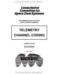
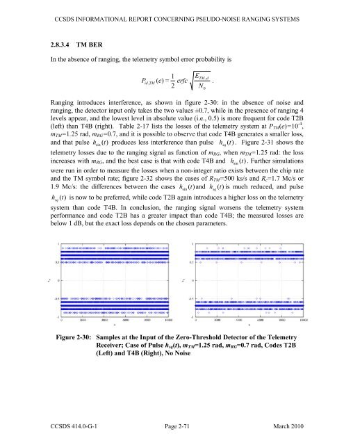
<strong>Ranging</strong> introduces interference, as shown in figure 2-30: in the absence of noise and<br />
ranging, the detector input only takes the two values ±0.7, while in the presence of ranging 4<br />
levels appear, and the lowest level in absolute value (i.e., 0.5) is more frequent for code T2B<br />
(left) than T4B (right). Table 2-17 lists the losses of the telemetry system at PTM(e)=10 -4 ,<br />
mTM=1.25 rad, mRG=0.7, and it is possible to observe that code T4B generates a smaller loss,<br />
and that pulse h ( ) produces less interference than pulse (t)<br />
. Figure 2-31 shows the<br />
sin t<br />
telemetry losses due to the ranging signal as function of mRG, when mTM=1.25 rad: the loss<br />
increases with mRG, and the best case is that with code T4B and h sin ( t)<br />
. Further simulations<br />
were run in order to measure the losses when a non-integer ratio exists between the chip rate<br />
and the TM symbol rate; figure 2-32 shows the cases of RTM=500 ks/s and Rc=1.7 Mc/s or<br />
1.9 Mc/s: the differences between the cases h ( ) and (t)<br />
is much reduced, and pulse<br />
hsq (t)<br />
is now to be preferred, while code T2B again introduces a higher loss on the telemetry<br />
system than code T4B. In conclusion, the ranging signal worsens the telemetry system<br />
performance and code T2B has a greater impact than code T4B; the measured losses are<br />
below 1 dB, but the exact loss depends on the chosen parameters.<br />
Figure 2-30: Samples at the Input of the Zero-Threshold Detector of the Telemetry<br />
Receiver; Case of Pulse hsq(t), mTM=1.25 rad, mRG=0.7 rad, Codes T2B<br />
(Left) and T4B (Right), No <strong>Noise</strong><br />
<strong>CCSDS</strong> 414.0-G-1 Page 2-71 March 2010<br />
sin t<br />
E<br />
TM , d<br />
N<br />
0<br />
.<br />
h sq<br />
h sq