Pseudo-Noise (PN) Ranging Systems - CCSDS
Pseudo-Noise (PN) Ranging Systems - CCSDS
Pseudo-Noise (PN) Ranging Systems - CCSDS

You also want an ePaper? Increase the reach of your titles
YUMPU automatically turns print PDFs into web optimized ePapers that Google loves.
<strong>CCSDS</strong> INFORMATIONAL REPORT CONCERNING PSEUDO-NOISE RANGING SYSTEMS<br />
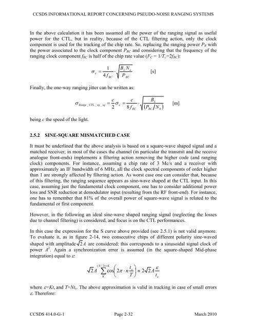
In the above calculation it has been assumed all the power of the ranging signal as useful<br />
power for the CTL, but in reality, because of the CTL filtering action, only the clock<br />
component is used for the tracking of the chip rate. So, replacing the ranging power PR with<br />
the power associated to the clock component PRC and considering that the frequency of the<br />
ranging clock component fRC is half of the chip rate value (FC = 1/Tc=2fRC):<br />
1<br />
=<br />
4<br />
⋅<br />
B<br />
L o<br />
σ ε<br />
[s]<br />
f RC P RC<br />
Finally, the one-way ranging jitter can be written as:<br />
being c the speed of the light.<br />
<strong>CCSDS</strong> 414.0-G-1 Page 2-32 March 2010<br />
N<br />
c c BL<br />
σ Range _ CTL _ sq _ sq = σ ε = ⋅<br />
[m]<br />
2 8 f N<br />
2.5.2 SINE-SQUARE MISMATCHED CASE<br />
RC<br />
( P )<br />
It must be underlined that the above analysis is based on a square-wave shaped signal and a<br />
matched receiver; in most of the cases the channel (in particular the transmit and the receive<br />
analogue front-ends) implements a filtering action removing the higher code (and ranging<br />
clock) components. For instance, assuming a chip rate of 3 Mc/s and a receiver with<br />
approximately an IF bandwidth of 6 MHz, all the clock spectral components of order higher<br />
than 1 are strongly affected by filtering action. As worst case one can consider that, because<br />
of this filtering, the ranging sequence appears as sine-wave shaped at the CTL input. In this<br />
case, assuming just the fundamental clock component, one has to consider additional power<br />
loss and SNR reduction at demodulator input (resulting from the RF front-end). For instance,<br />
one has to remember that 81% of the overall power of square-wave signal is related to the<br />
fundamental or first component.<br />
However, in the following an ideal sine-wave shaped ranging signal (neglecting the losses<br />
due to channel filtering) is considered, and focus is on the CTL performances.<br />
In this case the expression for the S curve above provided (see 2.5.1) is not valid anymore.<br />
To evaluate it, as in figure 2-14, two consecutive chips of different polarity sine-waved<br />
shaped with amplitude 2 A are considered: this corresponds to a sinusoidal signal clock of<br />
power A 2 . Again a synchronization error is assumed (in the square-shaped Mid-phase<br />
integration) equal to ε:<br />
2A<br />
( N / 2)<br />
K<br />
∑<br />
K<br />
+<br />
⎛<br />
cos⎜2<br />
⎝<br />
t ⎞<br />
⎟<br />
T ⎠<br />
RC<br />
s π ⋅ n ≈ 2 2<br />
where ε=Kts and T=Nts. The above approximation is valid in tracking in case of small errors<br />
ε. Therefore:<br />
t<br />
A<br />
ε<br />
s<br />
0