MA JOR 2 NCH - Euroconfort
MA JOR 2 NCH - Euroconfort
MA JOR 2 NCH - Euroconfort

You also want an ePaper? Increase the reach of your titles
YUMPU automatically turns print PDFs into web optimized ePapers that Google loves.
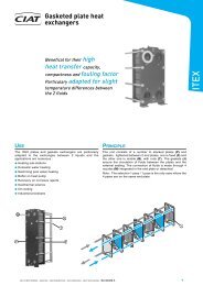
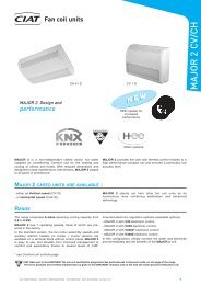
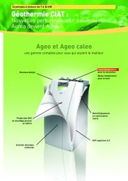
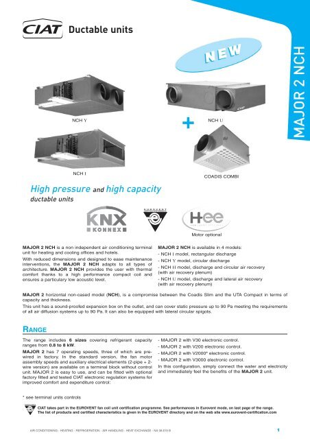
Ductable units<br />
<strong>MA</strong><strong>JOR</strong> 2 <strong>NCH</strong> is a non independent air conditioning terminal<br />
unit for heating and cooling offices and hotels.<br />
With reduced dimensions and designed to ease maintenance<br />
interventions, the <strong>MA</strong><strong>JOR</strong> 2 <strong>NCH</strong> adapts to all types of<br />
architecture. <strong>MA</strong><strong>JOR</strong> 2 <strong>NCH</strong> provides the user with thermal<br />
comfort thanks to a high performance compact coil and<br />
ensures a particulary low acoustic level.<br />
* see terminal units controls<br />
AIR CONDITIONING - HEATING - REFRIGERATION - AIR HANDLING - HEAT EXCHANGE - NA 08.619 B<br />
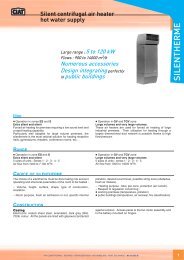
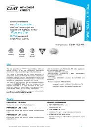
<strong>MA</strong><strong>JOR</strong> 2 <strong>NCH</strong> is available in 4 models:<br />
- <strong>NCH</strong> I model, rectangular discharge<br />
- <strong>NCH</strong> Y model, circular discharge<br />
- <strong>NCH</strong> H model, discharge and circular air recovery<br />
(with air recovery plenum)<br />
- <strong>NCH</strong> U model, discharge and lateral air recovery<br />
(with air recovery plenum)<br />
<strong>MA</strong><strong>JOR</strong> 2 horizontal non-cased model (<strong>NCH</strong>), is a compromise between the Coadis Slim and the UTA Compact in terms of<br />
capacity and thickness.<br />
This unit has a sound-proofed expansion box on the outlet, and can cover static pressure up to 90 Pa meeting the requirements<br />
of all air diffusion systems up to 90 Pa. It can also be equipped with lateral circular spigots.<br />
RANGE<br />
<strong>NCH</strong> Y<br />
<strong>NCH</strong> I<br />
High pressure and high capacity<br />
ductable units<br />
The range includes 6 sizes covering refrigerant capacity<br />
ranges from 0.8 to 8 kW.<br />
<strong>MA</strong><strong>JOR</strong> 2 has 7 operating speeds, three of which are prewired<br />
in factory. In the standard version, the fan motor<br />
assembly speeds and auxiliary electrical elements (2-pipe + 2wire<br />
version) are available on a terminal block without control<br />
unit. <strong>MA</strong><strong>JOR</strong> 2 is easy to use, and can be fitted with optional<br />
factory fitted and tested CIAT electronic regulation systems for<br />
improved comfort and expenditure control:<br />
+ <strong>NCH</strong><br />
U<br />
COADIS COMBI<br />
Motor optional<br />
- <strong>MA</strong><strong>JOR</strong> 2 with V30 electronic control.<br />
- <strong>MA</strong><strong>JOR</strong> 2 with V200 electronic control.<br />
- <strong>MA</strong><strong>JOR</strong> 2 with V2000 ® electronic control.<br />
- <strong>MA</strong><strong>JOR</strong> 2 with V3000 electronic control.<br />
In this configuration, simply connect the water and electricity<br />
and immediately feel the benefits of the <strong>MA</strong><strong>JOR</strong> 2 unit.<br />
CIAT takes part in the EUROVENT fan coil unit certification programme. See performances in Eurovent mode, on last page of the range.<br />
The list of products and certified characteristics is given in the EUROVENT directory and on the web site www.eurovent-certification.com<br />
1<br />
<strong>MA</strong><strong>JOR</strong> 2 <strong>NCH</strong>
2<br />
Ductable units<br />
TECHNICAL DESCRIPTION<br />
Casing<br />
Galvanized sheet metal<br />
Insulation in melamine resin, open cells flexible foam, with<br />
aluminium film, M1, 10 mm thick.<br />
Pre-cut hole for treated fresh air inlet.<br />
Sound-proofed expansion box integrated in the unit<br />
Bottom inspection panels for access and dismantling of the<br />
unit’s main components.<br />
Y Mode: one or more ∅ 200 mm circular spigots in autoextinguishable<br />
polymer material.<br />
I Model: rectangular sleeve discharge.<br />
Upper panel with fixation oblong holes.<br />
Water coil (2 or 4-pipe system)<br />
New concept of high performance compact coil, with new<br />
geometry fins.<br />
Galvanized sheet metal.<br />
Copper tubes, continuous fins in aluminium<br />
Hydraulic connectors of coils piping with 40 mm<br />
between axis.<br />
Connections on the left or right sides of the unit, when facing<br />
the discharge.<br />
Air vents and drains integrated in the piping.<br />
Nominal pressure: 16 bar (at 20°C).<br />
Test pressure 24 Bar.<br />
Max water temperature: 110 °C (PN 10).<br />
Electrical battery (2-pipe system +<br />
electric)<br />
230/1/50 monotubes electrical elements inserted in the<br />
aluminium block.<br />
2 capillary type temperature limiters, manual and automatic<br />
reset, inserted in the aluminium block<br />
Condensates recovery drain pan<br />
Polymer material drain pan<br />
Without water retention, condensates drain at the same level<br />
CONTROL DEVICES<br />
Range of wall-mounted electromechanical thermostats<br />
V30 and V200 electronic range.<br />
ACCESSORIES<br />
Extra diam. 200mm discharge sleeve (<strong>NCH</strong> Y).<br />
Intake sleeve for connection to a rectangular duct.<br />
Recovery plenum with diam. 200 mm intake inlet(s) for ducting<br />
(H application).<br />
Diam. 100 mm smooth sleeve for treated fresh air inlet.<br />
OPTION (CONSULT US)<br />
- Additional spigots (<strong>NCH</strong> Y).<br />
- Other spigot diameters (<strong>NCH</strong> Y).<br />
- 60 Hz operation (230V).<br />
- High Energy Efficiency (HEE) motor.<br />
<strong>MA</strong><strong>JOR</strong> 2 <strong>NCH</strong><br />
as the drain pan bottom, inclined.<br />
Drain connectors manually reversible towards the front<br />
or the rear.<br />
4 drainage diameters: 15, 16, 22 or 28 mm in standard.<br />
Fan motor assembly<br />
■ Motor<br />
7 speeds, 3 are pre-wired in factory (possibility of modifying<br />
this wiring on site).<br />
Enclosed type, tropicalised, with protected shaft and<br />
ball-bearings.<br />
Permanent capacitor.<br />
Automatic thermal protector with standard thermal cut-out<br />
on the coil.<br />
Resilient mounts.<br />
Electrical supply 230/1/50.<br />
Reduced electrical consumption.<br />
■ Fan(s)<br />
Galvanized sheet metal casing.<br />
Dynamically-balanced dual-inlet impeller(s) with forwardcurved<br />
blades. V0 fire rating.<br />
Air filter<br />
Positioned on the fan coil intake.<br />
Flexible filtering media in polyester fibers, cleanable.<br />
Efficiency Class EN 779: G3.<br />
Fire resistance: M1.<br />
Electrical box<br />
Enclosed box on the hydraulic connections side (<strong>NCH</strong>).<br />
Electrical connection terminal box on DIN railing as per EN<br />
50022- 7.5 mm depth.<br />
Cables stops for customer's connection.<br />
Note: Refer to installation brochures for futher information.<br />
V2000 ® and V3000 communicating electronic range<br />
LON control, consult us.<br />
Diam. 100 mm smooth sleeve with self-adjustable module for<br />
treated fresh air inlet.<br />
Resilient mounts for fixations.<br />
Condensates draining pump.<br />
AIR CONDITIONING - HEATING - REFRIGERATION - AIR HANDLING - HEAT EXCHANGE - NA 08.619 B
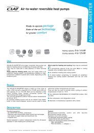
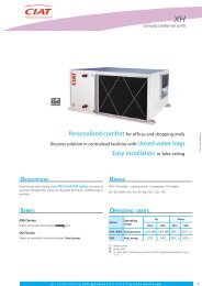
Ductable units<br />
DIMENSIONS OF <strong>NCH</strong> MODEL (RECTANGULAR DISCHARGE)<br />
Between axis = AG<br />
Hydraulic connections<br />
<strong>MA</strong><strong>JOR</strong> 2<br />
<strong>NCH</strong> model I<br />
Air filter<br />
disassembled<br />
from rear<br />
Electrical<br />
connection box<br />
Condensates<br />
recovery pan<br />
Removable panels for<br />
access from below to fan motor<br />
unit and coil<br />
Between axis=725<br />
Pre-stamped hole for fresh<br />
air (accessory module)<br />
Double sleeve A-B<br />
A cold water coil B hot water coil<br />
( 2-pipe system) (4-pipe system)<br />
Oblong slots<br />
12,7 x 25<br />
AE AF AG AH AI<br />
426 N 765 505 535 400 400 26<br />
428 N 965 705 735 600 600 30<br />
430 N 1165 905 935 800 800 40<br />
432 N 1365 1105 1135 1000 1000 46<br />
434 / 435 N 1565 1305 1335 1200 1200 54<br />
AIR CONDITIONING - HEATING - REFRIGERATION - AIR HANDLING - HEAT EXCHANGE - NA 08.619 B<br />
Sleeve OD 150 x AI<br />
Corresponds to<br />
the reservation<br />
dimensions in the wall<br />
150 x AH<br />
Sound-proof expansion box<br />
(ready to be placed against a wall<br />
with foam seal accessory for fitting<br />
under a structural beam)<br />
NOTE: for satisfactory operation a distance of > 250 mm<br />
at the unit intake must be respected<br />
Double deflection rectangular<br />
discharge grille, 426 N, 428 N<br />
and 430 N<br />
(others sizes, consult us)<br />
DETAIL A<br />
Mass<br />
kg<br />
Reversible<br />
connectors<br />
Condensate drain<br />
Ø15-16-22 and 28 mm<br />
Condensate drain<br />
Dimensional<br />
drawing<br />
7065443<br />
3<br />
<strong>MA</strong><strong>JOR</strong> 2 <strong>NCH</strong>
4<br />
Ductable units<br />
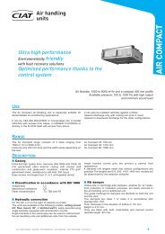
DIMENSIONS OF <strong>NCH</strong> MODEL (CIRCULAR DISCHARGE)<br />
Between axis = AK<br />
Hydraulic connections<br />
<strong>MA</strong><strong>JOR</strong> 2<br />
<strong>NCH</strong> model Y<br />
Air filter<br />
disassembled<br />
from rear<br />
Electrical<br />
connection box<br />
Condensates<br />
recovery pan<br />
Removable panels for<br />
access from below to fan<br />
motor unit and coil<br />
Between axis = 725<br />
Pre-stamped hole for conditioned fresh<br />
air (accessory module)<br />
Double sleeve A-B<br />
A cold water coil B hot water coil<br />
( 2-pipe system) (4-pipe system)<br />
2-pre-stamped<br />
holes, Ø 200 mm<br />
Oblong slots<br />
12.7 x 25<br />
Sound-proof<br />
expansion box<br />
AI AJ AK<br />
426 N 765 505 535 26<br />
428 N 965 705 735 30<br />
430 N 1165 905 935 40<br />
432 N 1365 1105 1135 46<br />
434 / 435 N 1565 1305 1335 54<br />
<strong>MA</strong><strong>JOR</strong> 2 <strong>NCH</strong><br />
NOTE: for satisfactory operation a distance of<br />
> 250 mm at the unit intake must be respected<br />
<strong>NCH</strong> 426 N<br />
<strong>NCH</strong> 428 N<br />
<strong>NCH</strong> 430 N<br />
<strong>NCH</strong> 432 N<br />
<strong>NCH</strong> 434 / 435 N<br />
PLENUM TYPES<br />
Ø 200 mm spigot(s)<br />
X = number of spigots<br />
Mass<br />
kg<br />
Max air flow rate advised per<br />
Ø200 outlet: 400 m 3/h<br />
* See user's brochure for<br />
aeraulic balance<br />
DETAIL A<br />
Reversible<br />
connectors<br />
Condensate drain<br />
Ø15-16-22 and 28 mm<br />
Dimensional<br />
drawing<br />
5976176<br />
AIR CONDITIONING - HEATING - REFRIGERATION - AIR HANDLING - HEAT EXCHANGE - NA 08.619 B<br />
Condensates drain
Ductable units<br />
DIMENSIONS OF <strong>NCH</strong> ACCESSORIES FOR I AND Y MODELS<br />
Recovery sleeve, smooth sheet<br />
metal, rectangular, without insulation<br />
Air intake section 200 x AF<br />
Max. air flow rate recommended per Ø 200 outlet: 500 m 3/h<br />
<strong>MA</strong><strong>JOR</strong> 2<br />
<strong>NCH</strong><br />
Air filter lodging<br />
to be dismantled<br />
underneath the unit<br />
AF<br />
X<br />
(Number of spigots)<br />
426 N 450 1<br />
428 N 650 2<br />
430 N 850 2<br />
432 N 1050 3<br />
434 / 435 N 1250 4<br />
Note: In the case of a plenum without filter, the installer should<br />
allow for his own filter on the recovery grille.<br />
AIR CONDITIONING - HEATING - REFRIGERATION - AIR HANDLING - HEAT EXCHANGE - NA 08.619 B<br />
Recovery plenum, smooth sheet metal,<br />
∅ 200 mm for H application, with filter<br />
Conditioned fresh air knockout<br />
Air filter lodging<br />
to be dismantled<br />
underneath the unit<br />
Conditioned<br />
fresh air<br />
knockout<br />
Ø 200 x X<br />
Ø 200 spigot same<br />
number as air outlets<br />
(1 to 4)<br />
Recovery plenum, smooth sheet<br />
metal ∅ 200 for H application, without<br />
filter<br />
Ø 200 spigot same<br />
number as air outlets (1 to 4)<br />
5<br />
<strong>MA</strong><strong>JOR</strong> 2 <strong>NCH</strong>
6<br />
Ductable units<br />
DIMENSIONS OF <strong>NCH</strong> U MODEL<br />
Pre-stamped hole<br />
for conditioned<br />
fresh air<br />
(accessory module)<br />
Between axis = AN<br />
241<br />
Hydraulic connections<br />
<strong>MA</strong><strong>JOR</strong> 2<br />
<strong>NCH</strong> U model<br />
Air filter<br />
disassembled<br />
from rear<br />
Spigots Ø 200<br />
Pre-stamped hole<br />
for conditioned fresh air<br />
Ø 100 or 125 mm<br />
Electrical<br />
connection box<br />
Condensates<br />
recovery pan<br />
1012<br />
Removable panels for<br />
access from below to fan<br />
motor unit and coil<br />
Between axis = 725<br />
Pre-stamped hole<br />
for fresh air<br />
(accessory module)<br />
AL AM AN<br />
426 N* 780 505 535 28<br />
428 N* 980 705 735 33<br />
* Both sizes are available with an HEE motor<br />
Spigots Ø 200<br />
Double sleeve A-B<br />
A cold water coil B hot water coil<br />
( 2 pipe system) (4 pipe system)<br />
Oblong slots<br />
12.7 x 25<br />
<strong>MA</strong><strong>JOR</strong> 2 <strong>NCH</strong><br />
Mass<br />
kg<br />
DETAIL A<br />
Reversible<br />
connectors<br />
Condensate drain<br />
Ø15-16-22 and 28 mm<br />
Dimensional<br />
drawing<br />
7106685<br />
AIR CONDITIONING - HEATING - REFRIGERATION - AIR HANDLING - HEAT EXCHANGE - NA 08.619 B<br />
Condensates drain
Ductable units<br />
TECHNICAL CHARACTERISTICS<br />
Piping diameter at fan coil outlets (tapped connectors)<br />
The diameters of the female tapped fittings on coil connection pipes are standardised (see above drawing dimension T)<br />
2- pipe sytem<br />
4- pipe sytem<br />
Standard unit<br />
<strong>MA</strong><strong>JOR</strong> 2 426 N 428 N 430 N 432 N 434 N 435 N<br />
Heating or cooling<br />
coil<br />
3/8 " 3/8 " 3/8 " 3/8 " 1/2" 1/2 "<br />
Cooling coil 3/8 " 3/8 " 3/8 " 3/8 " 1/2 " 1/2 "<br />
Heating coil 3/8 " 3/8 " 3/8 " 3/8 " 3/8 " 3/8 "<br />
Diameters of valve outlets (threaded connectors)<br />
The diameters of the valves’ male threaded connections are standardised (see above drawing dimension T2)<br />
<strong>MA</strong><strong>JOR</strong> 2 426 N 428 N 430 N 432 N 434 N 435 N<br />
2- pipe sytem<br />
Heating or cooling<br />
coil<br />
1/2 " 1/2 " 1/2 " 1/2 " 3/4" 3/4"<br />
4- pipe sytem<br />
Cooling coil<br />
Heating coil<br />
1/2 "<br />
1/2 "<br />
1/2 "<br />
1/2 "<br />
1/2 "<br />
1/2 "<br />
1/2 "<br />
1/2 "<br />
3/4"<br />
1/2 "<br />
3/4"<br />
1/2 "<br />
For units fitted with customer’s control valves, an intermediate two-part male/female connector is needed between the coil<br />
connector and the valve(s). This connector is available as an accessory (1, 2 or 4 connectors are required depending on the<br />
configuration (2 or 4-pipe) and the valve type (2-way or 4-way) - consult us).<br />
When a CIAT valve-based control system is used, the two-part connector is integrated in the control loop.<br />
Coils content (in litres)<br />
<strong>MA</strong><strong>JOR</strong> 2 426 N 428 N 430 N 432 N 434 N 435 N<br />
2- pipe sytem<br />
Heating or cooling<br />
coil<br />
0,53 0,76 0,99 1,32 1,58 1,58<br />
4- pipe sytem<br />
Cooling coil<br />
Heating coil<br />
0,53<br />
0,13<br />
0,76<br />
0,13<br />
0,99<br />
0,25<br />
1,32<br />
0,20<br />
1,58<br />
0,24<br />
1,58<br />
0,24<br />
Motor electrical characteristics (230/1/50)<br />
* Sizes 426 SP N, 428 SP N, 432 SP N characteristics are identical to those of size 434 N<br />
AIR CONDITIONING - HEATING - REFRIGERATION - AIR HANDLING - HEAT EXCHANGE - NA 08.619 B<br />
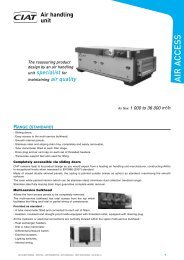
Unit with<br />
valve (optional)<br />
Note: images of the valve motors are for information only and are not contractually binding.<br />
<strong>MA</strong><strong>JOR</strong> 2<br />
Absorbed power<br />
(W)<br />
Absorbed Current<br />
(A)<br />
Motor<br />
ref.<br />
426 N 428 N 430 N 432 N 434 N 435 N<br />
R1 63 101 116 115 149 163<br />
R2 55 88 95 94 132 142<br />
R3 47 73 78 78 117 124<br />
R4 40 63 66 64 103 106<br />
R5 36 58 58 57 94 97<br />
R6 32 52 52 51 86 86<br />
R7 28 47 47 45 77 76<br />
R1 0,27 0,44 0,50 0,50 0,65 0,71<br />
R2 0,24 0,38 0,41 0,41 0,57 0,62<br />
R3 0,20 0,32 0,34 0,34 0,51 0,54<br />
R4 0,17 0,27 0,29 0,28 0,45 0,46<br />
R5 0,16 0,25 0,25 0,25 0,41 0,42<br />
R6 0,14 0,23 0,23 0,22 0,37 0,37<br />
R7 0,12 0,20 0,20 0,20 0,33 0,33<br />
DN10<br />
7<br />
<strong>MA</strong><strong>JOR</strong> 2 <strong>NCH</strong>
8<br />
Ductable units<br />
THER<strong>MA</strong>L PERFOR<strong>MA</strong>NCES FOR NON-CASED MODELS<br />
<strong>MA</strong><strong>JOR</strong> 2 <strong>NCH</strong><br />
Cold water temperature: 7 / 12°C, summer air temp.: 27°C 50 % RH - Hot water temperature: 90 / 70°C, winter air temp: 19°C.<br />
Major 2<br />
<strong>NCH</strong><br />
426 N<br />
428 N<br />
430 N<br />
432 N<br />
434 N<br />
435 N<br />
Motor<br />
ref.<br />
Air flow<br />
m 3/h<br />
Available<br />
static<br />
pressure<br />
Pa (1)<br />
Heating<br />
capacity<br />
2-pipe<br />
system<br />
W<br />
Cooling capacity<br />
W<br />
Heating<br />
capacity<br />
4-pipe<br />
system<br />
W coil<br />
ISO or NR<br />
comfort<br />
level<br />
Mean air<br />
temperature rise in K (2)<br />
Auxiliary electric battery<br />
230 / 1 / 50<br />
Totale Sensible 1 R 2R<br />
R1 470 40 7 030 2 890 2 160 4 030 33<br />
3,8<br />
7,6<br />
R2 425 6 460 2 680 1 990 3 810 31 4,2 8,4<br />
R3 375 5 810 2 430 1 780 3 550 28 4,8 9,5<br />
R4 325 5 100 2 150 1 570 3 250 24 600 5,5 1 200 11,0<br />
R5 265 4 300 1 840 1 330 2 880 20 6,7 13,4<br />
R6 210 3 480 1 510 1 080 2 470
TARIF HT<br />
<strong>NCH</strong><br />
I Model<br />
with<br />
rectangular<br />
discharge<br />
<strong>NCH</strong><br />
Y Model (1)<br />
with<br />
circular<br />
discharge<br />
<strong>MA</strong><strong>JOR</strong> 2<br />
HORIZONTAL<br />
WITHOUT CASING<br />
426 N<br />
428 N*<br />
430 N<br />
432 N*<br />
434 N<br />
435 N<br />
426 N*<br />
428 N*<br />
430 N<br />
432 N*<br />
434 N<br />
435 N<br />
* Extra price for <strong>NCH</strong> model<br />
size 426 SP N, 428 SP N<br />
or 432 SP N<br />
(consult us for characteristics)<br />
(1) Price for U model, consult us.<br />
Ductable units<br />
Water coil only<br />
Connections on the left Connections on the right<br />
2- pipe<br />
system<br />
4- pipe<br />
system<br />
2- pipe<br />
system<br />
AIR CONDITIONING - HEATING - REFRIGERATION - AIR HANDLING - HEAT EXCHANGE - NA 08.619 B<br />
STANDARD UNIT<br />
4- pipe<br />
system<br />
Code 5877000 5877024 5877006 5877030<br />
Connections on the left<br />
2- pipe + 2 wire system<br />
Water coil + electric battery<br />
Connections on the right<br />
2- pipe + 2 wire system<br />
1 element 2 elements 1 element 2 elements<br />
600 W<br />
5877048<br />
+ 1200 W<br />
5877072<br />
+ 600 W<br />
5877054<br />
● ● ● ● ● ● ● ● ●<br />
Code 5877001 5877025 5877007 5877031<br />
+ 800 W<br />
5877049<br />
+ 1600 W<br />
5877073<br />
+ 800 W<br />
5877055<br />
● ● ● ● ● ● ● ● ●<br />
Code 5877002 5877026 5877008 5877032<br />
+ 1200 W<br />
5877050<br />
+ 2400 W<br />
5877074<br />
+ 1200 W<br />
5877056<br />
● ● ● ● ● ● ● ● ●<br />
Code 5877003 5877027 5877009 5877033<br />
+ 1400 W<br />
5877051<br />
+ 2800 W<br />
5877075<br />
+ 1400 W<br />
5877057<br />
● ● ● ● ● ● ● ● ●<br />
Code 5877004 5877028 5877010 5877034<br />
+ 2000 W<br />
5877052<br />
+ 4000 W<br />
5877076<br />
+ 2000 W<br />
5877058<br />
● ● ● ● ● ● ● ● ●<br />
Code 5877005 5877029 5877011 5877035<br />
+ 2000 W<br />
5877053<br />
+ 4000 W<br />
5877077<br />
+ 2000 W<br />
5877059<br />
● ● ● ● ● ● ● ● ●<br />
Code 5877012 5877036 5877018 5877042<br />
+ 600 W<br />
5877060<br />
+ 1200 W<br />
5877084<br />
+ 600 W<br />
5877066<br />
● ● ● ● ● ● ● ● ●<br />
Code 5877013 5877037 5877019 5877043<br />
+ 800 W<br />
5877061<br />
+ 1600 W<br />
5877085<br />
+ 800 W<br />
5877067<br />
● ● ● ● ● ● ● ● ●<br />
Code 5877014 5877038 5877020 5877044<br />
+ 1200 W<br />
5877062<br />
+ 2400 W<br />
5877086<br />
+ 1200 W<br />
5877068<br />
● ● ● ● ● ● ● ● ●<br />
Code 5877015 5877039 5877021 5877045<br />
+ 1400 W<br />
5877063<br />
+ 2800 W<br />
5877087<br />
+ 1400 W<br />
5877069<br />
● ● ● ● ● ● ● ● ●<br />
Code 5877016 5877040 5877022 5877046<br />
+ 2000 W<br />
5877064<br />
+ 4000 W<br />
5877088<br />
+ 2000 W<br />
5877070<br />
● ● ● ● ● ● ● ● ●<br />
Code 5877017 5877041 5877023 5877047<br />
+ 2000 W<br />
5877065<br />
+ 4000 W<br />
5877089<br />
+ 2000 W<br />
5877071<br />
● ● ● ● ● ● ● ● ●<br />
Code E040290<br />
● ●<br />
See page on control devices for a complete offer : terminal unit + control<br />
+ 1200 W<br />
5877078<br />
+ 1600 W<br />
5877079<br />
+ 2400 W<br />
5877080<br />
+ 2800 W<br />
5877081<br />
+ 4000 W<br />
5877082<br />
+ 4000 W<br />
5877083<br />
+ 1200 W<br />
5877090<br />
+ 1600 W<br />
5877091<br />
+ 2400 W<br />
5877092<br />
+ 2800 W<br />
5877093<br />
+ 4000 W<br />
5877094<br />
+ 4000 W<br />
5877095<br />
9<br />
<strong>MA</strong><strong>JOR</strong> 2 <strong>NCH</strong>
10<br />
Ductable units<br />
ACCESSORIES FOR NON-CASED <strong>MA</strong><strong>JOR</strong> 2 (SUPPLIED SEPARATELY)<br />
<strong>MA</strong><strong>JOR</strong> 2 <strong>NCH</strong><br />
Model Description 426 N 428 N 430 N 432 N 434 N 435 N<br />
<strong>NCH</strong> SU1<br />
<strong>NCH</strong> MO1<br />
<strong>NCH</strong><br />
Model Description 426 N 428 N 430 N 432N 434 N 435 N<br />
<strong>NCH</strong> PR1<br />
<strong>NCH</strong> M18<br />
<strong>NCH</strong> PL5<br />
<strong>NCH</strong> PL50<br />
<strong>NCH</strong><br />
MO7<br />
MO4<br />
Condensate drain pump mounted on the unit with overflow safety device.<br />
� 7l/h maximum flow for 1m draining height and 5m maximal length of piping.<br />
� 6l/h maximum flow for 1m draining height and 10m maximal length of piping.<br />
Draining: 8mm internal diameter flexible tube, 8mm diameter nozzle.<br />
For higher drain heights, consult us.<br />
One regulation for each valve must be added to allow slaving the overflow<br />
safety device to the valve closing (condensates stopped).<br />
Approximate calculation of the condensed water flow:<br />
Qv (l/h) =<br />
Resilient mounts supplied separately<br />
(4 per unit necessary)<br />
Rectangular smooth sheet metal recovery sleeve without insulation,<br />
with filter casing (mounted on unit in factory).<br />
Recovery plenum with Ø 200 mm circular spigots in auto-extinguishable<br />
polymer material and filter casing (mounted on unit in factory). For H application.<br />
Recovery plenum with Ø 200 mm circular spigots in auto-extinguishable<br />
polymer material and without filter*** (mounted on unit in factory). For H application.<br />
Additional price for Ø 200 mm sheet metal<br />
spigot to replace standard polymer spigot<br />
Smooth sleeve ø 100 mm with nuts and screws<br />
delivered separately.<br />
Smooth spigot Ø 100 mm* with air flow<br />
rate controller, with integrated gasket.<br />
Packed with nuts and screws and a drawing.<br />
The air flow rate controller is designed to<br />
supply a determined flow** with air<br />
differential pressure between 50 and 100 Pa.<br />
* Ø 125 mm, consult us.**<br />
3 flow rates are available by use of 3 clips.<br />
The lower air flow is by default<br />
Accessories are in stock to meet your requirements at short notice.<br />
ACCESSORIES FOR NON-CASED <strong>MA</strong><strong>JOR</strong> 2 (MOUNTED ON THE UNIT)<br />
P total - P sensible (W)<br />
680<br />
Y Model<br />
Y Model<br />
+ recovery plenum<br />
*** Units are in stock to meet your requirements at short notice.<br />
15 / 30 / 45<br />
m 3 /h**<br />
60 / 75 / 90<br />
m 3 /h**<br />
<strong>NCH</strong> M17 Smooth sheet metal circular discharge sleeve Ø 200<br />
<strong>NCH</strong><br />
RA1 Two-piece male/female (3/8" < 1/2") coupling with seal<br />
RA2 Two-piece male/female (1/2" < 3/4") coupling with seal<br />
Extended condensate pan collects condensates<br />
beneath the fittings<br />
Code 0219453<br />
● ●<br />
Code 7013442<br />
● ●<br />
Code 7013440<br />
● ●<br />
Code 7013544<br />
● ●<br />
Code 5435061<br />
● ●<br />
Code 5202314 + 5200708<br />
● ●<br />
Code 5202313 + 5202079<br />
● ●<br />
Code 7158842<br />
● ●<br />
Code E045004<br />
● ●<br />
Code 5870050 5870051 5870052 5870053 5870054<br />
● ● ● ● ● ●<br />
Code 5870055 5870056 5870057 5870058 5870059<br />
● ● ● ● ● ●<br />
Code E046310 E046329 E046337 E046345 E046353<br />
● ● ● ● ● ●<br />
Code E046363 E046364 E046365 E046369<br />
● ● ● ● ●<br />
Code E046366 E046367 E046368 E046370<br />
● ● ● ● ●<br />
AIR CONDITIONING - HEATING - REFRIGERATION - AIR HANDLING - HEAT EXCHANGE - NA 08.619 B
Ductable units<br />
EUROVENT PERFOR<strong>MA</strong>NCES - 2-PIPE SYSTEM<br />
CIAT takes part in the EUROVENT fan coil unit certification program. In order to benefit from the latest<br />
updates, we advise you to consult the EUROVENT Internet site www.eurovent-certification.com<br />
EUROVENT mode, 2-pipe system: - Summer: cold water 7/12°C, air 27°C WB 19°C<br />
- Winter: hot water inlet 50°C for a determined water flow in summer mode, air 20°C<br />
For ductable units, the air flows are determined for an available static pressure of 50Pa in medium speed.<br />
Major 2<br />
<strong>NCH</strong><br />
426 N<br />
428 N<br />
430 N<br />
432 N<br />
434 N<br />
435 N<br />
Major 2<br />
<strong>NCH</strong><br />
Motor<br />
reference<br />
Air flow<br />
Available<br />
static<br />
pressure<br />
Sensible<br />
cooling<br />
capacity<br />
Total<br />
cooling<br />
capacity<br />
Dp: Water pressure drop in kPa Lw: Overall sound power level in dBA<br />
AIR CONDITIONING - HEATING - REFRIGERATION - AIR HANDLING - HEAT EXCHANGE - NA 08.619 B<br />
Total<br />
heating<br />
capacity<br />
Dp<br />
Cooling<br />
Dp<br />
Heating<br />
Lw<br />
Diffusion<br />
Lw<br />
air intake<br />
+<br />
radiated<br />
m 3 /h kW kW kW kPa kPa dB A dB A<br />
R1 355 70 1.630 1.970 2.320 18.6 15.9 53 56<br />
R3 300 50 1.410 1.720 2.010 14.4 12.5 48 51<br />
R5 225 28 1.080 1.340 1.550 9.07 8.02 41 43<br />
R1 535 71 2.190 2.540 3.320 16.7 14.3 55 58<br />
R3 450 50 1.890 2.220 2.880 13.0 11.3 51 53<br />
R5 340 29 1.480 1.760 2.240 8.47 7.44 43 46<br />
R1 555 76 2.670 3.220 4.030 25.8 21.8 57 60<br />
R3 450 50 2.190 2.700 3.350 18.7 16.0 51 54<br />
R5 325 26 1.640 2.070 2.510 11.4 9.98 43 45<br />
R1 670 62 3.140 3.690 4.770 19.5 16.7 55 58<br />
R2 600 50 2.820 3.330 4.330 16.2 13.9 52 55<br />
R4 435 26 1.930 2.260 3.180 8.02 7.01 44 46<br />
R1 995 66 4.230 4.880 6.550 15.4 13.7 57 60<br />
R3 865 50 3.690 4.230 5.780 11.8 10.5 54 56<br />
R5 670 30 2.860 3.260 4.570 7.28 6.59 48 50<br />
R1 1050 62 4.450 5.100 6.860 16.8 14.8 57 60<br />
R3 940 50 3.970 4.610 6.250 13.9 12.3 55 58<br />
R5 765 33 3.260 3.730 5.160 9.36 8.42 50 52<br />
EUROVENT PERFOR<strong>MA</strong>NCES - 4-PIPE SYSTEM<br />
CIAT takes part in the EUROVENT fan coil unit certification program. In order to benefit from the latest<br />
updates, we advise you to consult the EUROVENT Internet site www.eurovent-certification.com<br />
EUROVENT mode, 4-pipe system: - Summer: cold water 7/12°C, air 27°C WB 19°C<br />
- Winter: hot water 70/60°C, air 20°C<br />
For ductable units, the air flows are determined for an available static pressure of 50Pa in medium speed.<br />
426 N<br />
428 N<br />
430 N<br />
432 N<br />
434 N<br />
435 N<br />
Motor<br />
reference<br />
Air flow<br />
Available<br />
static<br />
pressure<br />
Sensible<br />
cooling<br />
capacity<br />
Total<br />
cooling<br />
capacity<br />
Total<br />
heating<br />
capacity<br />
Dp<br />
Cooling<br />
Dp<br />
Heating<br />
Lw<br />
Diffusion<br />
Lw<br />
air intake<br />
+<br />
radiated<br />
m 3 /h kW kW kW kPa kPa dB A dB A<br />
R1 355 70 1.640 1.970 2.490 18.6 12.6 53 56<br />
R3 300 50 1.410 1.720 2.250 14.4 10.6 48 51<br />
R5 225 28 1.080 1.340 1.860 9.07 7.56 41 43<br />
R1 535 71 2.190 2.540 3.470 16.7 33.9 55 58<br />
R3 450 50 1.890 2.220 3.140 13.0 28.5 51 53<br />
R5 340 29 1.480 1.760 2.620 8.47 20.7 43 46<br />
R1 555 76 2.680 3.220 4.270 25.8 46.3 57 60<br />
R3 450 50 2.200 2.700 3.730 18.7 36.6 51 54<br />
R5 325 26 1.640 2.070 2.990 11.4 24.8 43 45<br />
R1 670 62 3.150 3.690 3.510 19.5 11.0 55 58<br />
R2 600 50 2.820 3.330 3.280 16.2 9.70 52 55<br />
R4 435 26 1.930 2.260 2.640 8.02 6.58 44 46<br />
R1 995 66 4.240 4.880 4.760 15.4 15.9 57 60<br />
R3 865 50 3.700 4.230 4.370 11.8 13.6 54 56<br />
R5 670 30 2.870 3.260 3.710 7.28 10.1 48 50<br />
R1 1050 62 4.460 5.100 4.920 16.8 16.8 57 60<br />
R3 940 50 3.970 4.610 4.610 13.9 15.0 55 58<br />
R5 765 33 3.260 3.730 4.040 9.36 11.8 50 52<br />
11<br />
<strong>MA</strong><strong>JOR</strong> 2 <strong>NCH</strong>