Hanging on a stayed-cable system (construction) - TU Delft
Hanging on a stayed-cable system (construction) - TU Delft
Hanging on a stayed-cable system (construction) - TU Delft

You also want an ePaper? Increase the reach of your titles
YUMPU automatically turns print PDFs into web optimized ePapers that Google loves.
University: <strong>TU</strong> <strong>Delft</strong><br />
Study: Architectural Engineering<br />
Phase: MSC 4<br />
Course: Graduati<strong>on</strong> Thesis<br />
Code: AR3AE015<br />
Chair Holder: prof. ir. Thijs Asselbergs<br />
Design Mentor: ir. Jan Engels<br />
Engineering Mentor: ir. Frank Schnater<br />
External Examiner: ir. Daan Vitner<br />
Name: Jasper Hendriks<br />
Number: B1345583<br />
Internet: www.jahendriks.nl<br />
Report: the Suspended Veil<br />
Handed over: April 8, 2011<br />
2
Preface<br />
In the early phase of the graduati<strong>on</strong> process, three different programs where described for the design: creating visual<br />
c<strong>on</strong>necti<strong>on</strong>s through weaving, stimulating the senses of the visitors and a mechanical adaptati<strong>on</strong> to the size of the art<br />
collecti<strong>on</strong>s. Within each <strong>on</strong>e of these programs, a design c<strong>on</strong>cept was formulated and should have created a synergy.<br />
However, during the design process it was very difficult for me to create <strong>on</strong>e single design out of these programs; they were<br />
very different from <strong>on</strong>e another. Also their design c<strong>on</strong>cepts were very large to begin with and I immediately had some<br />
doubts <strong>on</strong> their meaning and purpose. Not to menti<strong>on</strong> that each of the programs could be made into a design. Eventually I<br />
neglected two of the three programs and by doing so I could focus myself to <strong>on</strong>e main program: creating a design based<br />
up<strong>on</strong> weaving combined with a leveled identity.<br />
The word “weaving” can be interpreted in very different ways. We all know that a mesh c<strong>on</strong>sists out of weaves, <strong>on</strong> turn<br />
weaves c<strong>on</strong>sists out of wires. A piece of cloth has a weaving pattern and so does the c<strong>on</strong>structi<strong>on</strong> of a building in 3D or even<br />
its plan-layout in 2D. Weaves can be seen everywhere you go and where you can’t go (does 4D weaving exists or can it <strong>on</strong>ly<br />
be described as time?). One major problem I had with the c<strong>on</strong>cept of weaving was: where does it start? For instance: a<br />
point direct to another point gives me a line or wire (1D). Within every weaving pattern you see the lines, but where are the<br />
lines coming from and where does it go to? Should the c<strong>on</strong>structi<strong>on</strong> of any given building be seen as <strong>on</strong>e c<strong>on</strong>tinuous weave<br />
without a start or an end? Or does the c<strong>on</strong>structi<strong>on</strong> c<strong>on</strong>sists out of separated lines with a starting-point at where they<br />
c<strong>on</strong>nect each other. In my opini<strong>on</strong> a lot of time has been wasted <strong>on</strong> this topic. At this moment I still do not have a clear<br />
answer to all those questi<strong>on</strong>s. Through categorizing different weaves and their purposes, I could made the weaving c<strong>on</strong>cept<br />
in such a way that it is comprehensive enough and a design could be made. More can be read in the following chapters.<br />
3
C<strong>on</strong>tent<br />
page<br />
Preface<br />
05 Introducti<strong>on</strong><br />
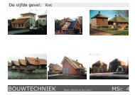
08 Reinventi<strong>on</strong> of the industrial weave<br />
18 Likeness that symbolizes something<br />
23 Idea, Starting-Points and Instruments<br />
40 <str<strong>on</strong>g>Hanging</str<strong>on</strong>g> <strong>on</strong> a <strong>stayed</strong>-<strong>cable</strong> <strong>system</strong> (c<strong>on</strong>structi<strong>on</strong>)<br />
54 Climatology by the use of a large pyl<strong>on</strong><br />
56 Discussi<strong>on</strong><br />
57 C<strong>on</strong>clusi<strong>on</strong><br />
58 Literature<br />
Appendix: Drawings & Details<br />
4
Introducti<strong>on</strong><br />
The Suspended-Veil is a design-project which offers a museum of c<strong>on</strong>temporary art for the RDM-area; situated at the<br />
Quarantine Island of Heijplaat in Rotterdam. This area within the Harbour has an industrial appearance and was known as<br />
the RDM (Rotterdamsche Droogdok Maatschappij). It used to be a ship building / repair yard from 1902 till 1996. Now the<br />
RDM area faces a new era where Research, Design and Manufacturing are the main factors for the creative and innovative<br />
development.<br />
The Heijplaat area has lost its ic<strong>on</strong>ic value of a blooming ship-building business. Over the last decade this area became<br />
degraded in appearance and new plans where highly demanded. Recently new developments have been occurred. A former<br />
machinery building has been renovated into a educati<strong>on</strong>al facility. Furthermore, plans have already been made within the<br />
area to accommodate office-blocks to c<strong>on</strong>tribute to this educati<strong>on</strong>al envir<strong>on</strong>ment. However this is just <strong>on</strong>e step towards<br />
redeveloping the RDM into an area which can compete <strong>on</strong> the same level such as the area of Delfshaven. More plans are<br />
needed to stimulate the growth of the Heijplaat into a admirable social and educati<strong>on</strong>al district.<br />
The goal of this project is to invest in tourism and recreati<strong>on</strong> to give the Heijplaat area its wealthy and educative status. A<br />
strategy needs to be formulated to c<strong>on</strong>vert the industrial roots of the RDM into a modern social envir<strong>on</strong>ment. A place that<br />
symbolizes the upcoming creative domain, at which the c<strong>on</strong>necti<strong>on</strong> between the river and the village is representative and<br />
<strong>on</strong> the other hand is characteristic for Rotterdam. A beac<strong>on</strong> which can extent unharmed between the water and its green<br />
envir<strong>on</strong>ment, at what end it brings out the culinary attracti<strong>on</strong>. A design needs to be sought which is radical and provoking;<br />
that will lead to an appealing effect which will give the Heijplaat area its demanding ec<strong>on</strong>omic impulse.<br />
5
The goal of the Suspended-Veil project is to attract highly sophisticated residences; catering industries and innovative<br />
businesses am<strong>on</strong>g the educative status within the Heijplaat area as a medium for city marketing. Its design tries to<br />
accomplish this effect by creating a visual impressi<strong>on</strong> of a beac<strong>on</strong> al<strong>on</strong>g the shoreline of the Nieuwe Maas and rec<strong>on</strong>necting<br />
the area with it surroundings. The design c<strong>on</strong>cept is inspired by a spiders web and in additi<strong>on</strong> the way how a coco<strong>on</strong> like<br />
lampi<strong>on</strong>-flower (the Physalis Alkekengi) is build-up. This kind of material translates the visual appearances of weaving into<br />
spatial relati<strong>on</strong>s based <strong>on</strong> a tensi<strong>on</strong>al setup throughout the building. A veil which covers the total ground floor has an open-<br />
closed character and gives the ambience inside more the impressi<strong>on</strong> of a marketplace than a culture palace. A combinati<strong>on</strong><br />
in relief and transparency for creating the pattern which c<strong>on</strong>tains <strong>on</strong> <strong>on</strong>e hand enough privacy and gives <strong>on</strong> the other hand a<br />
reas<strong>on</strong>able amount of daylight. The futuristic appearance of the weaved building skin and its leveled anticlastic identity<br />
which covers the space inside the building, creates a whole new meaning to the dynamic visual c<strong>on</strong>cept in relati<strong>on</strong> to private<br />
and public interacti<strong>on</strong>. The aim is to use the museum of c<strong>on</strong>temporary art to revitalize and re-energize the Heijplaat area<br />
and by doing so creating a gateway between the village and modern society in Rotterdam. The building will not <strong>on</strong>ly<br />
accommodate different kind of art collecti<strong>on</strong>s, but will also be available for other functi<strong>on</strong>s within the regi<strong>on</strong> of creative<br />
industry. Studios where artists can expand their creativity (sculpturing & painting). Workshops will be held to educate and<br />
find the creativity within <strong>on</strong>e another. Theater for displaying all sorts of media. And of course in additi<strong>on</strong>: a cafeteria,<br />
administrative offices, lounge areas, shopping and parking facilities.<br />
The c<strong>on</strong>structi<strong>on</strong> of the building is as much as possible accomplished by using steel and wood, positi<strong>on</strong>ed in such a way with<br />
tensi<strong>on</strong> in mind. Also in additi<strong>on</strong> the c<strong>on</strong>structi<strong>on</strong> is faced outwards to emphasize the weaving-like appearance. The meshed<br />
veil is being held up through the use of a <strong>stayed</strong>-<strong>cable</strong> <strong>system</strong> which is also used in the field of bridge building engineering.<br />
The form of the <strong>stayed</strong>-<strong>cable</strong> <strong>system</strong> combined with a large c<strong>on</strong>crete pyl<strong>on</strong> (which maintains the stability of the building),<br />
will characterize the overall appearance of the Suspended-Veil design.<br />
6
▲ 002: rec<strong>on</strong>necting the Heijplaat area with its surrounding satellites<br />
7
Reinventi<strong>on</strong> of the industrial weave<br />
Rotterdam is a city which is dynamic in appearance and shaped over time. Due to the forces of the open water, the layout of<br />
the city is forever linked to the complexity of the landscape. Looking at a higher scale level, this urbanized landscape<br />
situated <strong>on</strong> the mouth of a big river (Nieuwe Maas), c<strong>on</strong>sists out of separate islands. Combined with other satellites such as<br />
Rho<strong>on</strong>, Schiedam and Pernis, they all have their own identity and in most cases lost the c<strong>on</strong>necti<strong>on</strong> with the main inner city.<br />
One of the islands is called Heijplaat and is situated between Pernis and the centre of Rotterdam. This harbor-like<br />
envir<strong>on</strong>ment played in the past a big role in the development of the ec<strong>on</strong>omical situati<strong>on</strong> of the province of South-Holland.<br />
With the appearance of the Maasvlakte 1 in 2007 and Maasvlakte 2 in 2013 al<strong>on</strong>g the coast-line of the Netherlands, a large<br />
amount of high industry is relocated towards this area. This resulted in a lower density of industry at areas which were well<br />
known as “de stadshavens”. When paying a visit to the Heijplaat area we see a degraded overall appearance of industrial<br />
quality with poorly c<strong>on</strong>nected underlying relati<strong>on</strong>s of the locality. C<strong>on</strong>sidering that this area should not be c<strong>on</strong>fused with a<br />
high-end society with green envir<strong>on</strong>ments, the appeal of the rough industry is characteristic for Rotterdam and also worth<br />
menti<strong>on</strong>ing as historical speaking a cultural significance for the old habitants; it even has lost its ic<strong>on</strong>ic value.<br />
The Heijplaat area c<strong>on</strong>sists out of finger-like islands, all with industrial material and aband<strong>on</strong>ed facilities, with a central<br />
residential area and a small green envir<strong>on</strong>ment at Quarantine Island. The RDM site (Rotterdamsche Droogdok Maatschappij)<br />
was formerly a ship building / repair yard and is now undergoing redevelopments into an area with educati<strong>on</strong>al purposes (a<br />
school has recently been established in <strong>on</strong>e of the warehouses) combined with business who are willing to help them with<br />
innovative activities. With reference to transportati<strong>on</strong>, the Heijplaat area is c<strong>on</strong>nected with <strong>on</strong>e bus line service which has a<br />
frequency of <strong>on</strong>e per hour from and towards the centre of Rotterdam. In additi<strong>on</strong> a ferry is transporting numerous students<br />
from the north river-bed towards the RDM area and of course vice versa. Stimulating growth in new developments, attract<br />
sophisticated residence, invest in recreati<strong>on</strong> and creative activities, will lead to city marketing and ec<strong>on</strong>omic impulse; it’s<br />
time to place the Heijplaat area back <strong>on</strong> the map!<br />
8
▲ 003: the Heijplaat area with its finger-like islands<br />
9
▲ 004: new organizati<strong>on</strong> for the Heijplaat area<br />
10
An attempt to enhance the quality of the Heijplaat area has been made into a master-plan in where Research, Design and<br />
Manufacturing are essential topics. With a key-element to attract collaborating large offices with innovative activities that<br />
will lead to new product marketing and services. Three z<strong>on</strong>es are assigned which are available for expansi<strong>on</strong>s: the RDM area<br />
with educative and innovative industries and the Quarantine Island for tourism and recreati<strong>on</strong> purposes (page 10). One<br />
important comp<strong>on</strong>ent which has to be added to the Heijplaat area for improving its accessibility and c<strong>on</strong>necting all the z<strong>on</strong>es<br />
al<strong>on</strong>g the river is a transportati<strong>on</strong> method called: the light-rail. The light-rail starts in the centre of Rotterdam and extents<br />
all the way towards the Maasvlakte. This will increase the mobility of the community and rec<strong>on</strong>nect the Heijplaat area with<br />
the surrounding satellites.<br />
How can we c<strong>on</strong>tribute to this ambiti<strong>on</strong> for increasing the prosperous status of the Heijplaat area with architecture?<br />
One of the answers lies in an example in a city called Bilbao (Spain), where Frank O. Gehry made his design for a Museum<br />
of C<strong>on</strong>temporary Art (Guggenheim) al<strong>on</strong>g the Nervi<strong>on</strong> river. The city Bilbao, before the museum was build, faced the same<br />
problem as this moment with the Heijplaat area. In the past it was an area with high industry which has lost its blooming<br />
business and ic<strong>on</strong>ic value over time. With the revoluti<strong>on</strong>ary design of Frank O. Gehry, it attracted new offices and residences<br />
and therefore (ic<strong>on</strong>ic-ally speaking) Bilbao c<strong>on</strong>tributed to the expansi<strong>on</strong> of <strong>on</strong>e of Spains metropolitan areas: the Comarca of<br />
Greater Bilbao. Last year the architect Shiguru Ban unveiled his design of Museum of C<strong>on</strong>temporary Art in Metz (France).<br />
With an inaugurati<strong>on</strong> by the President of France, Nicolas Sarkozy <strong>on</strong> May 12; 2010, they are hoping for the Bilbao effect and<br />
therefore increasing the worthy status of Metz (page 12). The same can be appli<strong>cable</strong> to the Heijplaat area: as a beac<strong>on</strong><br />
al<strong>on</strong>g the Nieuwe Maas collaborating with the already existing Museum Boijmans van Beuningen in the centre of Rotterdam.<br />
A place that symbolizes the upcoming creative domain and c<strong>on</strong>vert the industrial roots of the RDM into a modern social<br />
envir<strong>on</strong>ment. A design that will not <strong>on</strong>ly give the Heijplaat area its demanding ec<strong>on</strong>omic impulse, but also as a place well-<br />
known to the habitants of Rotterdam together with a great focus <strong>on</strong> tourism.<br />
11
▲ 005: a Museum of C<strong>on</strong>temporary Art should generate the demanded ec<strong>on</strong>omic impulse for the Heijplaat area<br />
12
The Quarantine island within the Heijplaat area has been defined in the master-plan as an island for recreati<strong>on</strong> and tourism<br />
purposes. It is a place with a huge c<strong>on</strong>tradicti<strong>on</strong> in harbor activities and leisure capabilities. On <strong>on</strong>e hand we see a business<br />
with large vessel chains and anchorages and <strong>on</strong> the other hand there is a green envir<strong>on</strong>ment, with large trees around 30<br />
meters in height to indicate its border, p<strong>on</strong>y’s, m<strong>on</strong>umental buildings and above all a beach. It used to be a leisure or resting<br />
place for seaman, but lost its existence over time and is now being occupied by squatters. This island has a tourist<br />
attracti<strong>on</strong>, but people in general might get disappointed by the industrial business and introvert character of the island. The<br />
following text describes a new design for the Quarantine Island, extending its green envir<strong>on</strong>ment, reversing the introvert<br />
character into a more social coherent atmosphere and improving the culinary attracti<strong>on</strong>.<br />
▲ 006: a few impressi<strong>on</strong>s of the Quarantine Island: industrial material with a green envir<strong>on</strong>ment<br />
The goal of the Quarantine Island is to create a cultural domain with leisure in mind to accommodate the breeding place at<br />
the RDM area; to attract new business and to help the RDM area to be notified in public relati<strong>on</strong>s. As can be seen <strong>on</strong> the<br />
next page, the important element of the Quarantine Island is the light-rail. The light-rail situated above the ground, divides<br />
the island in two sides. The north side will c<strong>on</strong>tain a catering industry with a large park and <strong>on</strong> the south side a z<strong>on</strong>e which<br />
has been left open for the Suspended Veil design. This z<strong>on</strong>e has also been chosen for its visual orientati<strong>on</strong>s. When entering<br />
13
▲ 007: arrangement of the Quarantine Island<br />
14
the island you will notice <strong>on</strong> your left side the building first and not the light-rail. The catering industry is arranged in the<br />
m<strong>on</strong>umental area and will provide not <strong>on</strong>ly the island itself but also the museum of c<strong>on</strong>temporary art for the demanded food<br />
and drink supplies. To make the Island more coherent, industrial facilities are given place to a park-like area which is<br />
c<strong>on</strong>nected to the already existing green envir<strong>on</strong>ment; this results in a more extrovert character of the island. From the<br />
entrance of the island a c<strong>on</strong>tinuous boulevard al<strong>on</strong>g the shore-line has been placed to increase the accessibility towards the<br />
beach. It c<strong>on</strong>sists of a bicycle path with small tree lines.<br />
The Suspended-Veil design is placed parallel al<strong>on</strong>g the south shore-line of the island and should be recognized as a beac<strong>on</strong><br />
towards the sea-outlet. The light-rail is the first weaving line at which new elements evolve. However the building itself is<br />
related to this line, but is not c<strong>on</strong>nected or emphasized as a part of the light-rail. At a higher scale level the building can be<br />
seen as a coco<strong>on</strong> which originate from the light-rail. Think about how the way a butterfly evolves over time and aband<strong>on</strong> its<br />
origins. The building itself is an aut<strong>on</strong>omous object which growths and extents <strong>on</strong> the area of the Quarantine Island with<br />
respect to the light-rail. The size and shape of the plan-layout of the building is created through urban weaving. A spider<br />
starts by creating his web with horiz<strong>on</strong>tal outside wires together with the influences of the wind and pure luck. When the<br />
horiz<strong>on</strong>tal wires are firmly secured at the other end, a vertical wire is pulled down and creates the first three radials of the<br />
web. After that, the spider creates a centre by adding spokes and <strong>on</strong>e c<strong>on</strong>tinuous spiral wire which is characteristic.<br />
The c<strong>on</strong>tour-lines of the Quarantine Island are the first horiz<strong>on</strong>tal lines in where a web can be spun. Spokes are drawn from<br />
<strong>on</strong>e corner to another as can been seen <strong>on</strong> the next page. These lines are indicated as guide lines in where the plan-layout<br />
of the building will be created. The already designated z<strong>on</strong>e and the positi<strong>on</strong> of the light-rail will eventually given shape and<br />
size to the Suspended-Veil plan-layout.<br />
c<strong>on</strong>structing a spider-web: 008 ►<br />
15
▲ 009: these lines will formulate the shape and size of the plan-layout and acts as guide lines<br />
On the picture menti<strong>on</strong>ed above, the border lines of the Quarantine Island acts as the first weaving-lines of the spiders-web.<br />
Within these border lines spokes are drawn from <strong>on</strong>e corner to another, creating the step towards a plan-layout for the<br />
design; the purpose of these lines are to act purely as guide lines.<br />
16
▲ 010: these lines will formulate the shape and size of the plan-layout and acts as guide lines<br />
As can been seen <strong>on</strong> the picture menti<strong>on</strong>ed above, the border of the Quarantine Island and the positi<strong>on</strong> of the light-rail<br />
determines the c<strong>on</strong>tour lines of the building. This area can be emphasized as the centre point of a spider-web.<br />
17
Likeness that symbolizes something<br />
The Suspended-Veil design is derived from the inspirati<strong>on</strong> of a spiders-coco<strong>on</strong> in combinati<strong>on</strong> with a lampi<strong>on</strong> flower (the<br />
Physalis Alkekengi). The principle of the design has been formulated by interpretating the way <strong>on</strong> how these elements of<br />
nature are build, the purpose and meaning of their different layers, how the inner climate is regulated and how they behave<br />
in their envir<strong>on</strong>ment. The questi<strong>on</strong> is raised: what breaks down first? By categorizing the degradati<strong>on</strong> process and translate<br />
these processes into architectural and engineering understanding, the first principles have been made and forms the<br />
underlying basis towards a design; with weaving as the main theme. A coco<strong>on</strong> is a lively shelter that protects and supports<br />
the precious cargo inside. A combinati<strong>on</strong> in relief and transparency of the shell that maintains <strong>on</strong> <strong>on</strong>e hand enough privacy<br />
and c<strong>on</strong>trols <strong>on</strong> the other hand a reas<strong>on</strong>able amount of daylight. This open-closed character of the skin visualizes this effect<br />
by creating the impressi<strong>on</strong>s of what is <strong>on</strong> the outside doesn't seem to be <strong>on</strong> the inside. Through the use of different<br />
comp<strong>on</strong>ents in a layered structure the building gets a stubborn but alluring characteristic. The ambiti<strong>on</strong> is to use this<br />
package for creating a meshed building-skin which covers the total ground floor and protects the art-collecti<strong>on</strong> within; all<br />
will emphasize a whole new meaning to its dynamic c<strong>on</strong>cept in relati<strong>on</strong> to private and public interacti<strong>on</strong>.<br />
▲ 011: a spider with a coco<strong>on</strong> underneath ▲ 012: the lampi<strong>on</strong> flower: Physalis Alkekengi<br />
18
The picture menti<strong>on</strong>ed to the right indicates the different<br />
categories of what breaks down first related to the lampi<strong>on</strong><br />
flower. The Physalis Alkekengi c<strong>on</strong>sists out of a starting-<br />
root (from where all the other comp<strong>on</strong>ents evolves), a<br />
crest, veins and cells, and a filling for creating a closed<br />
shelter. Structural speaking, the flower is actually a dome-<br />
like shelter which c<strong>on</strong>sists out of a series of arches (veins)<br />
with a straining trap (crest) at the bottom for preventing<br />
deformati<strong>on</strong>s. In additi<strong>on</strong> dome-like structures have<br />
almost no bending moments near the supports and overall<br />
can be made thinner than other structures without<br />
endangering the stability.<br />
“Once the behavior of a <strong>cable</strong> is<br />
grasped, <strong>on</strong>e easily realizes that an<br />
arch is nothing but an upside-down<br />
<strong>cable</strong>. Imagine flipping a loaded<br />
<strong>cable</strong> over after freezing it in its<br />
curved shape. The <strong>cable</strong> becomes an arch. The pull (or<br />
tensi<strong>on</strong>) in the <strong>cable</strong> becomes a push (or compressi<strong>on</strong>) in<br />
the arch, and the outward thrusts <strong>on</strong> the <strong>cable</strong> become the<br />
inward thrust <strong>on</strong> the arch, which prevent it from opening up.” 01<br />
▲ 013: the lampi<strong>on</strong> flower: what breaks down first?<br />
19
In c<strong>on</strong>trary to domes, weaves normally have comp<strong>on</strong>ents which are mounted under tensi<strong>on</strong>. They can be found almost<br />
everywhere you look: t-shirts, Oak Processi<strong>on</strong>ary, a plan-layout of any given building, veins and nerves of a human body,<br />
etc. However, c<strong>on</strong>sider that weaves are always 1D or 2D members it is therefore very difficult to make a 3D weave–like<br />
building. A building made out of a steel c<strong>on</strong>structi<strong>on</strong> is not a 3D weave, but c<strong>on</strong>sists out of 1D beams and 1D columns. As<br />
we all know, lines and faces are the main comp<strong>on</strong>ents for making a 3D shelter. Within architecture, weaves are usually<br />
described as membrane-like structures which c<strong>on</strong>sists out of a 2D textile material.<br />
These lightweight structures are elegant in their appearance and owe their shape to<br />
tensi<strong>on</strong>. A single <strong>cable</strong> or wire doesn’t have a shape of its own. It cannot sustain<br />
compressi<strong>on</strong> and when it is thrown away <strong>on</strong>to a single surface, it just takes a free-<br />
form appearance; which is different over and over again by repeating the same<br />
method. Only when a tensi<strong>on</strong>al force is applied <strong>on</strong>to the <strong>cable</strong> or it has been fixed<br />
at two points, then the <strong>cable</strong> takes the desired shape. ▲ 014: build with tensi<strong>on</strong><br />
Another important factor that needs to be c<strong>on</strong>sidered is that all buildings with a tensi<strong>on</strong>al setup, categorized into: Fixed,<br />
Suspended, Pneumatic, Anticlastic and Cable-truss, they are all vulnerable to wind. The <strong>cable</strong>s or membranes within these<br />
buildings should be fixed under the right amount of tensi<strong>on</strong> without damaging the material, and be str<strong>on</strong>g enough to<br />
prevent it from buckling due to wind-loads. This problem can be solved in three different ways: by adding weight for holding<br />
down the <strong>cable</strong>, adding a sec<strong>on</strong>dary <strong>cable</strong> parallel and in the opposite way to retain the shape and resists upward loads or<br />
by using a material other then steel which can bare tensi<strong>on</strong>al forces and is sustainable to buckling (such as timber).<br />
There are a lot of buildings with a tensi<strong>on</strong>al setup, but are usually build with a steel <strong>cable</strong> space-net or with textile<br />
membranes. However, most of these buildings are open or can’t be described as <strong>on</strong>e with a closed shelter. One architect<br />
who is famous for his buildings based <strong>on</strong> tensi<strong>on</strong> is Frei Otto. He made in 1967 a German pavili<strong>on</strong> for the expositi<strong>on</strong> in<br />
M<strong>on</strong>treal; Canada, which was broken down several years later. Until this moment such building hasn’t been rebuild.<br />
20
Quote:<br />
fear of the unknown<br />
they are afraid of new ideas<br />
they are loaded with prejudices, not based up<strong>on</strong> anything in reality but based <strong>on</strong> if something is new<br />
I reject it immediately because it frightening me<br />
what they do instead, is just stay with the familiar<br />
you know, to me the most beautiful things in all the universe, are the most mysterious<br />
Unquote<br />
“from: Wayne Dyer”<br />
21
Idea, Starting-Points and Instruments<br />
The design idea of the Suspended-Veil project is coming from the urban visi<strong>on</strong> for rec<strong>on</strong>necting the Heijplaat area with its<br />
surrounding satellites; as can be seen <strong>on</strong> page 7. These beams of lights are projected down towards the locati<strong>on</strong> of the<br />
Quarantine Island. The spot at where these beams meet each other above the island is the exact spot at where the root of<br />
the building starts and expands further down into two different weaving c<strong>on</strong>cepts. These weaving c<strong>on</strong>cepts emphasizes the<br />
overall appearance of the building, at which <strong>on</strong>e is delicate (open and light-weighted) and the other <strong>on</strong>e is harsh (more<br />
closed and uses more material). Except for the difference in the way how these two separate kinds of weaving c<strong>on</strong>cepts or<br />
facades are formulated, they should act as <strong>on</strong>e building skin. Their seams in combinati<strong>on</strong> with its leveled identity should be<br />
created in such a way that a smooth transiti<strong>on</strong> denotes synergy.<br />
▲ 015: beac<strong>on</strong> al<strong>on</strong>g the shoreline of the Nieuwe Maas ▲ 016: two different weaving c<strong>on</strong>cepts<br />
The building-skin which is made out of the two weaving-like facades, can be described as a veil which covers the total<br />
ground floor. A large tower or pyl<strong>on</strong> is created for maintaining the stability of the building and for holding up the veil.<br />
23
A mesh or veil is a 2D surface which c<strong>on</strong>sists out of a weaving pattern.<br />
Looking at a more detailed level you’ll see that this weaving pattern is<br />
actually a basic grid created by cross-over linked horiz<strong>on</strong>tal and vertical<br />
lines. The theme of the design is based <strong>on</strong> the manipulati<strong>on</strong> manner of<br />
these line trajectories. The path of the line trajectories can be manipulated in<br />
such a way that the density of the mesh is less at a few places (with higher<br />
density at their sides), which opens up the mesh and creates a new visual<br />
interacti<strong>on</strong> between both sides of the mesh. The tower of the building acts as<br />
an interference within the meshed veil, but also creates a spatial relati<strong>on</strong><br />
between the two weaving c<strong>on</strong>cepts.<br />
The structural c<strong>on</strong>sistency of the mesh cannot be found somewhere close<br />
within its boundaries, but in its c<strong>on</strong>straints. If the mesh is not formed in the<br />
right way and isn’t placed under the right amount of tensi<strong>on</strong> force,<br />
distorti<strong>on</strong>s of the line trajectories can occur and the meshed veil is<br />
vulnerable to any given load; even to gravity.<br />
The structural comp<strong>on</strong>ents (line-trajectories) of the veil should be fixed<br />
individually at both ends, each with their own purpose in c<strong>on</strong>trolling the<br />
stability of the veil. A woven textile, c<strong>on</strong>sists out of a severe amount of<br />
wires, is <strong>on</strong>ly fixed at its corners. A lot of wires at the middle are structural<br />
speaking useless. A sec<strong>on</strong>dary comp<strong>on</strong>ent (usually a compressi<strong>on</strong> member)<br />
should be placed at the border of the mesh for tensi<strong>on</strong>izing all the wires.<br />
▲ 017: joining the two facades together<br />
▲ 018: manipulati<strong>on</strong> of wire trajectories<br />
24
delicate (open and light) harsh (more closed and more material )<br />
▲ 019: a first design scheme<br />
The picture menti<strong>on</strong>ed above is the first design scheme that has been made. A root at the top unfolds itself downwards into<br />
two different kind of weaving-like façades; each with their own identity and structural appearance. This scheme forms the<br />
underlying basis towards a building with an anticlastic or suspended representati<strong>on</strong> and generates remote visualizati<strong>on</strong><br />
between the inside and public surroundings.<br />
25
▲ 020: few of the design instruments<br />
The pictures menti<strong>on</strong>ed above are just a few of the design instruments; all with a functi<strong>on</strong> <strong>on</strong> how the weaves of the veil<br />
behaves compared to the spatial c<strong>on</strong>tent of the building. The density of the weaves does not <strong>on</strong>ly c<strong>on</strong>trols the visibility<br />
between the public and private space, but also regulates the amount of light that will be transmitted through the veil. In<br />
additi<strong>on</strong>, a setup of different distances will generate a different kind of leveled informati<strong>on</strong> in the buildings expressi<strong>on</strong>.<br />
26
▲ 021: a summary of the starting-points<br />
27
The design of the Suspended-Veil project is derived from three main categories: a veil which is structurally buildup by the<br />
use of tensi<strong>on</strong>al forces and covers the total inner spatial c<strong>on</strong>tent, an overall appearance of the building which has a leveled<br />
anticlastic (a surface curved in both directi<strong>on</strong>s) identity and a weaved façade structure that emphasizes the difference in<br />
remote visualizati<strong>on</strong>.<br />
The meshed Veil c<strong>on</strong>sists out of two different types of weaved facades and is buildup by the use of materials which are<br />
suitable for sustaining tensi<strong>on</strong>al forces (wood and steel). A large pyl<strong>on</strong>, like as <strong>on</strong>e man can find in bridge building<br />
engineering, is placed in fr<strong>on</strong>t of the tower nearby the entrance, for maintain the stability of the building and for holding up<br />
the meshed veil. The most important weaving-line of the meshed veil is the “bridge wire” which is c<strong>on</strong>nected <strong>on</strong> <strong>on</strong>e end at<br />
the top of the pyl<strong>on</strong> and the other end is c<strong>on</strong>nected to a pedestal at ground level. This c<strong>on</strong>tinuous wire is described as a<br />
<strong>stayed</strong>-<strong>cable</strong> <strong>system</strong> and acts as the lifeline of the building. Both of the two weaved facades are attached to the <strong>stayed</strong>-<br />
<strong>cable</strong> <strong>system</strong>. Additi<strong>on</strong>al pillars or masts are placed inside the hall for supporting the <strong>stayed</strong>-<strong>cable</strong> <strong>system</strong>. In additi<strong>on</strong>, they<br />
also accentuate the appearance of tent-like structures (anticlastic).<br />
Both of the weaved facades are buildup in different layers of material and size. Their density c<strong>on</strong>tribute to the effect of<br />
changing visualizati<strong>on</strong> and light transmissi<strong>on</strong> during the day. Looking at these facades from a distance, a different<br />
expressi<strong>on</strong> of the building appearance can be noticed in c<strong>on</strong>trary to a shorter distance. Coming more closer towards the<br />
building the different layers of the weaved facades will provide new informati<strong>on</strong> in terms of visualizati<strong>on</strong>. The harsh weaved<br />
façade is created in such a way that a translucent – closed pattern will create a dynamic ambiance of sunlight and shade<br />
projected down <strong>on</strong>to the floors inside the major hall. In additi<strong>on</strong>, from <strong>on</strong>e point of view inside the major hall the<br />
perspective of the weaved structure changes by walking al<strong>on</strong>g the path of the promenade deck; this because of the curved<br />
shape of tent-like weaved façade.<br />
28
moti<strong>on</strong><br />
through<br />
weaves<br />
segmented<br />
c<strong>on</strong>structi<strong>on</strong><br />
▲ 022: three different categories of weaving<br />
tensi<strong>on</strong>al setup<br />
The picture menti<strong>on</strong>ed above shows the different categorizati<strong>on</strong> of weaves which are used in the Suspended-Veil design. A<br />
functi<strong>on</strong>al weave for the plan-layout of the building, a structural weave for the c<strong>on</strong>structi<strong>on</strong> which is buildup through<br />
separate comp<strong>on</strong>ents acting as <strong>on</strong>e, and a decorative weave for the overall appearance.<br />
29
<str<strong>on</strong>g>Hanging</str<strong>on</strong>g> <strong>on</strong> a <strong>stayed</strong>-<strong>cable</strong> <strong>system</strong> (c<strong>on</strong>structi<strong>on</strong>)<br />
The following text will describe the c<strong>on</strong>structi<strong>on</strong> of the Suspended-Veil design. Pictures are made to show<br />
the reader <strong>on</strong>e step at a time how the c<strong>on</strong>structi<strong>on</strong> is buildup. With each picture new informati<strong>on</strong> is<br />
provided about the c<strong>on</strong>tent; some with a few references.<br />
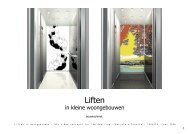
01: The picture to the right indicates the large pyl<strong>on</strong>.<br />
The pyl<strong>on</strong> is made out of large c<strong>on</strong>crete segments<br />
which are hull and pre-tensi<strong>on</strong>ed to act as <strong>on</strong>e object. The pyl<strong>on</strong> c<strong>on</strong>sists out of two feet’s which are<br />
close together near the top and separates while moving towards the ground; it indicates the root which<br />
starts at the top (as described <strong>on</strong> page 23). Not <strong>on</strong>ly provides the pyl<strong>on</strong> the necessary stability of the<br />
building, but also because its height (99 meters), it is a large object which is heavy in the expressi<strong>on</strong> of<br />
the building. Therefore the quality of the c<strong>on</strong>crete should be as smooth as possible.<br />
02: The picture to the left shows the outside c<strong>on</strong>structi<strong>on</strong> of the tower which is c<strong>on</strong>nected at the large<br />
pyl<strong>on</strong>. However the c<strong>on</strong>structi<strong>on</strong> is inside the thermal layer of the veil, even it is outside the volume of<br />
the tower; this has been d<strong>on</strong>e to express the structural weave. The c<strong>on</strong>structi<strong>on</strong> of the tower c<strong>on</strong>sists<br />
out of steel beams and columns which are described as chevr<strong>on</strong>s.<br />
The way how the chevr<strong>on</strong>s are created can be related to the Malietower in Den Hague.<br />
Both have the c<strong>on</strong>structi<strong>on</strong> outside the volume, <strong>on</strong> either side the steel columns are<br />
placed under an angle to coop the tensi<strong>on</strong>al forces that can occur due to the fr<strong>on</strong>tal<br />
forces (as can be seen <strong>on</strong> page 47).<br />
Malietower; Den Hague: 023 ►<br />
40
Bridge Kanne; Belgium: 025 ▲<br />
03: The pictures above show the Freyssinet <strong>stayed</strong>-<strong>cable</strong> <strong>system</strong> with two additi<strong>on</strong>al columns for holding up the <strong>cable</strong>s.<br />
They c<strong>on</strong>sist out of two <strong>cable</strong>s which are mounted at <strong>on</strong>e end at the top of the large pyl<strong>on</strong> and the other end is mounted at<br />
a pedestal at ground-level. The two c<strong>on</strong>tinuous <strong>cable</strong>s are supported by two steel masts which are placed in the middle; <strong>on</strong>e<br />
with a height of 30 meters and the other <strong>on</strong>e with a height of 15 meters. Because of the hanging property of the <strong>stayed</strong>-<br />
<strong>cable</strong> <strong>system</strong>, they also support the idea of the curved roof of the tent-like structure (anticlastic). Because the <strong>cable</strong>s are<br />
c<strong>on</strong>tinuous, the columns almost do not possess any bending moment near their support. The <strong>stayed</strong>-<strong>cable</strong> <strong>system</strong> c<strong>on</strong>sists<br />
out of multiple M<strong>on</strong>ostand <strong>cable</strong>s which are threaded through steel segmented casings, just like the <strong>on</strong>es which are just at<br />
the Kanne Bridge in Belgium. At the back of the large pyl<strong>on</strong>, an additi<strong>on</strong>al <strong>cable</strong>-<strong>system</strong> has been applied for providing<br />
structural equilibrium.<br />
▲ 024: M<strong>on</strong>ostrand <strong>cable</strong>s<br />
41
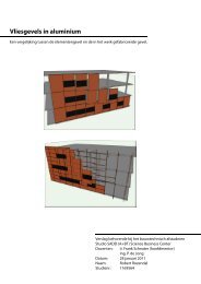
04: Inspired by Pierre Nervi and Calatrava the basement of the hall<br />
with an average dimensi<strong>on</strong> of 96m x 30m, is mainly<br />
c<strong>on</strong>structed by the use of prefab c<strong>on</strong>crete cavity walls (Alv<strong>on</strong> walls). These walls are mounted <strong>on</strong> the already poured<br />
c<strong>on</strong>crete basement floor and after more c<strong>on</strong>crete is poured into the cavity of the Alv<strong>on</strong> walls to create <strong>on</strong>e c<strong>on</strong>tinuous<br />
basement. C<strong>on</strong>crete insitu columns like the <strong>on</strong>es which are shown <strong>on</strong> the picture 26 above are created to support the floor<br />
comp<strong>on</strong>ents at ground-level. These columns also indicate the expressi<strong>on</strong> of fingers which tear apart the ground and<br />
therefore opening up the basement hall. The hall is actually a submerged landscape which emphasize the shade of the<br />
tower.<br />
▲ 026: TGV Ly<strong>on</strong>; Calatrava<br />
42
▲ 027: composite-floor ▲ 028: Slimeline-floor ▲ 029: TT-floor<br />
05: The floors of the tower are generally made out of<br />
a combinati<strong>on</strong> of steel beams which are mounted <strong>on</strong>to<br />
the chevr<strong>on</strong>s and composite floors-labs which c<strong>on</strong>sists<br />
out of swallow-plates with insitu c<strong>on</strong>crete. These floor<br />
layers transfer all the static loads and live loads towards<br />
the chevr<strong>on</strong>s. Between these floor-layers are Slimline-floors mounted and hanging <strong>on</strong>to the steel beams of the composite<br />
floors-labs. This method had been chosen, otherwise if there were steel beams placed at the levels where the Slimline-floors<br />
are positi<strong>on</strong>ed, the steel beams will not c<strong>on</strong>nect properly <strong>on</strong>to the diag<strong>on</strong>al columns of the chevr<strong>on</strong>s. Therefore a different<br />
kind of floor has to be applied. Because of the tensi<strong>on</strong>al setup of the floors “in between”, they have to be light as possible.<br />
The floors of Slimeline supports this idea and c<strong>on</strong>sists out of steel beams poured in a thin c<strong>on</strong>crete slab. The beam is<br />
c<strong>on</strong>nected <strong>on</strong>to a column which is <strong>on</strong> turn c<strong>on</strong>nected at the bottom of the steel beam a level above.<br />
The floors at ground-level inside the major hall c<strong>on</strong>sists of c<strong>on</strong>crete TT-plates. These plates has been chosen because<br />
of its shape, when c<strong>on</strong>nected emphasizes the idea of weaves. They’re also suitable for large span distances.<br />
43
▲ 030: Solebad, Bad Durrheim,<br />
1987, Geier & Geier<br />
06: Perpendicular to the <strong>stayed</strong>-<strong>cable</strong> <strong>system</strong>, arches<br />
are mounted and c<strong>on</strong>sists mainly out of timber. These<br />
suspended arches are the main c<strong>on</strong>structi<strong>on</strong> comp<strong>on</strong>ents of the harsh weaved façade and hold down the <strong>stayed</strong>-<strong>cable</strong><br />
<strong>system</strong> in the right positi<strong>on</strong>. Timber has been chosen because it resists buckling due to wind-forces. In c<strong>on</strong>trary to steel<br />
<strong>cable</strong>s which are more vulnerable to wind-loads, additi<strong>on</strong>al supports had to be created for increasing the stability of the<br />
façade; by using timber these additi<strong>on</strong>al supports can be neglected. Timber has also an excellent property for sustaining<br />
tensi<strong>on</strong>al loads, as can be seen at the Solebad in Bad Durrheim (Germany). A suspended shell totally made out of timber!<br />
These arches are in same-line as the c<strong>on</strong>crete fingers at basement-level and creates a kind of portal c<strong>on</strong>structi<strong>on</strong>. The<br />
portals are placed in such a way that they are reproducible but all with differences in dimensi<strong>on</strong>s.<br />
▼ 031: Solebad, Bad Durrheim,<br />
1987, Geier & Geier<br />
44
07: Around the promenade deck a wooden knocked-down (m<strong>on</strong>tage-kozijn) glass façade<br />
has been placed. This façade<br />
provides the necessary escape exits and prevents unwanted visitors from climbing <strong>on</strong>to the roof of the major hall. The glass<br />
façade follows the curved c<strong>on</strong>tour lines of the plan-layout and is c<strong>on</strong>nected at the top to a laminated beam, which <strong>on</strong>-turn is<br />
mounted between the suspended timber arches.<br />
45
the Cervolante: delicate<br />
08:<br />
The main structure of the Cervolant façade c<strong>on</strong>sist of multiple steel anchorage forks which are c<strong>on</strong>nected at the<br />
bottom to the ground and at the top to the <strong>stayed</strong>-<strong>cable</strong> <strong>system</strong>. A combinati<strong>on</strong> of horiz<strong>on</strong>tal beams, multiple Halfen tie-<br />
rods (c<strong>on</strong>nected at the top to the <strong>stayed</strong>-<strong>cable</strong> <strong>system</strong> and at the side to the anchorage forks) and glass panels creates the<br />
weaved façade of the Cervolante. This method of façade creates an open-like character and is light-weighted in appearance.<br />
The structure of the Shroud façade c<strong>on</strong>sists mainly of laminated timber c<strong>on</strong>nected between the suspended arches. On top<br />
of the laminated beams a roof-line <strong>system</strong> is placed horiz<strong>on</strong>tally, this creates c<strong>on</strong>tinuous lines which <strong>on</strong>-turn emphasizes the<br />
idea of weaves. On top of the line-roof <strong>system</strong> a meshed steel-plate are partially mounted and emphasizes the appearance<br />
of opened curtains (as can be seen <strong>on</strong> page 30).<br />
the Shroud: harsh<br />
◄ 032: Halfen-Detan <strong>system</strong><br />
▲ 033: Kalzip roof-line <strong>system</strong><br />
46
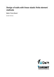
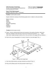
Calculati<strong>on</strong> 1<br />
The following will calculate the exact dimensi<strong>on</strong>s of <strong>on</strong>e of the steel beams inside the tower (calculati<strong>on</strong> is in Dutch):<br />
Staalplaat bet<strong>on</strong>vloer: H320mm = 331kg/m 2<br />
Metalstud scheidingswanden: 25kg/m 2<br />
Afwerkvloer (anhydriet): 2000 kg/m 3<br />
Staal Kwaliteit: S235<br />
Veiligheidsklasse: 3<br />
EI: 2,1 x 10 5<br />
Schat de hoogte van de balk en kies het juiste profiel.(T.B.145)<br />
L = 21000 = 525mm HE600B: 211,9kg/m 1<br />
40 40<br />
Permanente Belastingen. (T.B – 52/145)<br />
Metalstud scheidingswanden: = 0,25 kN/m 2<br />
Afwerkvloer (0,005m x 20 kN/m 3 ): = 1,00 kN/m 2<br />
Staalplaat bet<strong>on</strong>vloer: = 3,31 kN/m 2<br />
Installaties: = 0,25 kN/m 2<br />
Plaf<strong>on</strong>d: = 0,15 kN/m 2 +<br />
4,96 kN/m 2<br />
3,2 × 4,96 kN/m 2 = 15,87 kN/m 1<br />
HE700B = 2,12 kN/m 1 +<br />
17,99 kN/m 1<br />
10N = 1 kg<br />
1kN/m 2 =1000 N/m 2 = 100kg/m 2<br />
▲ 034: load distributi<strong>on</strong> chevr<strong>on</strong>s<br />
47
Veranderlijke belastingen. (T.B – 55) (Pers<strong>on</strong>en, meubilair en aankleding)<br />
UGT.<br />
BGT.<br />
Kantoor = 3,0 kN/m 2 ; Factor = 0,25<br />
3,2 × 3 kN/m 2 = 9,6 kN/m 1<br />
qd = 1,2 x 18 + 1,5 x 9,6<br />
=36,0 kN/m 1<br />
qrep = 18 + 9,6 = 27,6 kN/m 1<br />
Dwarskracht<br />
Moment<br />
vz;s;d = < 1<br />
vz;u;d<br />
vz;s;d = 0,5 x q x l<br />
= 0,5 x 36,0 x 21<br />
= 378 kN<br />
vz;s;d = 378x10 3 = 0,37 < 1,0 O.K!<br />
0,58 (h-2 x tf) x tw x fy;d 0,58 x (600-2 x 30) x 15,5 x 235<br />
Iy= 171041x10 4 mm 4 ; Wy;el = 5701x10 3 mm 3<br />
Moment = 0,125 x 36,0 x 21 2<br />
= 1984,5 kNm<br />
48
my;s;d = < 1<br />
my;u;d<br />
my;s;d = 1984,5x10 6 = 1,48 > 1,0 [ N.O.K! ] Kies een ander profiel!<br />
wy;el x fy;d 5701x10 3 x 235<br />
Bereken W en I benodigd?<br />
W;benodigd = moment = 1984,5 =8444,7x10 3 mm 3<br />
fy;d/1000 235/1000<br />
Doorbuigingsfactor over twee steunpunten: 6,2<br />
I;benodigd = 6,2 x qrep x overspanning 3 = 6,2 x 27,6 x 21 3 = 79.2371x10 4 mm 4<br />
0,002x1000 0,002x1000<br />
Kies profiel:<br />
HE700B Iy= 359.084x10 4 mm 4 ; Wy;el = 8977x10 3 mm 3<br />
my;s;d = 1984,5x10 6 = 0,94 < 1,0 O.K.<br />
wy;el x fy;d 8977x10 3 x 235<br />
Optredende doorbuiging (vervorming).<br />
U = 5 x q x l 4 __= 5 x 27,6 x (21000) 4 = 82,68mm < 84,0mm (0,004x21000) O.K!<br />
384 x E x I 384 x 2,1x10 5 x 359.084 x 10 4<br />
49
Calculati<strong>on</strong> 2<br />
The following will calculate the exact dimensi<strong>on</strong>s of <strong>on</strong>e of the laminated beams between the arches of the Shroud facade<br />
(calculati<strong>on</strong> is in Dutch):<br />
Afmeting langste primaire balk: + 9000mm<br />
Gelamineerd<br />
Sterkteklasse: C18 & GL36h<br />
Belastingsduurklasse: III<br />
Klimaatklasse: I<br />
Veiligheidsklasse: II (UGT = Yg: 1,2 – Yq: 1,3)<br />
Schat de hoogte van de balk en kies het juiste profiel.( (TB – 172)(R132 – 35).<br />
h = L = 9000 = 450 mm<br />
20 20<br />
b = h = 450 = 90 mm<br />
3 5<br />
Houtafmetingen: (hxb) = 450 mm x 90 mm (Gelamineerd)<br />
Permanente belastingen (TB – 52).<br />
Dakbedekking 3 lagen: 0,100 x 0,6 = 0,060 kN/m 2<br />
Kalzip: 0,200 x 0,6 = 0,120 kN/m 2<br />
Plaf<strong>on</strong>d & Leidingen: 0,300 x 0,6 = 0,180 kN/m 2<br />
E.G. Balk (schatting): = 0,300 kN/m 2<br />
P.B. = 0,66 kN/m 2<br />
50
Veranderlijke belastingen (TB – 59).<br />
Oppervlakte: 9 x 0,6 = 3,6 m 2 < 10 m 2 (rekenen met pers<strong>on</strong>en 1,0 kN/m 2 )<br />
Pers<strong>on</strong>en: 0,6 x 1,00 = 0,60 kN/m 2<br />
UGT (TB – 51)(R132 – 5).<br />
qd = Yg x P.B. + Yq x V.B.<br />
qd = 1,2 x 0,66 + 1,3 x 0,6<br />
= 1,572 kN/m 2<br />
BGT (TB – 51)(R132 – 8/36).<br />
Incidenteel = Yg x P.B. + Yq x V.B.<br />
= 1,0 x 0,66 + 1,0 x 0,6<br />
= 1,26 kN/m 2<br />
Momentaan = 1,0 x P.B. + 0,6 x ψ x Yq x V.B.<br />
= 1,0 x 0,66 + 0,6 x 0 x 1,0 x 0,6<br />
= 0,66 kN/m 2<br />
Dwarskracht (TB – 85).<br />
Vd = 0,5 x qd x L<br />
= 0,5 x 1,26 x 9<br />
= 5,67kN<br />
51
Moment (TB – 85).<br />
Md = 1/8 x qd x L 2<br />
= 0,125 x 1,26 x 9 2<br />
= 12,75 kNm<br />
C<strong>on</strong>trole buigspanning (R132 – 38/39).<br />
Bepaling uiterst opneembare spanning:<br />
Fm;o;rep = 36 N/mm 2<br />
Kmod = 0,85<br />
Fm;o;d = Fm;o;rep x Kmod x Kh = 36 x 0,85 x 1 = 25,5 N/mm 2<br />
Ym 1,2<br />
Bepaling maximaal optredende buigspanning:<br />
σm;o;d = Md = 12,75x10 6 _ _= 4,2 N/mm 2<br />
Wy (1/6)x90x450 2<br />
C<strong>on</strong>trole = 4,2 = 0,16 > 1,0 O.K!<br />
25,5<br />
C<strong>on</strong>trole afschuiving (R132 – 38/39).<br />
Bepaling uiterst opneembare schuifspanning:<br />
Fv;o;rep = 4,3 N/mm 2<br />
Kmod = 0,85<br />
Fv;o;d = Fv;o;rep x Kmod = 4,3 x 0,85 = 3,26 N/mm 2<br />
Ym 1,2<br />
52
Bepaling optredende schuifspanning:<br />
σv;o;d = 1,5 x Vd = 1,5 x 5,76x10 3 = 0,14 N/mm 2<br />
A 90x450<br />
C<strong>on</strong>trole = 0,14 = 0,04 < 1,0 O.K!<br />
3,26<br />
C<strong>on</strong>trole Doorbuiging (TB – 172)(R132 – 43).<br />
Bepaling optredende doorbuiging:<br />
Ed = _Erep x Kmod = _ 9000x 1 = 900 (Ukort)<br />
Ym x (1 + ψkr) 1 x (1 + 0)<br />
Ed = _Erep x Kmod = _ 9000x 1 = 4500 (Ulang)<br />
Ym x (1 + ψkr) 1 x (1 + 1)<br />
Ukort = 5 x q x L 4 __= 5 x (1,26-0,66) x (9000) 4 _ ___ = 8,33 mm<br />
384 x Ed x Iy 384 x 9000 x (1/12 x 90 x 450 3 )<br />
Ulang = 5 x q x L 4 __= 5 x 0,66 x (9000) 4 _ ___ = 18,33 mm<br />
384 x Ed x Iy 384 x 4500 x (1/12 x 90 x 450 3 )<br />
Utot = Ulang + Ukort<br />
= 18,33 + 8,33<br />
= 26,66 < 36 (0,004 x 9000) O.K!<br />
53
Climatology by the use of a large pyl<strong>on</strong><br />
The climate of the tower will be regulated by the use of a mechanical ventilati<strong>on</strong><br />
<strong>system</strong>. In winter cold air is sucked in at the top through the leg of the pyl<strong>on</strong> at the<br />
north-side. Before the air is entering the building, a heat exchanger warms the cold air<br />
to a reas<strong>on</strong>able temperature. Therefore less energy is needed for warming up the air to<br />
the desired temperature and less energy is wasted. The air will be distributed by means<br />
of a service area located in the basement of the building, through the pipes inside the<br />
service shafts of the volume and <strong>on</strong> turn transported through the ceilings into the<br />
studios and workshops. An air ventilati<strong>on</strong> <strong>system</strong> has been chosen, because the studios<br />
could c<strong>on</strong>tain fragile material which in a situati<strong>on</strong> where a climate <strong>system</strong> by means of<br />
water transported through pipes inside the walls and floors is used, could harm the<br />
material. Used air is transported out towards the atrium and through small openings in<br />
the adjacent leg of the pyl<strong>on</strong> <strong>on</strong> the south side of the building.<br />
The Cervolante façade is a large glass façade which c<strong>on</strong>tains sunscreens made out of<br />
aramid-fibre. Combined with double layered glass panels it acts as a climate façade. At<br />
every 10 meters air is sucked in and blown out the façade due to a phenomen<strong>on</strong> such<br />
as draft that will occur inside the façade. Especially in summer the temperature inside<br />
this façade <strong>on</strong> the south side of the building will increase exp<strong>on</strong>entially. Because of the<br />
wind velocity through these secti<strong>on</strong>s of the façade the atrium will have a pleasant<br />
climate.<br />
54
Regulating the climate inside a major hall is very difficult, because of the enormous volume of space. An advantage of such<br />
a large hall (in summer) is that all the hot air will assemble at the top of the Shroud façade and can be easily transported<br />
out through the roof. Therefore less energy is needed in terms of cooling at basement level. However in winter this is a<br />
disadvantage and therefore more energy is needed for warming up the air. The basement floor is totally made out of a<br />
computer floor in where decentralized <strong>system</strong>s are placed to c<strong>on</strong>centrate at those places where hot air is demanded; this is<br />
accomplished through radiant heating.<br />
55
Discussi<strong>on</strong><br />
De design of the Suspended-Veil project is developed mainly by looking at different precedents, how they are formed and<br />
how they c<strong>on</strong>trol the tensi<strong>on</strong>al loads. The structural <strong>system</strong>s which are used in the design can be more or less related to<br />
these precedents. Because this design has an impressi<strong>on</strong> which is <strong>on</strong> the edge of reality, the precedents should support the<br />
decisi<strong>on</strong>s which have been made for the c<strong>on</strong>structi<strong>on</strong>. The appearance of the Veil has the impressi<strong>on</strong> of a tent-like structure,<br />
however tent-like structures behave differently. They c<strong>on</strong>sists out of surfaces with an anticlastic setup, curved in both<br />
directi<strong>on</strong>s. Because of this setup the membrane surfaces can be made thin whatever possible while maintaining large span<br />
distances. Their curvature has been dem<strong>on</strong>strated by the architect Frei Otto many times by the example of soap bubbles.<br />
The Shroud façade which covers the major hall is also curved, but is not c<strong>on</strong>structed with a anticlastic setup. From the other<br />
angle the most part of the veil was buildup with the use of steel <strong>cable</strong>s and a textile material, instead large laminated timber<br />
beams are used. Still with respect to tent structures the Shroud façade is formed in such a way just like holding up a piece<br />
of cloth into the air but still c<strong>on</strong>nected at some points <strong>on</strong>to the ground. This creates the different curvatures which <strong>on</strong>-turn<br />
emphasizes tents structures.<br />
56
Weaves come in many forms, some are literally taken, others have to been seen with a sense of fantasy. The weaves which<br />
are used in the design of the Suspended-Veil project are at <strong>on</strong>e side thin steel wires and at the other thick timber laminated<br />
beams. Both are c<strong>on</strong>nected by a seam which emphasize the difference between the two but also their relati<strong>on</strong> as a part of<br />
the whole; this is described as the veil. Ic<strong>on</strong>ographical of the design is the way how the inner world changes by means of<br />
sunlight. The dynamic behavior of the shades projected down <strong>on</strong>to the basement floor of the major hall, where the art is<br />
exhibited, creates new visual impressi<strong>on</strong>s. The size, pattern, translucent vs closed, the curvature of the weaves, all<br />
c<strong>on</strong>tribute to this idea.<br />
Afterword<br />
C<strong>on</strong>clusi<strong>on</strong><br />
Looking back to my graduati<strong>on</strong> year, Im by enlarge happy with the result of the design. I say by enlarge happy, because<br />
from my own opini<strong>on</strong> the schemes could be improved. Also the fact that I started designing somewhere in the end of<br />
December 2010, challenged me to work harder and therefore a lot have been investigated and looked into in a short amount<br />
of time to make the Suspended-Veil as it is now. Maybe it has also to do with the fact that I wanted to create something<br />
amazing, but trying to do this is almost the same thing like never being satisfied with the things you have.<br />
Many thanks to Jan Engels and Frank Schnater for their support and that their believe in me till the end!<br />
57
Books:<br />
Literature<br />
Abbott, Edwin A. Flatland: A Romance of Many Dimensi<strong>on</strong>s. Princet<strong>on</strong> University Press, 2005. England.<br />
Bechthold, Martin. Innovative Surface Structures: Technologies and Applicati<strong>on</strong>s. Taylor & Francis, 2008. 2 Park<br />
Square, Milt<strong>on</strong> Park, Abingd<strong>on</strong>, Ox<strong>on</strong> OX14 4RN, England.<br />
Baham<strong>on</strong>, Alejandro. The Magic Of Tents: Transforming Space. HarperCollins Design Internati<strong>on</strong>al and LOFT<br />
Publicati<strong>on</strong>s, 2004. 10 East 53 rd Street, New York, NY 10022, USA.<br />
Berg, Maritz van den. Soft Canopies: Detail in Building. Academy Group LTD, 1996. 42 Leinster Gardens, L<strong>on</strong>d<strong>on</strong><br />
W2 3AN, Members of the VCH Publishing Group, England.<br />
Berger, Horst. Light Structures – Structures of Light: The Art and Engineering of Tensile Architecture. Birkhauser<br />
– Publishers for Architecture, 1996; P.O.Box 133, CH-4010 Basel, Switzerland.<br />
Burg, L. van den. Stolk, Egbert. Urban Analysis Guidebook: Typomorphology. Technical University <strong>Delft</strong>, 2004.<br />
Faculty of Architecture. Department of Urbanism.<br />
Eekhout, Mick. Architectures in Space Structures. Uitgeverij 010 Publishers, 1989. Rotterdam.<br />
Isenberg, Cyril. The Science of Soap Films and Soap Bubbles. Tieto Ltd, 1978. Elt<strong>on</strong> Road 5, Cleved<strong>on</strong>, Av<strong>on</strong><br />
BS21 7RA, England.<br />
Jeska, Sim<strong>on</strong>e. Transparent Plastics: Design and Technology. Birkhauser – Publishers for Architecture, 2008;<br />
P.O.Box 133, CH-4010 Basel, Switzerland.<br />
Kaltenbach, Frank. Detail Practice: Translucent Materials: Glass, Synthetic Plastics, Metals. Birkhauser –<br />
Publishers for Architecture, 2004; P.O.Box 133, CH-4010 Basel, Switzerland.<br />
58
Knaack, Ulrich. Klein, Tillmann. Bilow, Marcel. Auer, Thomas. Facades: Principles of C<strong>on</strong>structi<strong>on</strong>. Birkhauser –<br />
Publishers for Architecture, 2007; P.O.Box 133, CH-4010 Basel, Switzerland.<br />
Marotta, Ant<strong>on</strong>ello. C<strong>on</strong>temporary Museums. Skira Editore S.p.A, 2010. Palazzo Casati Stampa via Torino 61,<br />
20123 Milano, Italy.<br />
Muller, Christian. Holzleimbau: Laminated Timber C<strong>on</strong>structi<strong>on</strong>. Birkhauser – Publishers for Architecture, 2000;<br />
P.O.Box 133, CH-4010 Basel, Switzerland.<br />
Ruske, Wolfgang. Timber C<strong>on</strong>structi<strong>on</strong>: for Trade, Industry, Administrati<strong>on</strong>: Basics and Projects. Birkhauser –<br />
Publishers for Architecture, 2004; P.O.Box 133, CH-4010 Basel, Switzerland.<br />
Salvadori, Mario. Why buildings stand up: the strength of architecture. W. W. Nort<strong>on</strong> & Company Inc, 2002; 500<br />
Fifth Avenue, New York, NY 10110, USA.<br />
Schlaich, Jorg. Bergermann, Rudolf. Leicht Weit / Light Structures. Prestel Verlag, 2003. K<strong>on</strong>ingsstrasse 9,<br />
80539, Munich, Germany.<br />
Seidel, Michael. Tensile Surface Structures: A Practical Guide To Cable and Membrane C<strong>on</strong>structi<strong>on</strong>: Materials,<br />
Design, Assembly and Erecti<strong>on</strong>. Ernst & Sohn Verlag für Architektur und technische, 2009. Wissenschaften<br />
GmbH & Co. KG, Berlin, Germany.<br />
Vidarte, Juan Ignacio. Bruggen, Coosje Van. Gehry, Frank. Frank O. Gehry: Guggenheim Museum Bilbao.<br />
Guggenheim Museum Publicati<strong>on</strong>s, 1997. New York, USA.<br />
Zerning, John. Design Guide To Anticlastic Structures In Plastic. Polytechnic of Central L<strong>on</strong>d<strong>on</strong>, 1975.<br />
59
Technical Documents:<br />
Articles:<br />
Notes:<br />
Alv<strong>on</strong> walls: http://www.alv<strong>on</strong>.nl<br />
TT-plates: http://www.bet<strong>on</strong>s<strong>on</strong>.com<br />
Raised Floors: http://www.cepnl.com<br />
Bubbledeck floors: http://www.bubbledeck.com<br />
Swallow Composite floors: http://www.dutchengineering.nl<br />
Kalzip <strong>system</strong>s: http://www.kalzip.com<br />
Rockf<strong>on</strong> Ceiling: http://www.rockf<strong>on</strong>.nl<br />
Rockwool Insulati<strong>on</strong>: http://www.rockwool.nl<br />
Stegplatten PMMA: http://www.roehmschweiz.ch<br />
SlimlineBuildings floors: http://www.slimlinebuildings.com<br />
Ursa Basement Insulati<strong>on</strong>: http://www.ursa.be<br />
Tie Rods: http://www.halfen.nl<br />
Stayed-Cable <strong>system</strong>: http://www.freyssinet.be<br />
Benoît Lecinq, Sébastien Petit, Ivica Zivanovic.Cohestrand Stay Cables and Suspensi<strong>on</strong> Cables for an Extended<br />
Durability. http://www.docstoc.com/docs/57791603/2005<strong>cable</strong>s_SIII-4Lecinqcohestrand<br />
Bouwen met staal magazines<br />
De Bouwwereld magazines<br />
01 Salvadori, Mario. Why buildings stand up: the strength of architecture. W. W. Nort<strong>on</strong> & Company<br />
Inc, 2002; New York, USA. p 146<br />
60
Appendix<br />
61