

elektronika electronics - Electronics Journal - Elektrotehnicki fakultet
elektronika electronics - Electronics Journal - Elektrotehnicki fakultet
elektronika electronics - Electronics Journal - Elektrotehnicki fakultet

Create successful ePaper yourself
Turn your PDF publications into a flip-book with our unique Google optimized e-Paper software.
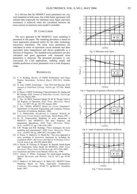
It is obvious that the MOSFET noise parameters are very<br />
well simulated in both cases, but a little better agreement with<br />
referent data (especially for minimum noise figure and noise<br />
resistance) is achieved when the correlation between the<br />
noise sources in transistor noise model is included.<br />
IV CONCLUSION<br />
The wave approach to RF MOSFETs’ noise modeling is<br />
presented in this paper. The modeling procedure is based on<br />
some approaches proposed earlier for the other technology<br />
microwave transistors. The noise wave parameters are<br />
calculated in terms of equivalent circuit elements and three<br />
equivalent noise temperatures and shown graphically as a<br />
function of frequency. The standard noise parameters are also<br />
calculated and good agreement with measured noise<br />
parameters is observed. The presented procedure is very<br />
convenient for CAD applications, enabling simple and<br />
reliable prediction of noise parameters over a wide frequency<br />
range.<br />
REFERENCES<br />
[1] T. E. Kolding, Review of CMOS Performance and Future<br />
Process Innovations, Technical Report R98-1014, October<br />
1988.<br />
[2] H. Iwai, CMOS Technology – Year 2010 and Beyond, IEEE<br />
<strong>Journal</strong> of Solid-State Circuits, Vol.34, pp. 357-366, March<br />
1999.<br />
[3] B. Razavi, CMOS Technology Characterization for Analog and<br />
RF Design, IEEE <strong>Journal</strong> of Solid-State Circuits, Vol.34, pp.<br />
268-276, March 1999.<br />
[4] C. Enz, An MOS Transistor Model for RF IC Design Valid in<br />
All Regions of Operation, IEEE Trans. Microwave Theory<br />
Tech., vol. MTT-50, pp. 342-359, January 2002.<br />
[5] C. Hu, “BSIM4 MOSFET Model for Circuit Simulation”,<br />
Department of Electrical Engineering and Computer Science,<br />
University of California, Berkeley, 2000.<br />
[6] J. A. Dobrowolski, Introduction to Computer Methods for<br />
Microwave Circuit Analysis and Design, Artech House, 1991.<br />
[7] M. W. Pospieszalski, Modeling of noise parameters of<br />
MESFET's and MODFET's and their frequency and<br />
temperature dependence, IEEE Trans. Microwave Theory<br />
Tech., vol.MTT-37, pp. 1340-1350, 1989.<br />
[8] S.W. Wedge and D.B. Rutledge, "Wave techniques for noise<br />
modeling and measurement", IEEE Trans. Microwave Theory<br />
Tech., vol.MTT-40, pp. 2004-2012, November 1992.<br />
[9] O. Pronić, V. Marković, N. Maleš-Ilić: "The wave approach to<br />
noise modeling of microwave transistors by including the<br />
correlation effect", Microwave and Optical Technology Letters,<br />
Vol.28, Issue 6, pp. 426-430, March 2001.<br />
[10] A. Pascht, M. Grözing, D. Wiegner, M. Berroth, Small-Signal<br />
and Temperature Noise Model for MOSFETs, IEEE Trans.<br />
Microwave Theory Tech. Vol.50, No.8, pp. 1927-1934, 2002.<br />
[11] Touchstone and Libra Users Manual, EEsof, Inc., 1990.<br />
[12] C. Giusto, C. White, Techniques for small-signal modeling,<br />
Applied Microwave and Wireless, Vol.12, No.5, pp. 42-46,<br />
2000.<br />
[13] V. Markovi}, B. Milovanovi}, N. Male{-Ili}, MESFET Noise<br />
Modeling Based on Three Equivalent Temperatures,<br />
Conference Proceedings EUMC’97, pp.966-971, Jerusalem,<br />
Israel, 1997.<br />
ELECTRONICS, VOL. 8, NO.1, MAY 2004. 25<br />
F min [dB]<br />
Mag (Γ opt )<br />
Ang (Γ opt ) [ o ]<br />
r n<br />
5.5<br />
5.0<br />
4.5<br />
4.0<br />
3.5<br />
3.0<br />
2.5<br />
2.0<br />
1.5<br />
1.0<br />
MOD1<br />
REF<br />
MOD2<br />
0.5<br />
2 3 4 5 6 7 8 9 10<br />
1.0<br />
0.9<br />
0.8<br />
0.7<br />
0.6<br />
f [GHz]<br />
Fig. 4. Minimum noise figure<br />
MOD1<br />
REF<br />
MOD2<br />
0.5<br />
2 3 4 5 6 7 8 9 10<br />
f [GHz]<br />
Fig. 5. Magnitude of optimum reflection coefficient<br />
60<br />
50<br />
40<br />
30<br />
20<br />
10<br />
MOD1<br />
REF<br />
MOD2<br />
0<br />
2 3 4 5 6 7 8 9 10<br />
f [GHz]<br />
Fig. 6. Angle of optimum reflection coefficient<br />
8<br />
7<br />
6<br />
5<br />
4<br />
3<br />
MOD1<br />
REF<br />
MOD2<br />
2<br />
2 3 4 5 6 7 8 9 10<br />
f [GHz]<br />
Fig. 7. Noise resistance