

elektronika electronics - Electronics Journal - Elektrotehnicki fakultet
elektronika electronics - Electronics Journal - Elektrotehnicki fakultet
elektronika electronics - Electronics Journal - Elektrotehnicki fakultet

Create successful ePaper yourself
Turn your PDF publications into a flip-book with our unique Google optimized e-Paper software.
42<br />
III. POSSIBILITIES OF TELEVISION SCANNING<br />
OPTICAL STEREOMICROSCOPY<br />
Television scanning optical stereomicroscopy, preserving<br />
main idea of scanning with probe, allows to use light probe<br />
which is free of destructive influence onto erythrocytes.<br />
As a base for such instrumentation creation, the television<br />
scanning optical microscope can be successfully used [1], as<br />
its maximum working magnification is 10000x at usage of a<br />
lens 40x and spatial resolution the tenth parts of micrometer,<br />
allows to find out a relief of erythrocytes surface.<br />
For analysis of erythrocytes surface architectonics it is<br />
necessary, that the scanning optical microscope creates a 3-D<br />
image of an object. The optical scheme of such<br />
stereomicroscope is shown in Fig. 2.<br />
1<br />
2<br />
4а<br />
6<br />
Fig. 2. The optical scheme of scanning stereomicroscope<br />
The scanner 1 on projection cathode-ray tube of high<br />
resolution with polychrome luminescence of a screen forms a<br />
micro raster, the luminous flux from which one by a lens 2 is<br />
transformed to a parallel pencil of rays. The interference light<br />
filter [4] 3a reflects one of spectral components on a metallic<br />
mirror 4a, which one routes a parallel pencil beam of light to<br />
a microscope lens 5a, in a focus of which one there is an<br />
investigated object 6 on a substrate 7. Diffused by the object<br />
light, collected by a lens 5b, having reflected from a metallic<br />
mirror 4b easily permeates the interference filter 3b on a<br />
photo multiplier 8b, the signal from which one goes in<br />
computer, adapted to stereo images processing and display.<br />
The light pencil of beam with other spectral component,<br />
passing through the interference filter 3a, is reflected from<br />
the filter 3b and mirror 4b, falling in the lens 5b, is dispersed<br />
by the object 6, collected by a lens 5a, reflected from a mirror<br />
4a and through the interference filter 3a falls on a photo<br />
multiplier 8a, the signal from which one also goes to the<br />
computer. Thus, the interference light filters, having split a<br />
light pencil of beam on two spectral components, lights the<br />
object from two sides, have ensured the information on the<br />
object, sufficient for construction 3-D image on the screen of<br />
computer monitor. The computer image processing with<br />
usage of a software used in a photogrammetry, allows to<br />
compound the topographic map of investigated object relief.<br />
8а<br />
3а<br />
ELECTRONICS, VOL. 8, NO.1, MAY 2004.<br />
5а 5в<br />
8в<br />
4в<br />
7<br />
3в<br />
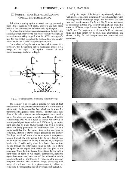
In Fig. 3 example of the images, experimentally obtained<br />
with microscope action simulation by one-channel television<br />
scanning optical microscope usage, are presented. 21x lens<br />
was used in microscope. Fig.3a and Fig 3b show test object<br />
as orthogonal metallic grid, covered with particles of another<br />
metal at different magnification. Dimensions of grid cell is<br />
30×30 µm. The erythrocytes of human’s blood (standard<br />
fixed and dyed smear for morphological examination) are<br />
shown in Fig. 3c. All images were not processed with<br />
computer.<br />
a)<br />
b)