

elektronika electronics - Electronics Journal - Elektrotehnicki fakultet
elektronika electronics - Electronics Journal - Elektrotehnicki fakultet
elektronika electronics - Electronics Journal - Elektrotehnicki fakultet

Create successful ePaper yourself
Turn your PDF publications into a flip-book with our unique Google optimized e-Paper software.
36<br />
Input<br />
ports<br />
Input<br />
ports<br />
Input<br />
ports<br />
MOD[S21]<br />
MOD[S21]<br />
1<br />
0.9<br />
0.8<br />
0.7<br />
0.6<br />
0.5<br />
0.4<br />
0.3<br />
0.2<br />
0.1<br />
0<br />
L1 L2 L6 L5 L4 L3 L2 L1<br />
50 Ω<br />
ELECTRONICS, VOL. 8, NO.1, MAY 2004.<br />
50 Ω<br />
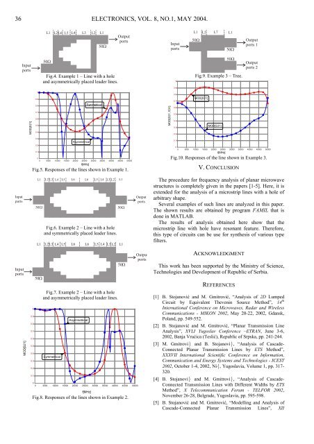
Fig.4. Example 1 – Line with a hole<br />
and asymmetrically placed leader lines.<br />
Asymmetrical<br />
Symmetrical<br />
Output<br />
ports<br />
0 5000 10000 15000 20000 25000 30000 35000 40000 45000 50000<br />
f[MHz]<br />
Fig.5. Responses of the lines shown in Example 1.<br />
1<br />
0.9<br />
0.8<br />
0.7<br />
0.6<br />
0.5<br />
0.4<br />
0.3<br />
0.2<br />
0.1<br />
L1 L2 L3 L4 L5 L6 L6 L5 L4 L3 L2 L1<br />
50 Ω 50 Ω<br />
50 Ω<br />
Fig.6. Example 2 – Line with a hole<br />
and symmetrically placed leader lines.<br />
L1 L2 L3 L4 L5 L6 L6 L5 L4 L3 L2 L1<br />
Fig.7. Example 2 – Line with a hole<br />
and asymmetrically placed leader lines.<br />
Symmetrical<br />
Asymmetrical<br />
50 Ω<br />
0<br />
0 5000 10000 15000 20000 25000 30000 35000 40000 45000 50000<br />
f[MHz]<br />
Fig.8. Responses of the lines shown in Example 2.<br />
Output<br />
ports<br />
Output<br />
ports<br />
MOD[S21, S31]<br />
Input<br />
ports<br />
1<br />
0.9<br />
0.8<br />
0.7<br />
0.6<br />
0.5<br />
0.4<br />
0.3<br />
0.2<br />
0.1<br />
0<br />
L1<br />
50Ω<br />
L2 L7<br />
L1<br />
50 Ω<br />
50 Ω<br />
Fig.9. Example 3 – Tree.<br />
MOD[S21]<br />
MOD[S31]<br />
Output<br />
ports 1<br />
Output<br />
ports 2<br />
0 5000 10000 15000 20000 25000 30000 35000 40000 45000 50000<br />
f[MHz]<br />
Fig.10. Responses of the line shown in Example 3.<br />
V. CONCLUSION<br />
The procedure for frequency analysis of planar microwave<br />
structures is completely given in the papers [1-5]. Here, it is<br />
extended for the analysis of a microstrip lines with a hole of<br />
arbitrary shape.<br />
Several examples of such lines are analyzed in this paper.<br />
The shown results are obtained by program FAMIL that is<br />
done in MATLAB.<br />
The results of analysis obtained here show that the<br />
microstrip line with hole have resonant feature. Therefore,<br />
this type of circuits can be use for synthesis of various type<br />
filters.<br />
ACKNOWLEDGMENT<br />
This work has been supported by the Ministry of Science,<br />
Technologies and Development of Republic of Serbia.<br />
REFERENCES<br />
[1] B. Stojanović and M. Gmitrović, “Analysis of 2D Lumped<br />
Circuit by Equivalent Thevenin Source Method”, 14 th<br />
International Conference on Microwaves, Radar and Wireless<br />
Communications - MIKON 2002, May 20-22, 2002, Gdansk,<br />
Poland, pp. 549-552.<br />
[2] B. Stojanović and M. Gmitrović, “Planar Transmission Line<br />
Analysis”, XVLI Yugoslav Conference –ETRAN, June 3-6,<br />
2002, Banja Vrućica (Teslić), Republic of Srpska, pp. 241-244.<br />
[3] M. Gmitrovi} and B. Stojanovi}, “Analysis of Cascade-<br />
Connected Planar Transmission Lines by ETS Method”,<br />
XXXVII International Scientific Conference on Information,<br />
Communication and Energy Systems and Technologies - ICEST<br />
2002, October 1-4, 2002, Ni{, Yugoslavia, Volume 1, pp. 317-<br />
320.<br />
[4] B. Stojanovi} and M. Gmitrovi}, “Analysis of Cascade-<br />
Connected Transmission Lines with Different Widths by ETS<br />
Method”, X Telecommunication Forum - TELFOR 2002,<br />
November 26-28, Belgrade, Yugoslavia, pp. 595-598.<br />
[5] B. Stojanović and M. Gmitrović, “Modelling and Analysis of<br />
Cascade-Connected Planar Transmission Lines”, XII