

elektronika electronics - Electronics Journal - Elektrotehnicki fakultet
elektronika electronics - Electronics Journal - Elektrotehnicki fakultet
elektronika electronics - Electronics Journal - Elektrotehnicki fakultet

You also want an ePaper? Increase the reach of your titles
YUMPU automatically turns print PDFs into web optimized ePapers that Google loves.
38<br />
content. The basic organisation of the courseware consist<br />
from four parts:<br />
Theoretical part - this is an interactive multimedia<br />
document about the theory of Applied Photonics.<br />
Practical part - this is an interactive multimedia based<br />
simulation and measurement supporting multimedia<br />
programme package able to solve CAD and CAE problems in<br />
the area of Applied Photonics.<br />
Part references - this is a multimedia document about<br />
published documents related to Applied Photonics.<br />
Part tests – the tests embedded to the courseware are<br />
entitled to evaluated the knowledge, routines and working<br />
shills obtained by students through the learning process.<br />
Measurement practising in Applied Photonics for a large<br />
number of students is an economic problem. One approach to<br />
solve this problem is to create web-based laboratory<br />
equipments which are available to students through using<br />
standard Internet Protocol procedures on WWW. This<br />
approach was choosed in the course for practising<br />
measurements in the chapter Fiber Optic Sensors, particularly<br />
in application of fiber optics refractometer.<br />
Supervisor<br />
Browsing<br />
Student<br />
Communication<br />
E-mail<br />
Talk<br />
Audio<br />
White Board<br />
Audio-Video<br />
Teacher<br />
ELECTRONICS, VOL. 8, NO.1, MAY 2004.<br />
References<br />
Theory<br />
Practical Part – simulation<br />
– web-based<br />
laboratories<br />
Tests<br />
Fig. 1. Co-operative modern teleeducation<br />
III. FEEDBACK IN THE PHOTONICS<br />
COURSEWARE<br />
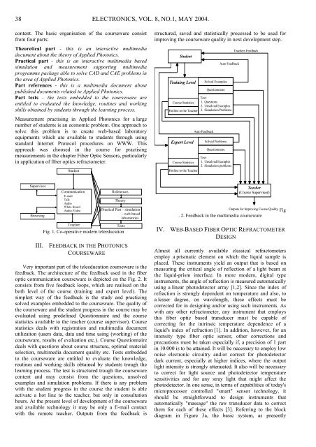
Very important part of the teleeducation courseware is the<br />
feedback. The architecture of the feedback used in the fiber<br />
optic communication courseware is depicted on the Fig. 2. It<br />
consists from five feedback loops, which are realised on the<br />
both level of the course (training and expert level). The<br />
simplest way of the feedback is the study and practicing<br />
solved examples embedded to the courseware. The quality of<br />
the courseware and the student progress in the course may be<br />
evaluated using predefined Questionnaire and the course<br />
statistics available to the teacher (course supervisor). Course<br />
statistics deals with registration and multimedia document<br />
utilization (users data, data and time using (working) of the<br />
courseware, results of evaluation etc.). Course Questionnaire<br />
deals with questions about course structure, optimal material<br />
selection, multimedia document quality etc. Tests embedded<br />
to the courseware are entitled to evaluate the knowledge,<br />
routines and working skills obtained by students trough the<br />
learning process. The test is structured trough the courseware<br />
content and may consist from the questions, unsolved<br />
examples and simulation problems. If there is any problem<br />
with the student progress in the course the student is able<br />
activate a hot line to the teacher, but only in consultation<br />
hours. At the present level of development of the courseware<br />
and available technology it may be only a E-mail contact<br />
with the remote teacher. Outputs from the feedback is<br />
structured, saved and statistically processed to be used for<br />
improving the courseware quality in next development step.<br />
Student<br />
Training Level<br />
Course Statistics<br />
Hotline to the Teacher<br />
Expert Level<br />
Course Statistics<br />
Hotline to the Teacher<br />
Solved Examples<br />
Questionnaire<br />
Test:<br />
1. Questions<br />
2. Unsolved Examples<br />
3. Simulation Problems<br />
Auto Feedback<br />
Solved Problems<br />
Questionnaire<br />
Auto Feedback<br />
Test:<br />
1. Unsolved Examples<br />
2. Simulation problems<br />
Teachers Feedback<br />
Teacher<br />
(Course Supervisor)<br />
Outputs for Improving Course Quality<br />
. 2. Feedback in the multimedia courseware<br />
IV. WEB-BASED FIBER OPTIC REFRACTOMETER<br />
DESIGN<br />
Almost all currently available classical refractometers<br />
employ a prismatic element on which the liquid sample is<br />
placed. These instruments yield an output that is based on<br />
measuring the critical angle of reflection of a light beam at<br />
the liquid-prism interface. In more modern, digital type<br />
instruments, the angle of reflection is measured automatically<br />
using a linear photodetector array [1,2]. Since the index of<br />
refraction is strongly dependent on temperature and also, to<br />
a lesser degree, on wavelength, these effects must be<br />
corrected for in designing and/or using such instruments. As<br />
with any other refractometer, any instrument that employs<br />
this fiber optic based transducer must be capable of<br />
correcting for the intrinsic temperature dependence of a<br />
liquid's index of refraction [1]. In addition, however, for an<br />
intensity type fiber optic sensor, other corrections and<br />
precautions must be taken especially if, a precision of 1 part<br />
in 10.000 is to be attained. It will be necessary to employ low<br />
noise electronic circuitry and/or correct for photodetector<br />
dark current, especially at higher indices, where the output<br />
light intensity is strongly attenuated. It also will be necessary<br />
to correct for light source and photodetector temperature<br />
sensitivities and for any stray light that might affect the<br />
photodetector. In one sense, in terms of capabilities of today's<br />
microprocessor controlled "smart" sensor technology, it<br />
should be straightforward to design instruments that<br />
automatically "massage" the raw transducer data to correct<br />
them for each of these effects [3]. Referring to the block<br />
diagram in Figure 3a, the basic system, as presently<br />
Fig