- Page 17 and 18: Abstract The construction of the LH
- Page 19 and 20: Following a decade of development a
- Page 21 and 22: VII. PERFORMANCE AND UPGRADE POTENT
- Page 23 and 24: efore, both after scaling. The resu
- Page 25: Abstract Most modern HEP experiment
- Page 29 and 30: mechanical rigidity and at the same
- Page 31 and 32: Abstract Some principal design feat
- Page 33 and 34: Energy → Light Light → Current
- Page 35 and 36: Accordion Electrodes SB MB Mother B
- Page 37 and 38: ADC Counts [RMS] 25 20 15 10 Calibr
- Page 39 and 40: I. EVOLUTION AND REVOLUTION FPGA pr
- Page 41 and 42: This flexibility is essential when
- Page 43 and 44: B. Designing for Signal Integrity S
- Page 45 and 46: D. Coping with Clock Reflections In
- Page 47 and 48: III. ANTIFUSE FPGA TECHNOLOGY FPGA
- Page 49 and 50: Figure 4 Schematic drawing of non-T
- Page 51 and 52: 1) Non-TMR design FF errors were ob
- Page 53 and 54: CrossSection [/bit/cm2] 1.00E-08 1.
- Page 55 and 56: Table 1: Characterization of the re
- Page 57 and 58: The search direction is opposite to
- Page 59 and 60: Design of ladder EndCap electronics
- Page 61 and 62: will maintain the token passing for
- Page 63 and 64: Analogue switches Figure 14 Analogu
- Page 65 and 66: Test Input Analog In Itp Testpulse
- Page 67 and 68: data header DataValid AnalogOut[0]
- Page 69 and 70: �Ò��Ò �� Ê����
- Page 71 and 72: Ì��Ð� � ��×��Ò
- Page 73 and 74: PRELIMINARY ���ÙÖ� ��
- Page 75 and 76: the simulations are: luminosity of
- Page 77 and 78:
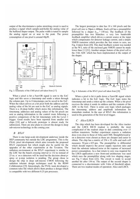
IV. PIXEL MODULE EXPERIMENTAL RESUL
- Page 79 and 80:
Radiation tolerance studies of BTeV
- Page 81 and 82:
Figure 1: Measured amplifier noise
- Page 83 and 84:
The ALICE Pixel Detector Readout Ch
- Page 85 and 86:
Control JTAG Multiplicity Pixel JTA
- Page 87 and 88:
irradiated chips can be changed by
- Page 89 and 90:
I. Preamplifier The preamplifier is
- Page 91 and 92:
the error amplifier. As a result, a
- Page 93 and 94:
Abstract The front−end system of
- Page 95 and 96:
III. Test results of the front−en
- Page 97 and 98:
Irradiation and SPS Beam Tests of t
- Page 99 and 100:
A. Measurements with Ions In order
- Page 101 and 102:
stepping motor. The results are sho
- Page 103 and 104:
uffer of the analogue multiplexer i
- Page 105 and 106:
The noise performance of the SCTA12
- Page 107 and 108:
The ALICE on-detector pixel PILOT s
- Page 109 and 110:
C. Data converter The serial-parall
- Page 111 and 112:
input logic block a logic block b l
- Page 113 and 114:
A Study of Thermal Cycling and Radi
- Page 115 and 116:
a result of accelerated oxidation w
- Page 117 and 118:
40MHz clock frequency and correspon
- Page 119 and 120:
Figure 5: S-curves and noise occupa
- Page 121 and 122:
Design and Test of a DMILL Module C
- Page 123 and 124:
the correct inputs for the MCC. Dat
- Page 125 and 126:
esults that predicted 78 MHz. One h
- Page 127 and 128:
There is no common behaviour for th
- Page 129 and 130:
the equivalent resistance is almost
- Page 131 and 132:
Low Dose Rate Effects And Ionizatio
- Page 133 and 134:
Figure 2: Relative beta change (∆
- Page 135 and 136:
ABCD chip will remain under specifi
- Page 137 and 138:
Since the TSM system is the bottlen
- Page 139 and 140:
architecture requires a comparable
- Page 141 and 142:
Neutron Radiation Tolerance Tests o
- Page 143 and 144:
c) voltage ON/OFF alternating in ra
- Page 145 and 146:
B. Optical measurements Plano-conve
- Page 147 and 148:
(RoI). It selects the higher trigge
- Page 149 and 150:
during communication with jtag tap.
- Page 151 and 152:
A Radiation Tolerant Gigabit Serial
- Page 153 and 154:
A. Evaluation Tests All the ASIC fu
- Page 155 and 156:
fifth workshop on electronics for L
- Page 157 and 158:
considered as an electronic friendl
- Page 159 and 160:
stored in one bunch crossing. Readi
- Page 161 and 162:
A Radiation Tolerant Laser Driver A
- Page 163 and 164:
A. Static performance Figure 4 show
- Page 165 and 166:
This is attributed to the NMOS type
- Page 167 and 168:
programme is that we must validate
- Page 169 and 170:
B. Lab simulation of the radiation
- Page 171 and 172:
Design and Performance of a Circuit
- Page 173 and 174:
Figure 4: Set-up for electrical tes
- Page 175 and 176:
Status Report of the ATLAS SCT Opti
- Page 177 and 178:
Figure 5 LI curves for VCSELs on a
- Page 179 and 180:
Figure 13 Measured noise occupancy
- Page 181 and 182:
of the PCB: 23 × 30 mm. The PCB th
- Page 183 and 184:
ange within noise spec. It is clear
- Page 185 and 186:
An Optical Link Interface for the T
- Page 187 and 188:
Not using integrated components mea
- Page 189 and 190:
Fig. 2 Open view of the AMT-2chip.
- Page 191 and 192:
Jitter[ps] 2.5 300 250 200 150 100
- Page 193 and 194:
Anode Front-End Electronics for the
- Page 195 and 196:
Input Figure 2: Schematic diagram o
- Page 197 and 198:
esulting curve of “propagation ti
- Page 199 and 200:
measured during each exposure. The
- Page 201 and 202:
IV. CONCLUSIONS The radiation tests
- Page 203 and 204:
A. Wilkinson ADC The Wilkinson dual
- Page 205 and 206:
D. Noise performance and non-system
- Page 207 and 208:
"The MAD", a Full Custom ASIC for t
- Page 209 and 210:
(slope of 45 e/pF) and a value belo
- Page 211 and 212:
COMPASS, a HEP experiment under con
- Page 213 and 214:
From CADENCE simulation the bandwid
- Page 215 and 216:
Figure 11: Shaper output for a 1/t
- Page 217 and 218:
supports also add-on bus mastering
- Page 219 and 220:
Each i-th FEE card has to produce P
- Page 221 and 222:
The results are shown in figure 7.
- Page 223 and 224:
TIM ( TTC Interface Module ) for AT
- Page 225 and 226:
FRONT PANEL 36 x L� EDS NIMINPUTS
- Page 227 and 228:
testing the FE and off-detector ele
- Page 229 and 230:
Channel B supports several function
- Page 231 and 232:
The ECS interface is a Credit Card
- Page 233 and 234:
Implementation Issues of the LHCb R
- Page 235 and 236:
III. ECS INTERFACE The Experiment C
- Page 237 and 238:
VII. PLD MODULES For the first prot
- Page 239 and 240:
Abstract CMS REGIONAL CALORIMETER T
- Page 241 and 242:
The jets and τs are characterized
- Page 243 and 244:
Figure 6. Jet trigger rates for sin
- Page 245 and 246:
A. Extrapolation A single Extrapola
- Page 247 and 248:
down to 5 clocks (125 ns) from 15 c
- Page 249 and 250:
The Sector Logic demonstrator of th
- Page 251 and 252:
In the same way, for each muon pass
- Page 253 and 254:
Figure 8: Layout of the MFCC with t
- Page 255 and 256:
On Detector In Trigger Cavern LAr (
- Page 257 and 258:
The ATLAS level-1 calorimeter trigg
- Page 259 and 260:
The Final Multi-Chip Module of the
- Page 261 and 262:
Analog In ¯ one four-channel PPrAS
- Page 263 and 264:
for the test. The signals are condi
- Page 265 and 266:
Cluster Processor Jet/Energy Jet En
- Page 267 and 268:
an internal DSS memory which was pr
- Page 269 and 270:
Prototype Slice of the Level-1 Muon
- Page 271 and 272:
Four low-pT CMAs, covering a total
- Page 273 and 274:
Figure 9: ATLAS Simulated Total Ion
- Page 275 and 276:
��� ��� ��� �
- Page 277 and 278:
WULJJHU HIIL�LHQ�\ $U $U 2 2 3
- Page 279 and 280:
Design and Test of the Track-Sorter
- Page 281 and 282:
eyond the LHC bunch crossing freque
- Page 283 and 284:
Use of Network Processors in the LH
- Page 285 and 286:
shortly discussed here. For details
- Page 287 and 288:
The network processor is accessed r
- Page 289 and 290:
Figure 2 : residuals of a linear fi
- Page 291 and 292:
3. FRONT-END BOARDS [8] The Front-e
- Page 293 and 294:
4. PRODUCTION STRATEGY Except the S
- Page 295 and 296:
The Delta pre-amplifier provides ch
- Page 297 and 298:
Output (Volts) 0.32 0.315 0.31 0.30
- Page 300 and 301:
Ì�� Ñ�Ü�� �Ò�ÐÓ
- Page 302 and 303:
����Ò×Ø ÐÓ � ÖÓ×
- Page 304 and 305:
Ì�� �ÙÒ Ø�ÓÒÒ�Ð
- Page 306 and 307:
The production and the test routine
- Page 308 and 309:
documented on the web. Baltazar has
- Page 310 and 311:
II. LOW VOLTAGE CONTROL OF HEC A. S
- Page 312 and 313:
1) Original design We intended to u
- Page 314 and 315:
On the developments of the Read Out
- Page 316 and 317:
This module has been developed and
- Page 318 and 319:
Abstract After reviewing the archit
- Page 320 and 321:
portation architecture must allow a
- Page 322 and 323:
The Embedded Local Monitor Board (E
- Page 324 and 325:
sender automatically re-attempts tr
- Page 326 and 327:
2) The result of the functional SEE
- Page 328 and 329:
Design of a Data Concentrator Card
- Page 330 and 331:
Figure 4: DCC modeling overview The
- Page 332 and 333:
selection process. PVSS-II also pro
- Page 334 and 335:
Figure 5: Bus activity after a SYNC
- Page 336 and 337:
Table 1: DCU Specifications # of ch
- Page 338:
Figure 9: ADC DNL in the LIR mode (
- Page 341 and 342:
II. A SYSTEMATICAL APPROACH TO DCS
- Page 343 and 344:
corresponding FE electronics segmen
- Page 345 and 346:
Abstract THE CMS HCAL DATA CONCENTR
- Page 347 and 348:
HTR L1A 40MHz Derand. Buffer Derand
- Page 349 and 350:
EMI Filter Design and Stability Ass
- Page 351 and 352:
dBuV 1 0 2 1 0 1 1 0 4 1 0 5 M I L
- Page 353:
The methodology followed in designi
- Page 356 and 357:
- > % o . 0 . / 2 9 . . . . - - / 2
- Page 358 and 359:
" " 2 0 ? 1 . 8 2 . - / 2 0 > . / 2
- Page 360 and 361:
Power Supply and Power Distribution
- Page 362 and 363:
for HF transformers and DC supply f
- Page 364:
2. J.Bohm, SCT Week Prague 25 − 2
- Page 367 and 368:
on fibre composite plates (150-330
- Page 369 and 370:
ures 3 and 4 (only one half of the
- Page 371 and 372:
Sorting Devices for the CSC Muon Tr
- Page 373 and 374:
In addition to that, the MS perform
- Page 375 and 376:
Optical Link Evaluation for the CSC
- Page 377 and 378:
III. PROTOTYPING RESULTS Two evalua
- Page 379 and 380:
DISTRIBUTED MODLAR RT-SYSTEMS FOR D
- Page 381 and 382:
equired also for describing of mode
- Page 383 and 384:
point links, which eliminated the b
- Page 385 and 386:
Technology Independent System archi
- Page 387 and 388:
¡£¢¥¤§¦©¨�¢���¦
- Page 389 and 390:
�����������
- Page 391 and 392:
�����¥������
- Page 393 and 394:
Figure 2: Schematic of Prototype Ev
- Page 395 and 396:
D. Irradiation Results on the Inter
- Page 397 and 398:
Printed Circuit Board Signal Integr
- Page 399 and 400:
Package Parasitic GND R_pkg L C_pkg
- Page 401 and 402:
Figure 8: ALICE Pixel System Detect
- Page 403 and 404:
are described in [8]. The temperatu
- Page 405 and 406:
The Behavior of P-I-N Diode under H
- Page 407 and 408:
Figure 5: Numerical (line) and expe
- Page 409 and 410:
Elements Silicon sensors Table 1: T
- Page 411 and 412:
Table 2: Dominant radionuclides con
- Page 413 and 414:
VII. REFERENCES [1] I.Dawson, Revie
- Page 415 and 416:
LHC_CLK DATA_L[15..0] DATA_VALID_L
- Page 417 and 418:
the ionization takes place, and the
- Page 419 and 420:
Figure 2: Sketch of kinematics of t
- Page 421 and 422:
Figure 1. The ROD -Busy tree struct
- Page 423 and 424:
for setting the base address of the
- Page 425 and 426:
Optically Based Charge Injection Sy
- Page 427 and 428:
Figure 6: Measured crosstalk. A sig
- Page 429 and 430:
them through the connectors. The ju
- Page 431 and 432:
trigger type parameter (8 bit), whi
- Page 433 and 434:
¯ ÅÙÐØ�ÔÐ� × �ØØ�
- Page 435 and 436:
×Ø�Ô �Ý ×Ø�Ô ÓÒ�
- Page 437 and 438:
• a 4-channel ASIC of a different
- Page 439 and 440:
structures. One should acknowledge,
- Page 441 and 442:
New building blocks for the ALICE S
- Page 443 and 444:
4 is more sensitive than the archit