

VHDL Made Easy! - Xilinx
VHDL Made Easy! - Xilinx
VHDL Made Easy! - Xilinx
- TAGS
- vhdl
- xilinx
- www.xilinx.com

Create successful ePaper yourself
Turn your PDF publications into a flip-book with our unique Google optimized e-Paper software.
42<br />
Advanced Carry-Logic Techniques<br />
All XC4000 series FPGAs provide<br />
dedicated carry generation logic within<br />
configurable logic blocks (CLBs), and<br />
dedicated routing to propagate carry<br />
signals between CLBs. Most basic carry-<br />
MULTIPLICATION<br />
Perhaps the simplest adaptation of the<br />
carry logic is to provide a multiplier function.<br />
In a multiplier, one of the input<br />
words, X, is ANDed separately with each<br />
bit of the other input word, Y, and the<br />
resulting words are summed with appropriate<br />
binary weighting. Consequently,<br />
there is a need for gated adders, such as<br />
shown in Figure 1(a).<br />
However, it is inefficient to implement<br />
this function as drawn. The carry logic<br />
connects directly to the input pins of the<br />
CLB, and there is no provision to dynamically<br />
gate the carry logic inputs. Instead of<br />
using an additional CLB for the gating, the<br />
function can be modified as shown in<br />
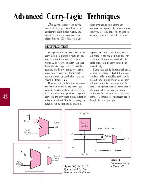
Figures 1(a), top left, &<br />
1(b), bottom left, Two<br />
Versions of a Gated Adder<br />
logic applications, like adders and<br />
counters, are supported by library macros.<br />
However, the carry logic can be used in<br />
other ways for more specialized circuits.<br />
Figure 1(b). This circuit is functionally<br />
equivalent to the one of Figure 1(a), provided<br />
that all inputs are gated with the<br />
same signal, and the carry signal is not<br />
used directly.<br />
Figure 1(b) can be implemented easily,<br />
as shown in Figure 2. Each bit of a conventional<br />
adder is modified such that the<br />
unconditional sum is created as an internal<br />
node in the function generator. This<br />
sum is multiplexed with the partial sum to<br />
the adder, which is already available<br />
within the function generator. The gating<br />
signal, Y i , controls the multiplexer, and is<br />
brought in on a spare pin.<br />
Figure 2<br />
Implementation of<br />
a Gated Adder


