211-125A Table Assembly - Atlanta Attachment Co.
211-125A Table Assembly - Atlanta Attachment Co.
211-125A Table Assembly - Atlanta Attachment Co.

Create successful ePaper yourself
Turn your PDF publications into a flip-book with our unique Google optimized e-Paper software.
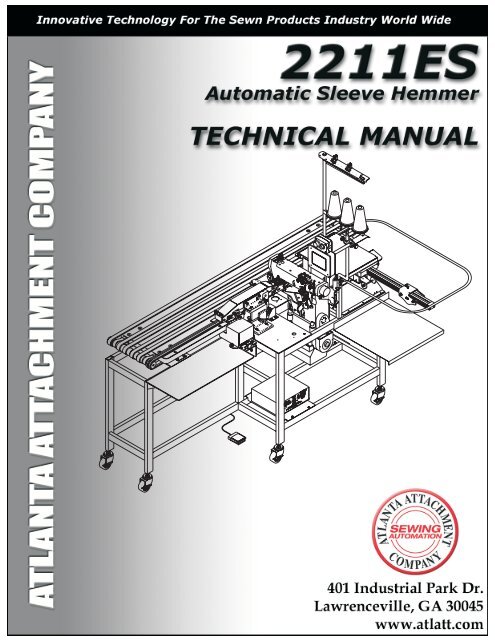
Manual No. ZZ<strong>211</strong>ES<br />
Automatic<br />
Two Needle Hemmer<br />
Installation Intructions,<br />
Parts Lists<br />
And Diagrams For<br />
2<strong>211</strong>ES<br />
Automatic<br />
Two Needle Hemmer<br />
W/ Serial Bus<br />
For<br />
Pegasus<br />
Rimoldi<br />
Singer<br />
Yamato<br />
Last Updated: 2-12-2003<br />
<strong>Co</strong>pyright© 1998-2003<br />
By<br />
<strong>Atlanta</strong> <strong>Attachment</strong><br />
<strong>Co</strong>mpany<br />
Incorporated<br />
All Rights Reserved<br />
This equipment is protected by one or more of the<br />
following patents:<br />
US patents:4,038,933; 4,280,421; 4,432,294; 4,466,367;<br />
4,644,883; 4,886,005; 5,134,947; 5,159,889; 5,203,270;<br />
5,307,750; 5,373,798; 5,437,238; 5,522,332; 5,524,563;<br />
5,562,060; 5,634,418; 5,647,293; 5,657,711; 5,743,202;<br />
5,865,135; 5,899,159; 5,915,319; 5,918,560; 5,924,376;<br />
5,979,345, 6,035,794<br />
Foreign patents - 2,084,055; 2,076,379;<br />
2,177,389; 2,210,569; 4-504,742; 8-511,916; 9-520,472;<br />
0,537,323; 92,905,522.6; 95,935,082.8; 96,936,922.2.<br />
Manual No. ZZ<strong>211</strong>ES<br />
Dobladillador<br />
Automatico De 2 Agujas<br />
Instrucciones de Instalación,<br />
Lista De Partes,<br />
y Diagramas Para<br />
2<strong>211</strong>ES<br />
Dobladillador<br />
Automático de Dos Agujas.<br />
<strong>Co</strong>n Bus Serie<br />
Para<br />
Pegasus<br />
Rimoldi<br />
Singer<br />
Yamato<br />
Last Updated: 2-12-2003<br />
Derechos De Autor© 1998-2003<br />
Por<br />
La <strong>Co</strong>mpañía<br />
<strong>Atlanta</strong> <strong>Attachment</strong><br />
Incorporada.<br />
Derechos Reservados<br />
Este equipo es fabricado bajo una o más de las<br />
patentes siguientes:<br />
En EE.UU; .4,038,933; 4,280,421; 4,432,294; 4,466,367;<br />
4,644,883; 4,886,005; 5,134,947; 5,159,889; 5,203,270;<br />
5,307,750; 5,373,798; 5,437,238; 5,522,332; 5,524,563;<br />
5,562,060; 5,634,418; 5,647,293; 5,657,711; 5,743,202;<br />
5,865,135; 5,899,159; 5,915,319; 5,918,560; 5,924,376;<br />
5,979,345, 6,035,794<br />
Patentes en el extranjero - 2,084,055; 2,076,379; 2,177,389;<br />
2,210,569; 4-504,742; 8-511,916; 9-520,472; 0,537,323;<br />
92,905,522.6; 95,935,082.8; 96,936,922.2.
(770)963-7369 FAX(770)963-7641 2<strong>211</strong>ES<br />
<strong>Table</strong> of <strong>Co</strong>ntents<br />
General Operating Instructions And Adjustments ------------------------------------1-6<br />
Instrucciones Generales de Operaciones y Ajustes -----------------------------------1-6<br />
Operating Instructions -------------------------------------------------------1-7<br />
Instrucciones de Operación ---------------------------------------------------1-7<br />
<strong>Co</strong>ntrol Box --------------------------------------------------------------1-8<br />
Instructions for <strong>211</strong>ES -------------------------------------------------------1-8<br />
Instrucciones para la <strong>211</strong>ES ---------------------------------------------------1-8<br />
<strong>211</strong>ES Main Screen: --------------------------------------------------------1-9<br />
Advanced Functions: --------------------------------------------------------1-9<br />
Primera Página de la Pantalla --------------------------------------------------1-9<br />
Funciones Técnicas ---------------------------------------------------------1-9<br />
Advanced Settings 1: --------------------------------------------------------1-10<br />
<strong>Co</strong>nfiguraciones 1: ---------------------------------------------------------1-10<br />
Advanced Settings 2: --------------------------------------------------------1-11<br />
Manual Input Test: ----------------------------------------------------------1-11<br />
Manual Output Test: ---------------------------------------------------------1-11<br />
<strong>Co</strong>nfiguración 2: ----------------------------------------------------------1-11<br />
Ayuda Prueba de Entradas ----------------------------------------------------1-11<br />
Ayuda Prueba de Salidas -----------------------------------------------------1-11<br />
Operator Screen: ----------------------------------------------------------1-12<br />
Possible Machine Errors: -----------------------------------------------------1-12<br />
Página Del Operador --------------------------------------------------------1-12<br />
Errores Posibles ----------------------------------------------------------1-12<br />
Thread Break Detectors ------------------------------------------------------1-15<br />
Detectores de Rotura del Hilo --------------------------------------------------1-15<br />
Thread Sensor Instructions ----------------------------------------------------1-15<br />
Ajustes a la Guía de la Recortadora de Borde --------------------------------------1-16<br />
Adjustments to the Material Edge Trimming Guide System -----------------------------1-16<br />
Adjustment to the Thread Chain Puller and Speed <strong>Co</strong>ntrol ------------------------------1-17<br />
Ajustes al Tiracadeneta y al <strong>Co</strong>ntrol de Velocidad. -----------------------------------1-17<br />
Troubleshooting ----------------------------------------------------------1-19<br />
Problemas y Soluciones ------------------------------------------------------1-19<br />
Sewing HeadMaintenance ----------------------------------------------------2-1<br />
Mantenimiento del Cabezal ---------------------------------------------------2-1<br />
Ajustes Para Pegasus W664 ---------------------------------------------------2-3<br />
Suggested Sewing Guidelines For Pegasus W664 -----------------------------------2-3<br />
Ajustes Sugeridos Para Rimoldi ------------------------------------------------2-11<br />
Suggested Sewing Guidelines For Rimoldi -----------------------------------------2-11<br />
Phase Sheet ----------------------------------------------------------2-15<br />
Suggested Guidelines And Instructions For Yamato VC2600 ----------------------------2-17<br />
Ajustes e Instrucciones Para Yamato VC2600 --------------------------------------2-17<br />
Preventative Maintenance Schedule ---------------------------------------------2-26<br />
Plan De Mantenimiento Preventivo ----------------------------------------------2-26<br />
Part List Directions ----------------------------------------------------------3-1<br />
<strong>Co</strong>nfiguration ----------------------------------------------------------3-2<br />
2<strong>211</strong>ESY6701 Auto Hemmer Yamato 5.6 mm Ga. W/ Panasonic Motor --------------------3-3<br />
2<strong>211</strong>ESY6702 Auto Hemmer Yamato 5.6mm Ga. W/ Panasonic Motor --------------------3-5<br />
<strong>211</strong>-G6606C Hemming Folder <strong>Assembly</strong> ------------------------------------------3-6<br />
311-060 Imitation Cuff Folder --------------------------------------------------3-7<br />
<strong>211</strong>-126C <strong>Table</strong> <strong>Assembly</strong> W/ Panasonic Motor -------------------------------------3-9<br />
<strong>211</strong>-121A Edge Trimmer <strong>Assembly</strong> ----------------------------------------------3-11<br />
<strong>211</strong>-128 Lower <strong>Co</strong>nveyor <strong>Assembly</strong> ---------------------------------------------3-13<br />
<strong>211</strong>-123 Belt Idler <strong>Assembly</strong>, Narrow ---------------------------------------------3-14<br />
<strong>211</strong>-<strong>125A</strong> <strong>Table</strong> <strong>Assembly</strong> ----------------------------------------------------3-15<br />
<strong>211</strong>-034 Transfer Drive <strong>Assembly</strong> ----------------------------------------------3-16<br />
<strong>211</strong>-G6602 Drive Train <strong>Assembly</strong> ----------------------------------------------3-17<br />
2<strong>211</strong>ES ATLANTA ATTACHMENT COMPANY 1-3<br />
401 Industrial Park Dr.-Lawrenceville, GA. 30045
2<strong>211</strong>ES (770)963-7369 FAX(770)963-7641<br />
Description Pg.<br />
<strong>211</strong>-124B Bottom Side <strong>Assembly</strong> -----------------------------------------------3-19<br />
<strong>211</strong>-209 Electronic <strong>Assembly</strong> --------------------------------------------------3-21<br />
0411-1057 Waste Venturi <strong>Assembly</strong> ---------------------------------------------3-22<br />
<strong>211</strong>-120 Mount, Edge Trimmer <strong>Assembly</strong> ------------------------------------------3-23<br />
<strong>211</strong>-151A Stacker, Pick & Stack ------------------------------------------------3-25<br />
016-014A Material Clamp <strong>Assembly</strong> ---------------------------------------------3-27<br />
<strong>211</strong>-134 Top <strong>Co</strong>nveyor -------------------------------------------------------3-29<br />
<strong>211</strong>-171 Top <strong>Co</strong>nveyor, Generic ------------------------------------------------3-31<br />
<strong>211</strong>-134B Top <strong>Co</strong>nveyor, 2 Belts, 3/4 Wide ----------------------------------------3-33<br />
311-002 Main Drive ---------------------------------------------------------3-34<br />
311-061 Keel <strong>Assembly</strong> ------------------------------------------------------3-35<br />
0411-1300 Waste <strong>Co</strong>ntainer <strong>Assembly</strong> -------------------------------------------3-37<br />
<strong>211</strong>-162 Indexing <strong>Table</strong> ------------------------------------------------------3-38<br />
311-006 Fold In Half Stacker<strong>Assembly</strong> -------------------------------------------3-39<br />
311-006B Fold In Half <strong>Assembly</strong> ------------------------------------------------3-41<br />
311-006A Fold In Half Stacker Sub-<strong>Assembly</strong> --------------------------------------3-43<br />
025-001 <strong>Co</strong>ntrol Box <strong>Assembly</strong> -------------------------------------------------3-45<br />
025-025 Indexing <strong>Table</strong> For Fold In Half Stacker ------------------------------------3-46<br />
025-027 <strong>Co</strong>ntrol Box <strong>Assembly</strong> -------------------------------------------------3-47<br />
Pneumatic and Wiring Diagrams ------------------------------------------------3-49<br />
<strong>211</strong>ES-PD1 Pneumatic Diagram ------------------------------------------------3-50<br />
025-025PD Pneumatic Diagram ------------------------------------------------3-51<br />
025-PD1 Pneumatic Diagram --------------------------------------------------3-52<br />
<strong>211</strong>ES-WD1 Wiring Diagram Panasonic Motor --------------------------------------3-53<br />
025-WD2 Wiring Diagram -----------------------------------------------------3-54<br />
025-WD3 Wiring Diagram -----------------------------------------------------3-55<br />
025-WD4 Wiring Diagram -----------------------------------------------------3-56<br />
025-025WD Wiring Diagram ---------------------------------------------------3-57<br />
Sewing Head Details- --------------------------------------------------------4-1<br />
<strong>211</strong>-127A Stitching Head <strong>Assembly</strong> for Yamato VC2700 -------------------------------4-3<br />
Gauge Parts, Yamato --------------------------------------------------------4-3<br />
<strong>211</strong>-122A Footlift Sub-<strong>Assembly</strong> ------------------------------------------------4-4<br />
311-3000C Chain Puller <strong>Assembly</strong> -----------------------------------------------4-5<br />
AP-22E-105 Drive Motor <strong>Assembly</strong> ----------------------------------------------4-6<br />
<strong>211</strong>-129 Chain Trimmer- ------------------------------------------------------4-7<br />
311-2017 Thread Trim <strong>Assembly</strong> ------------------------------------------------4-9<br />
3101760 Thread Handling Kit- --------------------------------------------------4-10<br />
311-2018 Adjustment Instructions -----------------------------------------------4-11<br />
1-4 ATLANTA ATTACHMENT COMPANY 2<strong>211</strong>ES<br />
401 Industrial Park Dr.-Lawrenceville, GA. 30045
Description<br />
The <strong>Atlanta</strong> <strong>Attachment</strong> <strong>Co</strong>mpany’s<br />
high speed automatic Two Needle cover<br />
stitch hemming workstation is a<br />
combination unit for sleeves, pockets and<br />
bodies complete with stacking capability<br />
for all.<br />
The 2<strong>211</strong>ES is a versatile unit for<br />
hemming sleeves, pockets and bodies. It<br />
is available with picker stacker, return<br />
conveyor and fold in half stacker.<br />
The modular design of AAC’s Two<br />
Needle Hemmer allows the flexibility of<br />
picking the combination of components to<br />
design a custom system best suited to<br />
the need.<br />
Description: An electronically controlled<br />
workstation consisting of a conveyorized<br />
downturn hemming apparatus with two<br />
needle bottom cover stitch sewing head,<br />
electronic motor, automatic edge trim and<br />
cut part.<br />
Operation: The operator places parts to<br />
an edge guide and initiates sewing. The<br />
unit will continue sewing as long as parts<br />
are placed on the conveyor within a<br />
specific distance. The sew cycle will stop<br />
if the operator fails to position the next<br />
part, thereby reducing thread waste.<br />
Average production on sleeves is 350 -<br />
400 dozen pair per 8 hour day.<br />
CAUTION<br />
There are cloth and thread trimming knives on<br />
this piece of equipment. These knives cut<br />
automatically. DO NOT put fingers or hands in or<br />
around these knives.<br />
All adjustments made to the Sewing machine head<br />
or knives should be made with power “OFF”.<br />
(770)963-7369 FAX(770)963-7641 2<strong>211</strong>ES<br />
Descripción<br />
La máquina dobladilladora de alta<br />
velocidad de Dos agujas e hilo de<br />
recubrir de la <strong>Co</strong>mpañía <strong>Atlanta</strong><br />
<strong>Attachment</strong> es una unidad combinación<br />
de mangas, bolsillos y cuerpos completos<br />
con capacidad de apilado para todos.<br />
La 2<strong>211</strong>ES es una unidad versátil para<br />
dobladillar mangas, bolsillos y cuerpos.<br />
Esta unidad está disponible con apilador<br />
automático, transportador de retorno y<br />
doblador apilador automático.<br />
El diseño modular de la Dobladilladora<br />
de Dos Agujas de la AAC permite la<br />
flexibilidad de escoger la combinación de<br />
componentes para diseñar un sistema<br />
que más se acomode a sus necesidades.<br />
Descripción: Es una estación de trabajo<br />
controlada electrónicamente que consiste<br />
de un aparato dobladillador con<br />
transportador, cabezal de máquina de<br />
coser de dos agujas e hilo de recubrir<br />
inferior,motor electrónico, cortador<br />
automático de borde.<br />
Operación: El operario coloca las partes<br />
a una guía e inicia la costura. La unidad<br />
continuará cosiendo mientras que partes<br />
sean colocadas en el transportador<br />
dentro de una distancia específica. El<br />
ciclo de costura parará si el operario falla<br />
en poner la siguiente parte, de ésta forma<br />
reduciendo el gasto de hilo. La<br />
producción promedio de mangas es de<br />
PRECAUCIÓN<br />
En este equipo hay cuchillas para cortar hilo y<br />
material. Estas cuchillas cortan automáticamente.<br />
NO ponga los dedos o las manos en o alrededor de<br />
estas cuchillas.<br />
Todos los ajustes hechos al cabezal de la máquina<br />
de coser o a las cuchillas deben hacerse con la<br />
electricidad a la máquina APAGADA.<br />
2<strong>211</strong>ES ATLANTA ATTACHMENT COMPANY 1-5<br />
401 Industrial Park Dr.-Lawrenceville, GA. 30045
2<strong>211</strong>ES (770)963-7369 FAX(770)963-7641<br />
General Operating<br />
Instructions<br />
And<br />
Adjustments for the<br />
2<strong>211</strong>ES<br />
Two Needle Hemmers<br />
Instrucciones Generales<br />
de Operaciones y<br />
Ajustes Para la<br />
Dobladilladora<br />
de Dos Agujas<br />
2<strong>211</strong>ES<br />
1-6 ATLANTA ATTACHMENT COMPANY 2<strong>211</strong>ES<br />
401 Industrial Park Dr.-Lawrenceville, GA. 30045
Operating Instructions<br />
2<strong>211</strong>ES<br />
Two-Needle Hemmer<br />
READ ALL THESE INSTRUCTIONS BEFORE OP-<br />
ERATING MACHINE!<br />
Wire the power cord to 208-230 VAC, 1 phase.<br />
<strong>Co</strong>nnect 1/4" air line to the air input connector with<br />
10CFM. Check regulators for proper PSI. The regulator<br />
should be set to 70 PSI.<br />
There is a control box mounted below the sewing head<br />
(see page 1-8). This box controls the stepping motor that<br />
drive the conveyors and the Chain Puller. The three<br />
thumbwheels on the top box are set to synchronize the<br />
two conveyors to the sewing machine. If you change the<br />
sewing stitch length, it will be necessary to adjust these<br />
numbers to re-synchronize the conveyors to the sewing<br />
machine. Decreasing the number makes the conveyors<br />
go slower. For example, if you changed the stitch length<br />
from 10 SPI to 11 SPI, you would need to decrease the<br />
number in the thumbwheels by 10% to match the 10%<br />
shorter stitch length. There is also a “Jog” button on the<br />
top box. Pressing this button will run the conveyors<br />
when the sewing machine is not running. On the back of<br />
the box, there is a fuse holder and an on/off switch.<br />
Leave the switch on, except to do maintenance on the<br />
stepper motors or conveyors.<br />
(770)963-7369 FAX(770)963-7641 2<strong>211</strong>ES<br />
Instrucciones de Operación<br />
Dobladillador de Dos Agujas<br />
2<strong>211</strong>ES<br />
¡LEA TODAS ESTAS INSTRUCCIONES<br />
ANTES DE OPERAR LA MAQUINA!<br />
<strong>Co</strong>necte a una corriente de 208-230 de voltaje de<br />
<strong>Co</strong>rriente Alterna, de 1 fase.<br />
<strong>Co</strong>necte la maguera de 1/4" al conector de entrada de<br />
aire con 10 Pies Cub. Por Min. Chequeé los<br />
reguladores por el PSI (Libras de presión por pulgada<br />
cuadrada) correcto. El regulador debe ser fijado a 70<br />
PSI.<br />
La caja de control está montada debajo del cabezal<br />
(vea página 1-8). Esta caja controla el motor que mueve<br />
los transportadores y el Tiracadeneta. Los tres<br />
selectores en la caja de arriba son para sincronizar los<br />
dos transportadores. Si cambia el largo de la puntada<br />
tiene que ajustar estos números para volver a<br />
sincronizar los transportadores a la máquina. Disminuir<br />
el número hace que los transportadores se muevan<br />
más lentamente. Por ejemplo, si cambia el largo de la<br />
puntada de 10 PPP (Puntadas por pulgada) a 11 PPP,<br />
debe disminuir el número en los selectores en 10% para<br />
igualar el 10% de puntada más corta. También hay un<br />
botón “PRUEBA MANUAL / AJUSTE” en la caja de<br />
arriba. Cuando hunde este botón los transportadores se<br />
mueven cuando la máquina no está funcionando. En la<br />
parte de atras de la caja de arriba, hay un fusible y un<br />
interruptor. Deje el interruptor en encendido (ON),<br />
excepto cuando va a hacer el mantenimiento al motor<br />
paso a paso o a los transportadores.<br />
2<strong>211</strong>ES ATLANTA ATTACHMENT COMPANY 1-7<br />
401 Industrial Park Dr.-Lawrenceville, GA. 30045
2<strong>211</strong>ES (770)963-7369 FAX(770)963-7641<br />
Instructions for <strong>211</strong>ES<br />
Note:The row of buttons across the bottom of the screen<br />
are called Standard buttons. They will appear or change<br />
based on the needs of the current screen.<br />
1. RESET: Always brings the machine back to its<br />
original power up state.<br />
2. HELP: Will take you to a help screen pertaining to<br />
the screen you are currently in.<br />
3. LANGUAGE: Allows you to change to a different<br />
language.<br />
4. EXIT: Leaves the current screen and takes you to<br />
an appropriate screen (usually back one level or to<br />
the previous screen you were on).<br />
5. START: Starts an event or function based on<br />
current screen information.<br />
6. CONTINUE: Used to restart an event or function<br />
that has been temporarily paused or suspended.<br />
7. HOME: Leaves the current screen and takes you to<br />
an appropriate screen (usually to the main<br />
operating screen.<br />
8. CLOCK: While on the Main Screen it allows you to<br />
set the time and date. On all other screens it is a<br />
display only.<br />
<strong>Co</strong>ntrol Box<br />
AP-28-800N<br />
<strong>Co</strong>nveyor Speed <strong>Co</strong>ntrol Box<br />
Instrucciones para la <strong>211</strong>ES<br />
Nota: Los botones a lo largo de la parte de abajo de la<br />
pantalla son los botones standard. Aparecen o cambian<br />
según las necesidades de la pantalla en uso.<br />
1. RECOMENZAR: Siempre lleva la máquina a la<br />
configuración original de encendido.<br />
2. AYUDA: Llega hasta una pantalla con ayuda<br />
pertinente .<br />
3. LENGUAJE: Le permite cambiar a un idioma<br />
diferente.<br />
4. SALIDA: Deja la página en donde está y lo lleva a<br />
la página apropiada ( generalmente un nivel o a la<br />
página anterior donde estaba)<br />
5. COMENZAR: <strong>Co</strong>mienza la función pertinente a la<br />
información en la pantalla.<br />
6. CONTINUE: <strong>Co</strong>ntinua la función suspendida<br />
temporalmente.<br />
7. PRIMERA PÁGINA: Deja la página en donde está y<br />
lo lleva a la página apropiada ( generalmente LA<br />
PRIMERA página)<br />
8. RELOJ: Mientras en la Primer Página le permite<br />
fijar el tiempo y la fecha. En las otras páginas solo<br />
lo muestra.<br />
1-8 ATLANTA ATTACHMENT COMPANY 2<strong>211</strong>ES<br />
401 Industrial Park Dr.-Lawrenceville, GA. 30045
<strong>211</strong>ES Main Screen:<br />
1. Leading Chop: This setting allows the user to<br />
control the amount of time from the sew eye<br />
seeing the leading edge of a sleeve till the<br />
leading edge chain chop occurs. The higher the<br />
number the shorter the length of chain.<br />
2. Piece <strong>Co</strong>unter: This is an adjustable piece<br />
counter that increments every time the stacker<br />
operates in automatic mode.<br />
3. Trailing Chop: This setting allows the user to<br />
control the amount of time from the sew eye<br />
seeing the trailing edge of a sleeve till the trailing<br />
edge chain chop occurs. The lower the number<br />
the shorter the length of chain.<br />
4. Manual Cut: Pressing this button manually<br />
activates the thread chop knife.<br />
5. <strong>Co</strong>nveyor Stop: This setting <strong>Co</strong>ntrols the length of<br />
time the conveyor runs after hemming is finished.<br />
It must be set high enough to allow the last<br />
sleeve loaded to be stacked. The higher the<br />
number the longer the conveyor will run. This<br />
setting also affects whether the machine runs<br />
continually or stops between sleeves. If the gap<br />
between sleeves is large enough the machine will<br />
stop and will have to be restarted by pressing the<br />
Start in Automatic Mode button or pressing the<br />
foot switch. <strong>Co</strong>nversely, if the gap is less the<br />
allotted the machine will run continually as long<br />
as sleeves are being loaded.<br />
6. <strong>Co</strong>nveyor Jog: This button allows the operator the<br />
manually run the conveyor if needed.<br />
7. Advanced Functions: This button takes you to the<br />
Advanced Functions screen<br />
8. Operator Screen: This button takes you to the<br />
Operator Screen (see pg. 1-12).<br />
9. Start in Automatic Mode: This button starts the<br />
machine in automatic mode allowing the machine<br />
to run continually as long as sleeves are being<br />
loaded.<br />
10. Switch to Manual Mode: This button takes you to<br />
a screen which allows the operator to manually<br />
run the sewing head in either sewing or chaining<br />
mode<br />
Advanced Functions:<br />
1. Advanced Settings: This button gives access to<br />
all available settings for the machine. Mechanic<br />
security level required.<br />
2. Manual Input Test: This button takes you to the<br />
Manual Input Test screen which allows you to test<br />
the input devices on the machine, such as:<br />
photoelectric eyes and switches. Mechanic<br />
security level required.<br />
(770)963-7369 FAX(770)963-7641 2<strong>211</strong>ES<br />
Primera Página de la Pantalla<br />
1. <strong>Co</strong>rte delantero: <strong>Co</strong>ntrola el tiempo desde que el<br />
sensor detecta el borde delantero de la manga<br />
hasta que la cadeneta delantera es cortada.<br />
Entre más grande el número más corta la<br />
cadeneta.<br />
2. <strong>Co</strong>ntador: <strong>Co</strong>ntador reajustable que aumenta<br />
cada vez que el apilador opera en modo<br />
automático.<br />
3. <strong>Co</strong>rte trasero: <strong>Co</strong>ntrola el tiempo desde que el<br />
sensor detecta el borde trasero hasta que la<br />
cadeneta trasera es cortada.<br />
Entre menor el número menor el tamaño de la<br />
cadeneta.<br />
4. <strong>Co</strong>rte Manual: Hundir este botón activa el<br />
cortacadeneta.<br />
5. Parada del Transportador: <strong>Co</strong>ntrola el tiempo que<br />
el transportador funciona después que la manga<br />
ha sido terminada. Debe ser lo suficientemente<br />
alto para permitir que la última manga cargada<br />
sea apilada. Entre más alto el número más<br />
tiempo funciona el transportador. Esta<br />
configuración hace que la máquina funcione<br />
continuamente o que pare entre mangas. Si la<br />
separación entre mangas es muy grande la<br />
máquina se para y para seguir tiene que<br />
presionar <strong>Co</strong>menzar en Automático o el<br />
interruptor del pie. Si la separación es poca,<br />
funcionará continuamente mientras se cargada.<br />
6. Prueba del Transportador: Permite al operador<br />
hacer funcionar el transportador si necesita.<br />
7. Funciones Técnicas: Este lo lleva a Funciones<br />
Técnicas.<br />
8. Pantalla del Operador: Lo lleva a la pantalla del<br />
Operador (Pág. 1-12)<br />
9. <strong>Co</strong>menzar en automático: <strong>Co</strong>mienza la máquina<br />
en automático y continua funcionando mientras<br />
las mangas sean cargadas.<br />
10. Modo Manual: Este botón lo lleva a una página<br />
que le permite al operador usar el cabezal<br />
manualmente o en modalidad de encadenado.<br />
Funciones Técnicas<br />
1. <strong>Co</strong>nfiguraciones: Le da acceso a la todas las<br />
configuraciones de la máquina. Requiere nivel de<br />
seguridad del mecánico.<br />
2. Prueba de Entradas: Lo lleva a la página de<br />
prueba de entradas que le permite probar los<br />
dispositivos en la máquina, tales como sensores,<br />
interruptores, etc. Nivel de seguridad del<br />
mecánico.<br />
2<strong>211</strong>ES ATLANTA ATTACHMENT COMPANY 1-9<br />
401 Industrial Park Dr.-Lawrenceville, GA. 30045
2<strong>211</strong>ES (770)963-7369 FAX(770)963-7641<br />
3. Security: Allows you to change your current level of<br />
security or change the password for your security<br />
level or any level below you. Appropriate security<br />
level required.<br />
4. Manual Output Test: This button takes you to the<br />
Manual Output Test screen which allows you to<br />
activate the output devices on the machine, such<br />
as: conveyor motor and stacker cycle. Mechanic<br />
security level required.<br />
5. Style: Once the machine is adjusted for a particular<br />
type sleeve or material the style may be saved and<br />
recalled at a later time. Mechanic security level<br />
required to save styles, operators may recall styles.<br />
6. Maintenance: Provides a list of routine maintenance<br />
tasks. Mechanic security level required.<br />
7. Language: This button takes you to the Language<br />
screen which allows you to switch to any language<br />
listed on the screen.<br />
8. Statistics: This button takes you to the Statistics<br />
screen which displays statistical information on the<br />
operation of the machine. Resetting the statistics<br />
requires a supervisor security level.<br />
9. System Information: This button takes you to a<br />
screen that displays various information about the<br />
machine, such as: serial number or software<br />
revision number.<br />
Advanced Settings 1:<br />
Note: All objects on Advanced Settings screens 1 and 2<br />
are buttons that take you to a setting screen that will<br />
allow you to adjust the setting an will give a brief<br />
description of how the setting works.<br />
1. Leading Edge Chain Cut: Same as Leading Chop<br />
on <strong>211</strong>ES Main Screen.1-9<br />
2. Foot Down Delay: Time from the sew eye seeing<br />
the leading edge of the sleeve till the presser foot<br />
drops. The foot should drop at the first stitch in the<br />
sleeve. If set too early it will cause thread breaks.<br />
3. Foot Up Delay: Time from the sew eye seeing the<br />
trailing edge of the sleeve till the presser foot lifts to<br />
allow chaining, and pressure is applied to the chain<br />
puller. The foot should lift at the last stitch in the<br />
sleeve. If set too late it will cause thread breaks.<br />
4. Chain Puller Delay: Time from the sew eye seeing<br />
the leading edge of the sleeve till the puller goes<br />
into idle mode for chaining. The downward<br />
pressure should be removed at the first stitch in the<br />
sleeve. The chain puller only applies downward<br />
pressure when in chaining mode.<br />
5. Head Stop Delay: Time from the sew eye seeing<br />
the trailing edge of the sleeve till the head stop<br />
sewing.<br />
3. Seguridad: Le permite cambiar el nivel de<br />
seguridad o cambiar el código para su nivel de<br />
seguridad o para cualquier nivel inferior al<br />
suyo.Require el nivel apropiado de seguridad.<br />
4. Pruebas de salida: Lo lleva a la pantalla de<br />
Pruebas de Salida, la cual le permite probar los<br />
aparatos el la máquina, como el motor del<br />
transportador o el cilo de apilado. Requiere<br />
seguridad del mecánico.<br />
5. Estilo: Una vez la máquina ha sido configurada<br />
para un estilo de manga o material el estilo se<br />
puede guardar para recuperarlo después. Requiere<br />
seguridad de mecánico para guardar estilo, el<br />
operador puede recuperar los estilos.<br />
6. Mantenimiento: Provee una lista de mantenimiento.<br />
Requiere seguridad del mecánico.<br />
7. Lenguaje: lo lleva a la pantalla que le permite<br />
cambiar a cualquier lenguaje que esté listado en la<br />
pantalla.<br />
8. Estadísticas: Lo lleva a la pantalla de estadísticas<br />
que muestra las estasdísticas de la operación de la<br />
máquina. Para recomenzar las estadísticas se<br />
requiere nivel de Supervisor.<br />
9. Información del sistema: Lo lleva a la pantalla que<br />
muestra la información acera de la máquina, como:<br />
Número de série y el número de la revisión.<br />
<strong>Co</strong>nfiguraciones 1:<br />
Nota: Todos los botones en las pantallas <strong>Co</strong>nfiguración<br />
1 y 2 los lleva a una pantalla que le permite ajustar la<br />
configuración y dar una breve descripción de como<br />
funciona,<br />
1. <strong>Co</strong>rtacadeneta delantero: Igual que <strong>Co</strong>rte<br />
Delantero en la Página principal 1-9.<br />
2. Retardo de bajar el prensatelas: Tiempo desde que<br />
el sensor de costura detecta el borde delantero y el<br />
prensatelas baja. El pie debe bajar a la primera<br />
puntada en la manga. Si baja muy pronto el hilo se<br />
rompe.<br />
3. Retardo de subir el prensatelas: Tiempo desde que<br />
el sensor de costura detecta el borde trasero hasta<br />
que el prensatelas sube permitiendo encadenado, y<br />
presión se aplica al tiracadeneta. El pie debe subir<br />
con la última puntada. Si sube muy tarde el hilo se<br />
rompe.<br />
4. Retardo de tiracadeneta: Tiempo desde que el<br />
sensor detecta el borde delantero hasta que el<br />
tirador entra al modo de “flotar” para encadenar. La<br />
presión hacia abajo se debe quitar con la primera<br />
puntada en la manga. El tirador solo debe aplicar<br />
presión en encadenado.<br />
5. Retardo de Parada del Cabezal: Tiempo desde que<br />
el sensor de costura ve el borde trasero hasta que<br />
el cabezal para.<br />
1-10 ATLANTA ATTACHMENT COMPANY 2<strong>211</strong>ES<br />
401 Industrial Park Dr.-Lawrenceville, GA. 30045
6. Chop On Time: Time the knife stays in the down<br />
position. Too small prevents the knife from<br />
cutting reliably, too large causes the leading edge<br />
chain to wad up in front of the knife.<br />
7. Trailing Edge Chain Cut Delay: Time from the<br />
sew eye seeing the trailing edge of the sleeve till<br />
the chain cutter cuts. Same as Trailing Chop (1-9)<br />
8. <strong>Co</strong>nveyor Jog Off Delay: Time the conveyor runs<br />
after hemming is finished. Same As <strong>Co</strong>nveyor<br />
Stop Pg 1-9)<br />
Advanced Settings 2:<br />
1. Jam Detect Time: Time from the sew eye seeing<br />
the leading edge of the sleeve till the sleeve<br />
should arrive under the stacker eye.<br />
2. Chop Gap Time: Time of gap from the ends of the<br />
trailing and leading edge chains. If gap is smaller<br />
than this setting, only the leading edge cut will<br />
occur.<br />
A single cut between sleeves is preferred.<br />
3. Stacker Return Delay: <strong>Co</strong>ntrols how long the<br />
stacker clamp stays open to release the sleeve.<br />
This delay starts when the stacker limit switch is<br />
tripped. Once expired, the stacker reverses<br />
direction. If set too low, the stacker will reverse<br />
directions too soon and preventing the sleeve<br />
from stacking properly.<br />
4. Stacker Switch Timeout: Time that the stacker<br />
switch can be engaged without causing a jam<br />
error.<br />
5. Sew Eye Timeout: Time that the sew eye may<br />
see fabric continuously without causing a jam<br />
error.<br />
6. Stacker Eye Timeout: Time that the stacker eye<br />
may see continuous fabric without causing a jam<br />
error.<br />
7. Stacker Switch Jam Timeout: Time that the<br />
stacker switch can be engaged without causing a<br />
jam error.<br />
Manual Input Test:<br />
Note: While testing input devices the machine WILL<br />
NOT start in automatic mode.<br />
A rectangle around the name of an input device is used<br />
to denote a change in its state. An example is when you<br />
manually cover the sew eye a rectangle appears around<br />
the name SEW EYE.<br />
Manual Output Test:<br />
Note: The buttons on the Manual Output Test screen<br />
manually activate that particular device or cycle.<br />
(770)963-7369 FAX(770)963-7641 2<strong>211</strong>ES<br />
6. Tiempo activado del cortacadeneta: Tiempo que<br />
la cortadora se queda abajo. Muy poco hace que<br />
no corte bien, demasiado hace que el material se<br />
arrugue contra la cuchilla.<br />
7. Retardo del cortacadeneta trasero: Tiempo desde<br />
que el sensor de costura ve el borde trasero<br />
hasta que el cortadeneta corta. (Vea Pag 1-9)<br />
8. Tiempo de Parada del transportador:<br />
Transportador activado después que termina la<br />
manga. Vea 1-9.<br />
<strong>Co</strong>nfiguración 2:<br />
1. Detección de bloqueo: Tiempo desde que el<br />
sensor ve el borde delantero hasta que la manga<br />
llega hasta el sensor del apilador.<br />
2. Tiempo de Doble corte: Tiempo desde las<br />
cadenetas del borde trasero a la del borde<br />
delantero. Si la separación es menor que esta<br />
configuración, solo corta el borde delantero. Se<br />
prefiere un solo corte entre mangas.<br />
3. Retardo del retorno del apilador: Tiempo que la<br />
prensa permanece abierta para soltar la manga.<br />
<strong>Co</strong>mienza cuando el interruptor de proximidad es<br />
activado. Cuando termina, el cilindro del apilador<br />
cambia de dirección. Si es muy corto, el cilindro<br />
del apilador cambia de dirección muy pronto y la<br />
manga no se apila correctamente.<br />
4. Detector de bloqueo del apilador: Tiempo desde<br />
que el apilador es activado hasta que el<br />
interruptor de proximidad es activado.<br />
5. Detector de bloqueo de costura: Tiempo que el<br />
sensor de costura puede ver material<br />
continuamente sin generar error.<br />
6. Detector de bloqueo sensor del apilador: Tiempo<br />
que el sensor puede ver material continuamente<br />
sin generar error.<br />
7. Detector de bloquoe sensor de fin de carrera del<br />
apilador: Tiempo que sensor de fin de carrera<br />
puede permanecer activado sin generar un error.<br />
Ayuda Prueba de Entradas<br />
Nota: Mientras en prueba de dispositivos la máquina no<br />
comienza en Automáyico.<br />
Un rectángulo alrededor del nombre del dispositivo<br />
denota cambio. Por ejemplo, cuando cubre el sensor de<br />
costura con la mano un rectángulo aparece alrededor de<br />
Sensor De <strong>Co</strong>ser.<br />
Ayuda Prueba de Salidas<br />
Nota: Seleccione el botón deseado para activar la salida<br />
o el ciclo.<br />
2<strong>211</strong>ES ATLANTA ATTACHMENT COMPANY 1-11<br />
401 Industrial Park Dr.-Lawrenceville, GA. 30045
2<strong>211</strong>ES (770)963-7369 FAX(770)963-7641<br />
Operator Screen:<br />
1. <strong>Co</strong>ntrast: This setting adjusts the contrast of the<br />
screen for easier viewing. The higher number the<br />
lighter the screens.<br />
2. Stacker Enable: This setting allows the operator<br />
switch the stacker cycle on or off. 0 = off or<br />
disabled and 1=onorenabled.<br />
3. Waste System: This button turns on the waste<br />
vacuum system and the blowers on the chain puller<br />
and the top conveyor.<br />
4. Stacker Cycle: This button manually activates the<br />
stacker cycle.<br />
5. Style: Same as Advanced Functions (See pg. 1-9)<br />
6. Inside, Outside and Looper Detect: This setting<br />
allows the operator switch the inside needle thread<br />
detector on or off. 0 = off or disabled and 1=onor<br />
enabled.<br />
Possible Machine Errors:<br />
1. Thread break on outside needles.<br />
Possible Solutions:<br />
A. Check thread and replace if broken.<br />
B. Make sure thread is routed properly through<br />
sensor.<br />
C. Adjust tension on sensor.<br />
D. Replace or re-program sensor.<br />
2. Thread break on inside needles.<br />
Possible Solutions:<br />
A. Check thread and replace if broken.<br />
B. Make sure thread is routed properly through<br />
sensor.<br />
C. Adjust tension on sensor.<br />
D. Replace or re-program sensor.<br />
3. Thread break on looper.<br />
Possible Solutions:<br />
A. Check thread and replace if broken<br />
B. Make sure thread is routed properly through<br />
sensor.<br />
C. Adjust Sensitivity of sensor (Light goes off<br />
as thread moves through it.<br />
D. Replace sensor.<br />
Página Del Operador<br />
1. <strong>Co</strong>ntraste: Ajusta el contraste para facilitar la<br />
lectura. Entre más grande el número más clara se<br />
vuelve la pantalla.<br />
2. Apilador Activado: 0 = Apilador desactivado. 1 =<br />
Apilador Activado<br />
3. Succión de desechos: Activa el sistema.<br />
4. Ciclo del Apilador: Activa un ciclo del apilador.<br />
5. Estilo: Vea Funciones Técnicas (Página 1-9=<br />
6. Sensores de hilos, agujas y engazador: 1 = Sensor<br />
Activado. 0 = Sensor desactivado<br />
Errores Posibles<br />
1. Hilo roto, aguja exterior.<br />
Soluciones posibles.<br />
A. Revise el hilo y reemplace si es necesario.<br />
B. Asugúrese que el hilo está enhebrado<br />
correctamente a través del sensor.<br />
C. Ajuste la tensión en el sensor.<br />
D. Reemplace o reprograme el sensor.<br />
2. Hilo roto, aguja interior.<br />
Soluciones posibles.<br />
A. Revise el hilo y reemplace si es necesario.<br />
B. Asugúrese que el hilo está enhebrado<br />
correctamente a través del sensor.<br />
C. Ajuste la tensión en el sensor.<br />
D. Reemplace o reprograme el sensor.<br />
3. Hilo roto, engazador.<br />
Soluciones posibles.<br />
A. Revise el hilo y reemplace si es necesario.<br />
B. Asugúrese que el hilo está enhebrado<br />
correctamente a través del sensor.<br />
C. Ajuste la sensibilidad del sensor. (La luz se<br />
apaga cuando el hilo se mueve a través)<br />
D. Reemplace el sensor.<br />
1-12 ATLANTA ATTACHMENT COMPANY 2<strong>211</strong>ES<br />
401 Industrial Park Dr.-Lawrenceville, GA. 30045
4. Low air pressure detected.<br />
Possible Solutions:<br />
A. Air shutoff valve is closed.<br />
B. Air line is disconnected from machine.<br />
C. Air supply pressure is below 80 PSI.<br />
D. Air regulator is adjusted below 70 PSI.<br />
E. Air pressure switch is disconnected.<br />
F. Air pressure switch is needs adjustment.<br />
G. Air pressure switch has failed.<br />
H. Module #5 has failed.<br />
5. Possible sleeve jam. Relative setting: Jam<br />
Detect Time<br />
Possible Causes:<br />
A. Sleeve is jammed under the presser foot.<br />
B. Sleeve is jammed under the conveyor.<br />
6. Stacker bypassed return limit switch. Relative<br />
setting: Stacker Switch Timeout.<br />
Possible Causes:<br />
A. Stacker switch timeout setting set to low.<br />
B. Possible defective limit switch.<br />
7. Foot pedal pressed at power up or Reset.<br />
Possible Causes:<br />
A. Something is pressing down on the switch.<br />
B. Possible defective foot pedal.<br />
8. Stacker limit switch has been engaged too long.<br />
Relative setting: Stacker Switch Jam Timeout.<br />
Possible Causes:<br />
A. Stacker is jammed at switch.<br />
B. Possible defective limit switch.<br />
9. Sew eye is covered at automatic startup.<br />
Possible Causes:<br />
A. The sew eye is prevented from seeing the<br />
reflective tape. All eyes must be clear to<br />
start the machine in automatic mode.<br />
Manual can be use to remove material from<br />
under the foot. Restart in Automatic starts<br />
the machine as if it were in the middle of a<br />
sleeve.<br />
B. Possible defective sew eye.<br />
10. Sew eye has been covered too long. Relative<br />
setting: Sew Eye Timeout.<br />
Possible Causes:<br />
A. The sew eye is prevented from seeing the<br />
reflective tape.<br />
B. The conveyor has stopped.<br />
C. Possible jam under sew eye.<br />
(770)963-7369 FAX(770)963-7641 2<strong>211</strong>ES<br />
4. Error, poca presión de aire.<br />
Soluciones posibles.<br />
A. El registro principal está cerrado.<br />
B. Suministro de aire desconectado.<br />
C. Presión de aire menos de 80 PSI.<br />
D. El regulador de presión está a menos de 70<br />
PSI.<br />
E. El sensor de presión está desconectado.<br />
F. El sensor de presión necesita ser ajustado.<br />
G. El sensor de presión está fallando.<br />
H. El módulo # 5 está fallando.<br />
5. Parámetro detector de bloqueo. Posiblemente<br />
manga atascada.<br />
Causas posibles.<br />
A. Pieza atascada debajo del prensatelas.<br />
B. Pieza atascada debajo de transportador.<br />
6. Detector de bloqueo del apilador. El sensor de<br />
carrera no fue activado.<br />
Causas posibles.<br />
A. Tiempo en el parámetro muy corto<br />
B. Sensor dañado.<br />
7. Pedal activado al encender o recomenzar la<br />
máquina.<br />
Causas posibles.<br />
A. Algo presiona el pedal.<br />
B. El pedal puede estar dañado.<br />
8. Sensor de bloqueo fin de carrera de apilador.<br />
Sensor activado mucho tiempo.<br />
Causas posibles.<br />
A. Apilador bloqueado al final de la carrera<br />
B. El sensor dañado.<br />
9. Ojo de coser cubierto al prender la máquina.<br />
Causas posibles.<br />
A. El sensor de costura no ve la cinta<br />
reflectora. Para comenzar en automático<br />
todos los sensores deben estar<br />
desactivados. Use coser manual para<br />
remover el material del prensatelas.<br />
Recomenzar en Automático es como si<br />
comenzara en la mitad de una manga.<br />
B. Sensor de costura dañado.<br />
10. Parámetro: Detector de bloqueo máx. tiempo de<br />
costura.<br />
Causas posibles.<br />
A. El sensor no está viendo la cinta<br />
reflectora.<br />
B. El transportador se paró.<br />
C. Pieza atascada debajo del cabezal.<br />
2<strong>211</strong>ES ATLANTA ATTACHMENT COMPANY 1-13<br />
401 Industrial Park Dr.-Lawrenceville, GA. 30045
2<strong>211</strong>ES (770)963-7369 FAX(770)963-7641<br />
D. Possible defective sew eye.<br />
11. Stacker eye has been covered too long. Relative<br />
setting: Stacker Eye Timeout.<br />
Possible Causes:<br />
A. The stacker eye is prevented from seeing the<br />
reflective tape.<br />
B. The conveyor has stopped.<br />
C. Possible jam under stacker eye.<br />
D. Possible defective stacker eye.<br />
<strong>Co</strong>nveyor Speed <strong>Co</strong>ntrol<br />
Suggested setting for the conveyor speed control for<br />
8SPI - 300. To synchronize with the head increase<br />
conveyor speed until the material pleats then decrease<br />
until pleating stops. If stitch<br />
length is changed repeat above<br />
procedure. (See page 1-8 and<br />
1-17)<br />
Footlift Setting<br />
The height the foot lifts during<br />
chainoff (Approx. 1/32") is<br />
adjusted with the stud screw<br />
located behind the sewing head<br />
next to the handwheel and<br />
below the footlift cylinders (see<br />
below).<br />
Electric Eye Sensor<br />
Adjustment<br />
To adjust the sensor, first<br />
remove the clear plastic cover<br />
from the end of the sensor.<br />
There are two adjusting screws under the cover. One is<br />
labeled “GAIN” and is used to set the sensitivity of the<br />
sensor. The other screw is labeled “DO & LO” and<br />
should always be fully clockwise.<br />
Adjustment<br />
With the end of the sensor pointing at the center of the<br />
reflective tape, turn the “GAIN” screw counter-clockwise<br />
until the red L.E.D. indicator is not<br />
on. Then turn the “GAIN” screw<br />
clockwise until the L.E.D. indicator<br />
comes on. Then turn the “GAIN”<br />
screw one full turn clockwise. The<br />
L.E.D. indicator should be blinking<br />
slowly. <strong>Co</strong>ver the eye so that the<br />
sensor cannot see the reflective<br />
tape and the L.E.D. should go out.<br />
D. Sensor dañado.<br />
11. Detector de bloqueo sensor del apilador.<br />
Sensor activado demasiado.<br />
Causas posibles.<br />
A. El sensor no está viendo la cinta reflectora.<br />
B. El transportador se paró.<br />
C. Pieza atascada en el apilador.<br />
D. Sensor dañado.<br />
<strong>Co</strong>ntrol de Velocidad del Transportador<br />
El Número sugerido de velocidad del transportador para<br />
8 Puntadas Por Pulgada es 300. Para sincronizar con<br />
el cabezal aumente la velocidad del transportador hasta<br />
que el material se pliegue, después<br />
disminúyala hasta que deje de plegar.<br />
Si se cambia el largo de la puntada<br />
repita el procedimiento. (Vea páginas<br />
1-8 y 1-17)<br />
Posición del Alzaprensatelas<br />
La altura a la que el pie se levanta<br />
durante encadenado (Aprox. 1/32") es<br />
ajustada con el tornillo descabezado<br />
situado detrás del cabezal de la<br />
máquina al lado del volante y debajo<br />
de los cilindros del alzaprensatelas.<br />
(vea abajo)<br />
Ajuste del Sensor<br />
Fotoeléctrico<br />
Para ajustar el sensor, primero quite la<br />
cubierta plástica transparente al final<br />
del sensor. Debajo de la cubierta hay<br />
dos tornillos para ajustar. Uno es rotulado “GAIN” y<br />
sirve para fijar la sensibilidad del sensor. El dice “DO &<br />
LO” y tienen que estar totalmente atornillado en el<br />
sentido de las agujas del reloj.<br />
Ajuste<br />
<strong>Co</strong>n el final del sensor apuntando al centro de la cinta<br />
reflectora, gire el tornillo “GAIN” en el sentido contrario<br />
a las manecillas del reloj hasta que el<br />
indicador de luz roja [L.E.D] se apaga.<br />
Después dé vuelta al tornillo “GAIN”<br />
en el sentido de las agujas del reloj<br />
hasta que el indicador [L.E.D] se<br />
enciende. Ahora dé al tornillo “GAIN”<br />
una vuelta completa en el sentido de<br />
las agujas del reloj. El indicador<br />
[L.E.D] debe que encenderse<br />
intermitentemente muy despacio.<br />
Cubra el ojo fotoeléctrico de forma<br />
que el sensor no pueda ver la cinta<br />
reflectiva, el indicador [L.E.D] debe<br />
apagarse.<br />
1-14 ATLANTA ATTACHMENT COMPANY 2<strong>211</strong>ES<br />
401 Industrial Park Dr.-Lawrenceville, GA. 30045
Thread Break Detectors<br />
A. Adjustment and function of looper thread<br />
break detector.<br />
This type of thread detector monitors the<br />
consistent movement of thread at a 5 degree<br />
angle (see Fig. 1) over a ceramic surface. With<br />
the unit running in manual mode, the three<br />
LED’s on the detectors must not be on. The<br />
presence of a red light on any of the detectors<br />
indicates thread breakage or misadjustment,<br />
thus causing the unit to stop.<br />
B. Thread break detector adjustment<br />
procedure.<br />
To adjust thread detector,<br />
switch control panel to<br />
manual. Depress the chain<br />
switch to make unit run and<br />
chain-off. Take precaution<br />
that the chain is under<br />
chain puller before running.<br />
Looking at the face of the<br />
thread detector with unit<br />
running in manual chaining<br />
mode, turn blue nylon<br />
screw (see Fig. 2)<br />
counterclockwise until you<br />
see the LED light up. Turn screw Fig. 2<br />
clockwise until LED goes out. Turn 1/16"<br />
more CW.<br />
(770)963-7369 FAX(770)963-7641 2<strong>211</strong>ES<br />
Thread Sensor Instructions<br />
Detectores de Rotura del Hilo<br />
A. Ajuste y función del detector de hilo roto del<br />
engazador.<br />
Este tipo de monitor detecta el movimiento<br />
constante del hilo en un ángulo de 5 grados<br />
(vea Fig. 1) sobre una superficie de cerámica.<br />
<strong>Co</strong>n la unidad funcionando en manual, los tres<br />
LED en los detectores tienen que estar<br />
apagados. Una luz roja en cualquier de los<br />
detectores indica rotura del hilo o desajuste, y<br />
hace que la la unidad se pare.<br />
B. Ajuste del detector de rotura del hilo.<br />
Para ajustar el detector del hilo, ponga<br />
en manual el tablero de control.<br />
Seleccione cadeneta para encadenar.<br />
Asegurese que la cadeneta está<br />
debajo del tira-cadeneta antes de<br />
hacerla funcionar. <strong>Co</strong>n la máquina<br />
encadenando en Manual dé vuelta al<br />
tornillo azul de nilón (vea Fig. 2) en<br />
sentido contrario a las manecillas del<br />
reloj hasta que la luz LED se enciende.<br />
Dé vuelta al tornillo en el sentido de las<br />
agujas del reloj hasta que el LED se<br />
apaga. Dé vuelta 1/16" más en<br />
sentido de las agujas del reloj.<br />
2<strong>211</strong>ES ATLANTA ATTACHMENT COMPANY 1-15<br />
401 Industrial Park Dr.-Lawrenceville, GA. 30045
2<strong>211</strong>ES (770)963-7369 FAX(770)963-7641<br />
Adjustments to the Material<br />
Edge Trimming<br />
Guide System<br />
The Material Guide Roller Should Be Adjusted<br />
In three Dimensions<br />
1. The material guide roller<br />
should be located vertically to<br />
be the thickness (1) (Fig. 1) of<br />
the sewn material above the<br />
lower fixed knife. This is<br />
accomplished by loosening the<br />
two 1/4-20 bolts (2) (Fig. 4,<br />
page 1-17) attaching the<br />
material guide roller support<br />
block to the frame of the upper<br />
conveyor. Care should be<br />
taken to keep the support<br />
block moved to the right as it is<br />
also used to tension the drive<br />
belt. Once the adjustment is<br />
made, tighten the two 1/4-20<br />
bolts securely. The material<br />
guide spring (3) (Fig. 1) should<br />
be adjusted to be only slightly<br />
above the lower fixed knife.<br />
The material guide spring is<br />
only used to exert light<br />
pressure to hold the sewn<br />
material against the material<br />
guide roller. Excessive<br />
pressure will cause the sewn<br />
material to drag and premature<br />
wear to the material guide<br />
spring.<br />
2. The material guide roller should be adjusted<br />
along the sewing plane so as to be centered<br />
at the right 1/3 (Fig. 2) of the cutting edge of<br />
the upper movable knife blade. This is<br />
accomplished by loosening the two 1/4-20<br />
bolts (4) (Fig. 4, page 1-17) located in the<br />
slotted holes of the upper conveyor<br />
mounting bracket. After locating the material<br />
guide roller properly, tighten the two 1/4-20<br />
bolts securely.<br />
The material guide roller should be<br />
adjusted along the drive shaft to<br />
leave 1/16" clearance between the<br />
roller and the upper movable knife<br />
blade. This is accomplished by<br />
loosening the set screws (5) (Fig. 3)<br />
in the material guide roller and<br />
moving the roller along the shaft<br />
until the desired 1/16" clearance is<br />
reached. Tighten the set screws.<br />
Fig. 1<br />
Ajustes<br />
a la Guía de la Recortadora<br />
de Borde<br />
El Rodillo Guía de Material Debe Ajustarse En<br />
Tres Dimensiones<br />
1. El rodillo guía de material debe<br />
colocarse de forma que la<br />
distancia entre el rodillo y la<br />
cuchilla fija de abajo sea igual al<br />
grueso del material a coser. (1)<br />
(fig. 1) Ésto se consigue aflojando<br />
los dos pernos 1/4-20 (2) (Fig. 4,<br />
página 1-17) que fijan el bloque<br />
soporte del rodillo al armazón del<br />
transportador superior. Se debe<br />
tener cuidado de mantener el<br />
bloque soporte hacia la derecha<br />
porque también es usado para<br />
tensionar la correa transportadora.<br />
Una vez el ajuste es hecho,<br />
apriete bien los pernos. El resorte<br />
del guía de material (3) (Fig. 1)<br />
debe ser ajustado para que esté<br />
solo un poco por encima de la<br />
cuchilla fija. El resorte de la guía<br />
de material se usa sólo para<br />
ejercer una ligera presión sobre el<br />
material que se cose contra el<br />
rodillo guía. Presión excesiva<br />
causará arrastre del material y<br />
desgaste prematuro al resorte del<br />
guía de material.<br />
2.El rodillo de la guía de material<br />
Fig. 2 debe ser ajustado a lo largo del<br />
plano de costura de forma que este<br />
centrado en el 1/3 de la derecha<br />
(Fig. 2) de la hoja afilada de la cuchilla movible de<br />
arriba. Ésto se consigue aflojando los dos pernos<br />
1/4-20 (4) (Fig. 4, página 1-17) situados en los<br />
agujeros de ranura del soporte del transportador<br />
superior. Después de situar el rodillo en el lugar<br />
apropiado, apriete bien los dos pernos.<br />
Fig. 3<br />
3. El rodillo de guía de material debe<br />
ser ajustado a lo largo del eje de<br />
trasmisión de forma que se deje un<br />
espacio libre de 1/16" entre el rodillo<br />
y la cuchilla movible de arriba. Ésto<br />
se consique aflojando los tornillos (5)<br />
(Fig. 3) en el rodillo guía y moviendo<br />
el rodillo por el eje hasta que se<br />
consigue el espacio libre deseado de<br />
1/16". Apriete los tornillos.<br />
1-16 ATLANTA ATTACHMENT COMPANY 2<strong>211</strong>ES<br />
401 Industrial Park Dr.-Lawrenceville, GA. 30045
Note: This adjustment will have to be repeated every<br />
time the material trimming knife is adjusted for<br />
the amount of trim off.<br />
Fig. 4<br />
Adjustment to the Thread<br />
Chain Puller<br />
and Speed <strong>Co</strong>ntrol<br />
1. The thread chain puller should<br />
be down anytime the sewing<br />
head is running without<br />
material. After the sew eye is<br />
sees the leading edge of the<br />
sleeve and the Chain Puller<br />
Delay has elapsed, the<br />
pressure on the chain puller is<br />
released. After the sew eye<br />
sees the trailing edge of the<br />
sleeve and the Foot Up Delay<br />
has elapsed, the presser foot<br />
lifts and pressure on the chain<br />
puller is applied. Chain Puller<br />
Delay and Foot Up Delay<br />
settings are described on pg.<br />
1-10.<br />
(770)963-7369 FAX(770)963-7641 2<strong>211</strong>ES<br />
Fig. 1<br />
Nota: Este ajuste tendrá que repetirse cada vez que a la<br />
cortadora se le cambia la cantidad de material a<br />
recortar.<br />
Ajustes<br />
al Tiracadeneta y al<br />
<strong>Co</strong>ntrol de Velocidad.<br />
1. El tiracadeneta debe estar<br />
abajo en todo momento que la<br />
máquina de coser este<br />
funcionando sin material.<br />
Cuando se cubre el sensor y<br />
el lapso programado 2 ha<br />
transcurrido, la presión del<br />
tiracadeneta de afloja.<br />
Cuando se descubre el sensor<br />
y el lapso de subir el<br />
prensatelas transcurre, el<br />
prensatelas se levanta y la<br />
presión al tiracadeneta es<br />
aplicada. Las funciones y la<br />
graduación de los Retardos del<br />
Tiracadeneta y pie arriba se<br />
describen en las páginas 1-10.<br />
2<strong>211</strong>ES ATLANTA ATTACHMENT COMPANY 1-17<br />
401 Industrial Park Dr.-Lawrenceville, GA. 30045
2<strong>211</strong>ES (770)963-7369 FAX(770)963-7641<br />
2. There are two adjustments that can be made to the<br />
chain puller: height and levelness.<br />
Height Adjustment<br />
In adjusting the height of the puller, set the puller so that<br />
there is 1/2" clearance between the puller roller and the<br />
chaining plate. This adjustment is made by loosening the<br />
two socket cap screws in (Fig. 2, item 1) and positioning<br />
it so that the proper clearance is obtained.<br />
Level Adjustment<br />
After the proper height adjustments have been made the<br />
roller must be set so that it is level with the chaining<br />
plate. This adjustment should be<br />
made with the power OFF. Care<br />
should be taken in making this<br />
adjustment, as an improper<br />
adjustment may cause thread<br />
breakage and skipped stitches<br />
during the chaining process.<br />
Loosen the two 5/16-18 hex cap<br />
bolts (Fig. 2, item 2, page 1-17)<br />
that secure the puller to the<br />
mounting bracket . It may or may<br />
not be necessary to raise or<br />
remove the presser foot to make<br />
this adjustment. When the roller is<br />
Fig. 2<br />
level with the chaining plate<br />
tighten the two hex cap bolts.<br />
2. Hay dos ajustes que pueden hacerse al tirador de<br />
la cadena: la altura y el nivelado.<br />
Ajuste de la Altura<br />
Ajuste la altura del tirador de forma que haya 1/2" de<br />
espacio libre entre el rodillo del tirador y la platina del<br />
encadenador. Para esto afloje los dos tornillos de<br />
cabeza de casquillo (Fig. 2, artículo 1) colocándolo para<br />
que se obtenga el espacio libre necesario.<br />
Ajuste del Nivelado<br />
Después que los ajustes necesarios a la altura han sido<br />
hechos el rodillo tienen que ser fijado para que esté<br />
nivelado con la platina del encadenador.<br />
Estos ajustes deben hacerse con la<br />
electricidad desconectada. Se debe tener<br />
mucho cuidado al hacer este ajuste,<br />
porque un ajuste mal hecho puede causar<br />
rotura del hilo y salto de puntadas durante<br />
el proceso de encadenado.<br />
Afloje los dos pernos de cabeza exagonal<br />
5/16-18 (Fig. 2, artículo 2, página 1-17)<br />
que aseguran el tirador al soporte. Puede<br />
o no ser necesario levantar o quitar el<br />
prensatelas para hacer este ajuste.<br />
Cuando el rodillo esté nivelado con la<br />
platina del encadenador, apriete los dos<br />
pernos de cabeza exagonal.<br />
1-18 ATLANTA ATTACHMENT COMPANY 2<strong>211</strong>ES<br />
401 Industrial Park Dr.-Lawrenceville, GA. 30045
Troubleshooting<br />
1. Chain cutter knife not cutting.<br />
A. Manually activate solenoid valve and check<br />
operation of air cylinder.<br />
B. Disconect air pressure and check hardware for<br />
mechanical problems.<br />
C. Check cutting blades for proper adjustment.<br />
(Pg. 4-11)<br />
D. Check cables and wiring for loose connections.<br />
E. Check Chop On time Delay.<br />
2. Sewing Head will not run.<br />
A. Check if Emergency switch is ON.<br />
B. Check cable at computer “B” socket and at<br />
motor socket.<br />
C. Check eye in front of foot.<br />
3. Edge trimming knife not cutting cleanly.<br />
A. Check sharpness of knives.<br />
B. Check knife adjustment.<br />
C. Check top conveyor alignment. Right conveyor<br />
belt must be parallel to line of feed and aligned<br />
with edge of fabric at edge of folder.<br />
D. Plastic roller must be kept close to top knife<br />
blade. See “adjustment to material edge<br />
trimming guide system” page 1-16.<br />
4. Foot does not raise and drop at edge of<br />
sleeve.<br />
A. Check Foot down delay setting.<br />
B. Check electric eye adjustment at front of foot.<br />
C. Check reflective tape.<br />
5. Machine skipping or breaking thread.<br />
A. See adjustment in manual on page 1-17.<br />
B. Check needle thread tension too tight or too<br />
loose.<br />
C. In case of thread breaking during chaining,<br />
check the levelness of the puller to the chaining<br />
plate. This is very critical to proper chaining.<br />
See Page 1-17 for adjustment of levelness.<br />
(770)963-7369 FAX(770)963-7641 2<strong>211</strong>ES<br />
Problemas y Soluciones<br />
1. El cortacadeneta no corta.<br />
A. Active manualmente la válvula y chequee la<br />
operación del cilindro.<br />
B. Desconecte la presión de aire y chequee<br />
componentes por problemas mecánicos.<br />
C. Chequee el ajuste de las cuchillas de la<br />
cortadora.(Pág. 4-11)<br />
D. Chequee los cables y las conecciones.<br />
E. Chequee Retardo de Activación <strong>Co</strong>rtadora<br />
2. El cabezal no funciona.<br />
A. Chequee si el conmutador de emergencia está<br />
encendido.<br />
B. Chequee el cable del enchufe “B” de la<br />
computadora al enchufe del motor.<br />
C. Chequee el sensor en frente del prensatelas.<br />
3. La recortadora del borde de la tela no corta<br />
limpiamente.<br />
A. Chequee el filo de las cuchillas.<br />
B. Chequee el ajuste de la cuchilla.<br />
C. Chequee el alineamiento del transportador de<br />
arriba. La correa derecha debe estar paralela<br />
a la linea de alimento de la tela y alineada con<br />
el borde del tejido al filo del doblador.<br />
D. El rodillo de Plástico tiene que mantenerse<br />
cerca de la hoja de la cuchilla de la parte de<br />
arriba.Vea “ajuste del sistema de guía de<br />
recorte de borde del material” en la pág. 1-16.<br />
4. El Pie no se levanta y cae al borde de la<br />
manga.<br />
A. Chequee configuración de Retardo Pie Abajo.<br />
B. Chequee el ajuste del sensor fotoeléctrico en el<br />
frente del prensatelas.<br />
C. Chequee la cinta reflectora.<br />
5. La máquina salta puntadas o rompe el hilo.<br />
A. Véa el ajuste en el manual en la página 1-17.<br />
B. Chequee la tensión del hilo de la aguja por si<br />
esta demasiado apretada o demasiado floja.<br />
C. Si el hilo se rompe durante el encadenado,<br />
verifique el nivelado del tirador a la plancha del<br />
encadenador.Esto es crítico para un<br />
encadenado correcto. Vea la Página 1-17 para<br />
el ajuste del nivelado.<br />
2<strong>211</strong>ES ATLANTA ATTACHMENT COMPANY 1-19<br />
401 Industrial Park Dr.-Lawrenceville, GA. 30045
2<strong>211</strong>ES (770)963-7369 FAX(770)963-7641<br />
D. Chaining must be checked in “MANUAL<br />
MODE”.<br />
6. Thread chain wraps around roller.<br />
A. Check air jets on puller bracket.<br />
B. Check that the trimmer venturi is working.<br />
C. Check roller for wear or burrs.<br />
7. Machine stops while front electric eye<br />
remains covered.<br />
A. Check adjustment of front eye.<br />
B. Check for thread breaks.<br />
C. Check sew eye time out setting.<br />
8. Thread break sensor tripping without broken<br />
thread.<br />
A. Adjust thread break detectors per manual<br />
(page 1-15).<br />
9. Machine runs-away when power is turned on.<br />
A. Be sure power is turned on to all<br />
control boxes.<br />
B. Disconnect remote treadle plug at sewing<br />
motor and apply power. If machine runs-away<br />
then replace defective Motor.<br />
C. If machine runs-away when remote treadle<br />
cable is plugged back in then replace<br />
defective AAC control box.<br />
D. Sew pedal is jammed in sewing position.<br />
10. Stepping motor will not run in automatic, JOG,<br />
or runs backwards.<br />
A. Check the socket at the stepping motor for<br />
broken or bent pins.<br />
B. Check the stepping motor cable and plugs for<br />
loose connections.<br />
C. Check pulleys and belts.<br />
D. With power turned off and the stepping motor<br />
still plugged in, turn the stepping motor shaft<br />
by hand. Moderate resistance to turning<br />
indicates a defective stepper motor control<br />
box or shorted cable. Make this test again with<br />
the other end of the cable disconnected at the<br />
stepper motor control box to see if it is the<br />
control box or cable.<br />
D. El encadenado tiene que ser chequeado en<br />
“MANUAL”.<br />
6. La cadeneta se envuelve alrededor del rodillo.<br />
A. Chequee los chorros de aire en el soporte<br />
del tirador.<br />
B. Chequee que el cortador venturi funciona.<br />
C. Chequee el rodillo por desgaste o rebaba.<br />
7. La máquina se para cuando el sensor<br />
fotoeléctrico del frente permanece cubierto.<br />
A. Chequee el ajuste del sensor del frente.<br />
B. Chequee por rotyura dxe hilos.<br />
C. Chequee Sensor de coser Máx. tiempo de<br />
costura.<br />
8. El sensor de hilo roto se acciona sin que el<br />
hilo se halla roto.<br />
A. Ajuste los detectores de la rotura del hilo por<br />
el manual (página 1-15).<br />
9. La máquina funciona descontrolada cuando<br />
se enciende.<br />
A. Asegurese que todas las cajas de controles<br />
estan encendidas.<br />
B. Desconecte el enchufe del pedal del motor y<br />
encienda la máquina. Si la máquina funciona<br />
descontrolada reemplace el motor.<br />
C. Si la máquina sigue malfuncionando aún<br />
cuando se vuelve a enchufar el cable del<br />
pedal entonces reemplace la caja de<br />
controles defectiva AAC.<br />
D. El pedal esta atascado en la posición de<br />
coser.<br />
10. El motor paso a paso no funciona en<br />
automático, o en PRUEBA / AJUSTE, o se<br />
mueve al revés.<br />
A. Chequee el enchufe en el motor paso a paso<br />
por alfileres rotos o doblados.<br />
B. Chequee el cable del motor y los enchufes<br />
por conexiones sueltas.<br />
C. Chequee las poleas y las correas.<br />
D. <strong>Co</strong>n la máquina apagada y el motor todavía<br />
enchufado,dé vuelta al asta del motor con la<br />
mano.Resistencia moderada a voltear indica<br />
daño en la caja de control del motor o un<br />
cable con corto circuito. Haga esta prueba<br />
otra vez con el otro extremo del cable<br />
desconectado de la caja de control del motor<br />
para ver si es la caja de control o el cable.<br />
1-20 ATLANTA ATTACHMENT COMPANY 2<strong>211</strong>ES<br />
401 Industrial Park Dr.-Lawrenceville, GA. 30045
(770)963-7369 FAX(770)963-7641 2<strong>211</strong>ES<br />
Sewing HeadMaintenance Mantenimiento del Cabezal<br />
1. Oil Level<br />
Always keep enough oil in the<br />
machine so that the oil level is<br />
between two lines H and L of oil<br />
gauge (item 1).<br />
2. Manual Oiling<br />
Before starting machine for the first<br />
time, or if the machine is idle for more<br />
than a couple of weeks, manually<br />
lubricate needle bar (item 2).<br />
3. Oil Change<br />
Change oil after the first month in<br />
operation. After that, change oil<br />
every 6 months.<br />
Note:<br />
Be sure to change oil because<br />
dirty oil can cause excess wear on<br />
moving parts and shorten the life<br />
of the machine.<br />
4. To Drain Oil<br />
Take out drain plug (item 3) and<br />
drain oil from here.<br />
1. Nivel del Aceite<br />
Siempre mantenga suficiente<br />
aceite en la máquina para que el<br />
nivel del aceite esté entre las dos<br />
líneas HyLdelindicador del<br />
nivel del aceite.(artículo 1)<br />
2. Aceitado Manual<br />
Antes de poner en marcha la máquina<br />
por la primera vez, o si la máquina no<br />
ha sido utilizada por más de un par de<br />
semanas, engrase manualmente la<br />
barra de agujas. (artículo 2)<br />
3. Cambio de Aceite<br />
Cambie el aceite después del primer<br />
mes en operación. Después, cambie<br />
el aceite cada 6 meses.<br />
Nota:<br />
Asegúrese de cambiar el aceite<br />
porque un aceite sucio puede causar<br />
excesivo desgaste de las partes<br />
móviles y acorta la vida de la<br />
máquina.<br />
4. Para Drenar el Aceite.<br />
Saque el tapón de drenaje (artículo 3)<br />
y vacíe el aceite por allí.<br />
2<strong>211</strong>ES ATLANTA ATTACHMENT COMPANY 2-1<br />
401 Industrial Park Dr.-Lawrenceville, GA. 30045
2<strong>211</strong>ES (770)963-7369 FAX(770)963-7641<br />
5. Checking and Replacing<br />
Oil Filter<br />
If oil filter (item 4) is clogged,<br />
normal lubrication cannot be<br />
kept. Check and clean it every<br />
6 months at the time of the<br />
regular oil change.<br />
Note:<br />
If oil jet in window (item 5) is<br />
abnormally restricted or weak, or oil<br />
contains bubbles, check and clean oil<br />
filter or if necessary, replace it with<br />
new oil filter.<br />
5. Chequeo y Remplazo del<br />
Filtro de Aceite<br />
Si el filtro de aceite (artículo 4) está<br />
obstruido, no puede haber una<br />
lubricación normal. Chequeélo y<br />
limpielo cada 6 meses al mismo<br />
tiempo del cambio de aceite regular.<br />
Nota:<br />
Si el chorro de aceite en la<br />
ventanilla (artículo 5) esta<br />
demasiado restringido o débil, o si<br />
el aceite contiene burbujas,<br />
chequeé y límpie el filtro de aceite<br />
o cámbielo por uno nuevo,si es<br />
necesario.<br />
2-2 ATLANTA ATTACHMENT COMPANY 2<strong>211</strong>ES<br />
401 Industrial Park Dr.-Lawrenceville, GA. 30045
Suggested Sewing Guidelines<br />
For Pegasus W664<br />
1. Needle Height Adjustment<br />
The standard setting is as<br />
shown in <strong>Table</strong> 1. The<br />
needle height is the distance<br />
(a) (see Fig. 3) between the<br />
left needle point and the<br />
needle plate surface when<br />
the needle bar is in the<br />
highest position<br />
A. When the needle bar is in<br />
the highest position, the<br />
mark P on the<br />
handwheel (item 1)<br />
should meet mark A<br />
(see Fig. 2).<br />
B. To Adjust<br />
Loosen screw (item 2),<br />
and move the needle bar<br />
(item 3) up or down,<br />
adjust the needle bar<br />
height corresponding to<br />
needle gauge (see Fig 1.)<br />
Note:<br />
After this adjustment, prior to tighten the<br />
screw (item 2), make sure that each<br />
needle passes through the center of the<br />
needle hole in the needle plate and that<br />
the gap (b) (see Fig. 3) is even as shown.<br />
Needle Height <strong>Table</strong> 1<br />
Needle<br />
gauge<br />
2-Needle<br />
Left needle<br />
height (a)<br />
3.2mm 9.1mm<br />
4.0mm 8.6mm<br />
4.8mm 8.2mm<br />
5.6mm 7.8mm<br />
(770)963-7369 FAX(770)963-7641 2<strong>211</strong>ES<br />
Fig. 1<br />
Fig. 2<br />
Ajustes Para<br />
Pegasus W664<br />
1. Ajuste de la Altura de la Aguja<br />
La posición normal es como<br />
esta mostrado en el Cuadro 1.<br />
La altura de la aguja es la<br />
distancia (a) (vea Fig. 3) entre la<br />
punta de la aguja de la izquierda<br />
y la superficie del plancha de la<br />
aguja cuando la barra de la<br />
aguja esté en la posición alta.<br />
A. Cuando la barra de la aguja<br />
esta en la posición alta, la<br />
marca P en el volante<br />
(artículo 1) debe alinearse<br />
con la marca A (vea Fig. 2).<br />
B. Para Ajustar<br />
Afloje el tornillo (artículo 2), y<br />
mueva la barra de la aguja<br />
(artículo 3) hacia arriba o abajo,<br />
ajuste la altura de la barra de la<br />
aguja a la correspondiente en el<br />
indicador de la aguja (vea<br />
Fig.1).<br />
Nota:<br />
Después de este ajuste, antes de<br />
apretar el tornillo (artículo 2) (vea Fig. 1),<br />
asegúrese que cada aguja pasa a traves<br />
del centro del agujero de la aguja en la<br />
plancha de agujas y que la separación<br />
(b) (vea Fig. 3) sea igual como se<br />
muestra.<br />
Fig. 3<br />
2<strong>211</strong>ES ATLANTA ATTACHMENT COMPANY 2-3<br />
401 Industrial Park Dr.-Lawrenceville, GA. 30045
2<strong>211</strong>ES (770)963-7369 FAX(770)963-7641<br />
2. Setting Position of Looper<br />
A. Adjusting distance (a)<br />
Set the distance (a) correctly<br />
according to the needle gauge<br />
as shown in <strong>Table</strong> 2. The<br />
distance (a) is from the right<br />
needle center line to the looper<br />
point when the looper (item 4)<br />
(see Fig. 4) is at the right most<br />
position.<br />
To adjust, loosen screw (item 6)<br />
and move looper holder (item 5)<br />
right or left. The distance (a)<br />
between the left (see Fig. 5).<br />
B. Checking the Position of the<br />
Looper and Left Needle.<br />
Fig. 4<br />
When the looper point is behind<br />
the left needle centerline, it<br />
should be 1mm above the top of<br />
the left needle eye (see Fig. 6).<br />
Note:<br />
For cotton & spun polyester this setting<br />
should be .8mm<br />
When the left needle comes down and its<br />
point is flush with the top of the looper<br />
blade, the distance between the looper<br />
eye center and the left needle centerline<br />
should be 5.0 - 6.0mm (see Fig. 7).<br />
Looper Setting <strong>Table</strong> 2<br />
Needle<br />
gauge<br />
2-Needle<br />
Distance (a)<br />
3.2mm 4.7 - 5.0mm<br />
4.0mm 4.3 - 4.6mm<br />
4.8mm 3.9 - 4.2mm<br />
5.6mm 3.5 - 3.8mm<br />
Fig. 6<br />
Fig. 7<br />
Fig. 5<br />
2. Ajuste de la Posicion del Engazador<br />
A. Ajuste de la distancia (a)<br />
Fije la distancia (a) correctamente<br />
de acuerdo al indicador de la aguja<br />
como se muestra en el Cuadro 2.<br />
La distancia (a) es desde el centro<br />
de la aguja de la derecha a la<br />
punta del Engazador cuando el<br />
Engazador (artículo 4) (vea Fig. 4)<br />
está en la posición de extrema<br />
derecha.<br />
Para ajustar, afloje el tornillo<br />
(artículo 6) y mueva el soporte del<br />
Engazador (artículo 5) a la derecha<br />
o a la izquierda (vea Fig. 5).<br />
B. Chequeo de la Posición del<br />
Engazador y de la Aguja<br />
Izquierda.<br />
Cuando la punta del Engazador<br />
está detrás de la linea del centro<br />
de la aguja izquierda, él Engazador<br />
debe estar 1 mm por encima de la<br />
parte de arriba del ojo de la aguja<br />
de la izquierda (vea Fig. 6).<br />
Nota:<br />
Para algodón y poliéster hilado esta<br />
posicíon debe ser .8 mm.<br />
Cuando la aguja izquierda baja y su punta<br />
está a nivel con la parte de arriba de la hoja<br />
del Engazador, la distancia entre el centro<br />
del ojo del Engazador y la linea del centro<br />
de la aguja izquierda debe ser 5.0 - 6.0mm<br />
(vea Fig. 7).<br />
2-4 ATLANTA ATTACHMENT COMPANY 2<strong>211</strong>ES<br />
401 Industrial Park Dr.-Lawrenceville, GA. 30045
C. Clearance Between Needle and<br />
Looper Point.<br />
Set the clearance between the left<br />
needle and the looper point to .05<br />
- .1mm when the looper point is<br />
behind the left needle centerline.<br />
For cotton and spun polyester this<br />
setting should be .02 - .05mm<br />
(see Fig. 8).<br />
To adjust, loosen screw (item 6)<br />
of looper holder (item 5) and<br />
move looper holder back or forth<br />
(see Fig. 9).<br />
Note:<br />
The right needle and the looper point<br />
come in contact slightly when the looper<br />
point passes the right needle centerline<br />
from right most position (under the<br />
condition that the needle guard does not<br />
work.)<br />
3. Adjusting Looper Avoiding Motion<br />
Please note that the looper<br />
avoiding motion may not be<br />
necessary to be adjusted unless<br />
otherwise an extremely different<br />
size needle is fitted.<br />
When the looper (item 4) goes in<br />
front of the needles to the right<br />
from its left most position and the<br />
clearance between the center of<br />
looper eye and left needle<br />
centerline is approximately 3.0 -<br />
3.5mm, make adjustment so that<br />
the top of left needle and the<br />
looper (b) (see Fig. 10) touch each<br />
other slightly in the following<br />
manner.<br />
A. Re-adjust the looper avoiding<br />
motion according to the needle<br />
size. (see Figs. 8 and 9).<br />
B. IN Case An Extremely Fine<br />
Needle Is Used:<br />
Loosen nut (item 7) and move the<br />
crank pin (item 8) back in the<br />
direction of A as illustrated in Fig.<br />
11.<br />
C. In Case an Extremely Thick<br />
Needle is Used:<br />
Loose nut (item 7) and move the<br />
crank pin (item 8) forth in the<br />
direction of B as illustrated in Fig.<br />
11.<br />
(770)963-7369 FAX(770)963-7641 2<strong>211</strong>ES<br />
Fig. 8<br />
Fig. 9<br />
Fig. 10<br />
Fig. 11<br />
C. Espacio Libre Entre la Aguja y la<br />
Punta del Engazador.<br />
Fije el espacio libre entre la aguja<br />
izquierda y la punta del Engazador a<br />
.05 -.1 mm cuando la punta del<br />
Engazador esté detrás del linea del<br />
centro de la aguja de la izquierda.<br />
Para algodón y poliéster hilado esta<br />
distancia debe ser de .02 -.05 mm<br />
(vea Fig. 8).<br />
Para ajustar, afloje el tornillo (artículo<br />
6) del soporte del Engazador (artículo<br />
5) y mueva el soporte del Engazador<br />
de atrás a adelante y vice versa (vea<br />
Fig 9).<br />
Nota:<br />
La aguja de la derecha y la punta del<br />
Engazador entran el contacto brevemente<br />
cuando la punta del Engazador pasa la linea<br />
del centro de la aguja de la derecha desde la<br />
posición de extrema derecha. (con la<br />
condición que el salvagujas no funcione)<br />
3. Movimiento Elusivo del Engazador<br />
Por favor note que el movimiento<br />
elusivo del Engazador puede que no<br />
sea necesario ajustarlo a menos que<br />
otra aguja de tamaño extremamente<br />
diferente sea usada.<br />
Cuando el Engazador (artículo 4)<br />
pasa enfrente de las agujas a la<br />
derecha desde su posición de<br />
extrema izquierda y el espacio libre<br />
entre el centro del ojo del Engazador<br />
y la línea del centro de la aguja de la<br />
izquierda es aprox. de 3.0 - 3.5 mm,<br />
ajuste de forma que la parte de arriba<br />
de la aguja izquierda y el Engazador<br />
(b) (vea Fig. 10) se tocan<br />
escasamente el uno al otro como<br />
sigue.<br />
A. Reajuste el movimiento elusivo del<br />
Engazador de acuerdo a el tamaño<br />
de la aguja.(vea Figs. 8 y 9).<br />
B. En Caso Que Use Una Aguja<br />
Extremamente Fina:<br />
Afloje la tuerca (artículo 7) y mueva la<br />
clavija de la manivela (artículo 8)<br />
hacia atrás en la dirección de A como<br />
esta ilustrado en Fig. 11.<br />
C. En Caso Que Use Una Aguja<br />
Extremamente Gruesa:<br />
Afloje la tuerca (artículo 7) y mueva<br />
la clavija de la manivela (el artículo 8)<br />
hacia adelante en la dirección de B<br />
como esta ilustrdo en Fig. 11.<br />
2<strong>211</strong>ES ATLANTA ATTACHMENT COMPANY 2-5<br />
401 Industrial Park Dr.-Lawrenceville, GA. 30045
2<strong>211</strong>ES (770)963-7369 FAX(770)963-7641<br />
4. Adjusting Needle Guard (Rear)<br />
A. Adjust so that the line (A) of<br />
needle guard (rear) (item 1) is at<br />
bottom of the right needle eye as<br />
shown in Fig.12 when the needle<br />
bar is in the lowest position.<br />
To adjust, loosen screw (item 2)<br />
and move needle guard (rear) (item<br />
1) up or down (see Fig. 12).<br />
B. When the looper point comes to<br />
the right needle centerline from<br />
right most position:<br />
The clearance between the right<br />
needle and the looper point is 0 -<br />
.05mm. To adjust, loosen screw<br />
(item 3) and move needle guard<br />
(rear) (item 1) back or forth (see<br />
Fig. 13).<br />
C. When the looper point comes the<br />
middle needle centerline:<br />
The right needle and needle guard<br />
(rear) (item 1) touch each other<br />
slightly with 0 - .05mm clearance<br />
between the right needle and the<br />
looper point. To adjust, loosen<br />
screw (item 3) and turn needle<br />
guard (rear) left or right<br />
(see<br />
Fig. 14).<br />
5. Adjust Needle Guard (Front)<br />
When the looper (item 4) advances<br />
to the left, it passes behind the<br />
needle, the clearance (a) between<br />
the needles and the needle guard<br />
(front) (item 5) should be as small<br />
as possible still sufficient for the<br />
needle threads to pass through it<br />
(see Fig. 15). Adjust in the following<br />
manner.<br />
A. Loosen screw (item 6), turn<br />
needle guard (front) (item 5) right<br />
or left and adjust the clearance<br />
(a) to be in parallel (see Fig. 16).<br />
B. Loosen screw (item 7), move<br />
needle guard (front) (item 5)<br />
back and forth and adjust the<br />
clearance (a) (see Figs. 15 and<br />
16).<br />
Fig. 15<br />
Fig. 12<br />
Fig. 13<br />
Fig. 14<br />
Fig. 16<br />
4. Ajuste del Salva Agujas (Posterior)<br />
A. Ajuste para que la línea (A) del<br />
salvagujas (posterior) (art 1)<br />
esté al nivel de la parte de abajo<br />
del ojo de la aguja derecha,<br />
como se muestra en Fig. 12,<br />
cuando la barra de la aguja esta<br />
en la posición más baja.<br />
Para ajustar, afloje el tornillo<br />
(artículo 2) y mueva el salvagujas<br />
(posterior) (artículo 1) hacia arriba<br />
o abajo (vea Fig. 12).<br />
B. Cuando la punta del Engazador<br />
viene a la linea del centro de la<br />
aguja de la derecha desde la<br />
extrema derecha:<br />
El espacio libre entre la aguja de<br />
la derecha y la punta del<br />
Engazador es de 0 -.05 mm. Para<br />
ajustar, afloje el tornillo (art.3) y<br />
mueva el salvagujas (posterior)<br />
(artículo 1) hacia atrás o hacia<br />
adelante (vea Fig. 13).<br />
C. Cuando la punta del Engazador<br />
llega hasta la linea del centro de<br />
la aguja del medio:<br />
La aguja de la derecha y el<br />
salvagujas (de atrás) (art 1) se<br />
tocan un poco con 0 -.05 mm de<br />
espacio libre entre la aguja<br />
derecha y la punta del Engazador.<br />
Para ajustar, afloje el tornillo (art<br />
3) y gire el salvagujas (posterior) a<br />
la izquierda o a la derecha (vea<br />
Fig. 14).<br />
5. Ajuste del Salva Agujas (Delantero)<br />
Cuando el Engazador (artículo 4)<br />
avanza hacia la izquierda, pasa<br />
detrás de la aguja, el espacio libre<br />
(a) entre las agujas y el salvagujas<br />
(del frente) (artículo 5) debe ser<br />
tan pequeño como sea posible, no<br />
obstante suficiente para los que<br />
hilos de la aguja pasen a traves de<br />
él (vea Fig. 15).Para ajustar:<br />
A. Afloje el tornillo (artículo 6),<br />
haga girar el salvagujas (frente)<br />
(art. 5) a la derecha o izquierda<br />
y ajuste el espacio libre (a) para<br />
que esten en paralela (vea Fig.<br />
16).<br />
B. Afloje el tornillo (artículo 7),<br />
mueva el salvagujas (delantero)<br />
(artículo 5) de adelante a atrás y<br />
vice versa y ajuste el espacio<br />
libre (a) (vea Figs. 15 en 16).<br />
2-6 ATLANTA ATTACHMENT COMPANY 2<strong>211</strong>ES<br />
401 Industrial Park Dr.-Lawrenceville, GA. 30045
(770)963-7369 FAX(770)963-7641 2<strong>211</strong>ES<br />
2<strong>211</strong>ES ATLANTA ATTACHMENT COMPANY 2-7<br />
401 Industrial Park Dr.-Lawrenceville, GA. 30045
2<strong>211</strong>ES (770)963-7369 FAX(770)963-7641<br />
6. Adjusting Needle Thread Takeup<br />
(<strong>Co</strong>tton/Spun Poly)<br />
In the standard setting, the top edge<br />
of bracket “6" should be horizontal<br />
when<br />
the needle bar is in the lowest<br />
position. The distance between the<br />
line (a) of bracket ”6"and the line (b)<br />
of the needle thread take-up should<br />
be 85mm. To adjust, loosen screws<br />
“7" &”8" (see Fig. 17).<br />
Note:<br />
To tighten the needle thread, move needle<br />
thread takeup “9" in the (-) direction.To loosen<br />
the needle thread, move it in the (+ ) direction.<br />
Adjust according to the thread characteristics,<br />
etc. (see Fig. 17).<br />
Note:<br />
Take care not to move spreader thread<br />
takeup “10" from its original position<br />
(see Fig. 17).<br />
7. Adjusting Needle Thread<br />
Guide<br />
(<strong>Co</strong>tton/Spun Poly)<br />
Needle thread guide"11"<br />
should center screws “12".<br />
To adjust, loosen screw<br />
”12" and move needle<br />
thread guide “11" up or<br />
down.Adjust needle thread<br />
guide ”13" & “14" to<br />
distance shown. To adjust,<br />
loosen screws ”15" & “16"<br />
(see Fig. 18).<br />
Note:<br />
To tighten the needle thread, move needle<br />
thread guides “13" &”14" upward. To loosen,<br />
move them downward. Adjust this depending<br />
on the characteristics of the threads to be<br />
used (see Fig. 18).<br />
8. Adjusting Needle Thread<br />
Guard<br />
(<strong>Co</strong>tton/Spun Poly)<br />
Set needle thread guard<br />
“19" with screw ”20" as<br />
shown. To adjust,<br />
loosen screw"20"<br />
(see Fig. 19).<br />
Fig. 17<br />
Fig. 18<br />
Fig. 19<br />
6. Ajuste del Tira-Hilos de la Aguja<br />
(Algodón/Hilado Poli)<br />
En la posición normal, el filo de parte<br />
de arriba del soporte “6" tiene que<br />
estar horizontal cuando la barra de la<br />
aguja esta en la posición baja. La<br />
distancia entre la línea (a) del<br />
soporte ”6" y la línea (b) del tira hilos<br />
de la aguja debe ser 85 mm. Para<br />
ajustar, afloje los tornillos “7" & ”8"<br />
(vea Fig. 17).<br />
Nota:<br />
Para apretar el hilo de la aguja, mueva el<br />
tira-hilos “9" en la dirección (-). Para aflojar el<br />
hilo de la aguja, muévalo en la dirección (+).<br />
Ajuste según las características del hilo, etc.<br />
(vea Fig. 17).<br />
Nota:<br />
Tenga cuidado de no mover el propagador<br />
tira-hilos “10" de su posición<br />
original (vea Fig. 17).<br />
7.Ajuste de la Guía del Hilo de<br />
la Aguja (Algodón/Hilado<br />
Poli)<br />
La guía del hilo de la aguja “11"<br />
debe ser centrada con el<br />
tornillo ”12". Para ajustar, afloje<br />
el tornillo “12" y mueva la guía<br />
del hilo de la aguja ”11" para<br />
arriba o abajo. Ajuste la guía del<br />
hilo de la aguja “13"& ”14" a la<br />
distancia señalada. Para<br />
ajustar, afloje los tornillos “15" &<br />
”16" (vea Fig. 18).<br />
Nota:<br />
Para apretar el hilo de la aguja, mueva las<br />
guias del hilo de la aguja “13" & ”14" hacia<br />
arriba. Para aflojar, muevalas hacia abajo.<br />
Este ajuste depende de las características de<br />
los hilos a usar (vea Fig. 18).<br />
8.Ajuste del Protector del Hilo de<br />
la Aguja (Algodón/Hilado Poli)<br />
Ajuste el protector del hilo de la<br />
aguja “19" con el tornillo ”20"<br />
como se muestra. Para ajustar,<br />
afloje el tornillo “20" (vea Fig. 19).<br />
2-8 ATLANTA ATTACHMENT COMPANY 2<strong>211</strong>ES<br />
401 Industrial Park Dr.-Lawrenceville, GA. 30045
9. Adjusting Looper Thread Takeup<br />
(<strong>Co</strong>tton/Spun Poly)<br />
For sewing cotton thread adjust<br />
looper thread takeup as shown in<br />
Fig. 20).<br />
10. Setting Thread Guides<br />
(<strong>Co</strong>tton/Spun Poly)<br />
Set thread guides all the way<br />
forward as shown for cotton thread<br />
in Fig 21.<br />
(770)963-7369 FAX(770)963-7641 2<strong>211</strong>ES<br />
Fig. 20<br />
Fig. 21<br />
9. Ajuste del Hilo Halado porel<br />
Engazador (Algodón/Hilado Poli)<br />
Para coser hilo de algodón<br />
ajuste el Engazador del tira<br />
hilos como se muestra (vea Fig.<br />
20).<br />
10. Posición de las Guías del Hilo<br />
(Algodón/ Hilado Poli)<br />
Fije las guías del hilo totalmente<br />
hacia adelante para hilo de<br />
algodón, como se muestra en la<br />
Fig 21.<br />
2<strong>211</strong>ES ATLANTA ATTACHMENT COMPANY 2-9<br />
401 Industrial Park Dr.-Lawrenceville, GA. 30045
2<strong>211</strong>ES (770)963-7369 FAX(770)963-7641<br />
Notes<br />
2-10 ATLANTA ATTACHMENT COMPANY 2<strong>211</strong>ES<br />
401 Industrial Park Dr.-Lawrenceville, GA. 30045
Suggested Sewing Guidelines<br />
For Rimoldi<br />
1. Positioning Of The Needles (fig.1)<br />
The machine has been tuned with<br />
RIM needles. The needles are in<br />
the correct position on the<br />
horizontal plane when, with their<br />
points inserted in the needle plate,<br />
they are centered with the eyelet.<br />
The needles are in the correct<br />
position on the vertical plane when<br />
distance “a” between the point of<br />
the needle in its uppermost<br />
position and the plane of the<br />
needle plate is as shown in the<br />
phasing table which comes with<br />
the head. To adjust, loosen screw<br />
A on clamp B and adjust it. Next<br />
tighten the clamp screws, making<br />
sure that it is pushed up home<br />
against the needle bar. Adjust pin<br />
C so that it touches the needle<br />
holding clamp and then lock it with<br />
screw E. Tighten up clamp screw<br />
A on clamp . Distance “a” on the<br />
interlock stitch machine should be<br />
measured considering the right<br />
needle. Screw down the clamp<br />
screw tightly. The distance “a”<br />
must fall between the point of the<br />
right hand needle and the surface<br />
of the needle plate.<br />
2. Positioning The Presser-foot And<br />
Setting Presser Spring Regulator<br />
(Fig. 2)<br />
The presser-foot is in the correct<br />
position when the needles pass<br />
through the center of the slots in<br />
the presser-foot. The needles can<br />
be centered by loosening screw C<br />
which blocks the presser foot at<br />
the bar Remember that with the<br />
presser-foot raised about 4.5 mm.<br />
above the needle plate, the<br />
tensioning plates must be open. If<br />
they are not, loosen nut A and<br />
move arm B as necessary. To<br />
adjust the pressure applied by the<br />
presser-foot, screw or unscrew<br />
knob D as required.<br />
(770)963-7369 FAX(770)963-7641 2<strong>211</strong>ES<br />
Ajustes Sugeridos Para<br />
Rimoldi<br />
1. Posicion De Las Agujas (Dib. 1)<br />
La máquina ha sido calibrada con<br />
agujas RIM. Las agujas están en<br />
la posición correcta en el plano<br />
horizontal cuando, con sus puntas<br />
insertadas en la plancha de la<br />
aguja, están centradas con el<br />
ojete. Las agujas están en la<br />
posición correcta en el plano<br />
vertical cuando la distancia “a”<br />
entre la punta de la aguja en su<br />
posición más alta y el plano de la<br />
plancha de la aguja es como se<br />
muestra en el cuadro de fases<br />
que viene con el cabezal. Para<br />
ajustar, afloje el tornillo A en la<br />
prensa B y ajuste. Después<br />
apriete los tornillos de la prensa,<br />
asegurandose que es empotrada<br />
en su lugar contra la barra de la<br />
aguja. Ajuste la clavija C de<br />
forma que toca la prensa de<br />
sujeción de la aguja y entonces<br />
asegurela con el tornillo E.<br />
Apriete el tornillo A de la prensa.<br />
La distancia “a” en la máquina<br />
tiene que medirse desde la aguja<br />
de la derecha. Apriete el tornillo<br />
de la prensa. La distancia “a”<br />
tiene que caer entre la punta de la<br />
aguja de la derecha y la superficie<br />
del plancha de la aguja.<br />
2. Posición Del Prensatelas Y<br />
Graduación Del Resorte<br />
Regulador Del Prensatelas (Fig.2)<br />
El prensatela está en la posición<br />
correcta cuando las agujas pasan<br />
por el centro de las ranuras en el<br />
prensatelas. Las agujas pueden<br />
ser centradas aflojando el tornillo<br />
C el cual bloquea el prensatelas<br />
en la barra. Recuerde que con el<br />
prensatelas levantado acerca de<br />
4.5 mm sobre la plancha de la<br />
aguja, los platos tensionadores<br />
tienen que estar abiertos. Si no<br />
están, afloje la tuerca Aymueva<br />
el brazo B cuanto sea necesario.<br />
Para ajustar la presión aplicada<br />
por el prensatelas, atornille o<br />
desatornille la perilla D.<br />
2<strong>211</strong>ES ATLANTA ATTACHMENT COMPANY 2-11<br />
401 Industrial Park Dr.-Lawrenceville, GA. 30045
2<strong>211</strong>ES (770)963-7369 FAX(770)963-7641<br />
3. Setting The Lower Looper<br />
(Fig. 3)<br />
Insert looper A in the looper<br />
holder positioning it at the top<br />
with calibrator 315910-0-00<br />
(supplied with all the<br />
machines) to obtain<br />
dimension W (see value on<br />
phase sheet Pg. 2-15) which<br />
represents the distance<br />
between the back looper and<br />
the bottom of the needle<br />
plate. Block it at the reference<br />
level of the leg with screw B.<br />
Check that the measurements<br />
correspond with those in the<br />
phase instructions (attached<br />
to the machine).<br />
In the case of need to carry out<br />
corrections, operate as follows:<br />
1. To obtain dimension “b” (Fig. 4)<br />
move the looper to the extreme<br />
right, slacken screw L (Fig. 5) of<br />
clip M and operate on the N rod<br />
of the master connection rod<br />
(Fig.5) until the dimension<br />
prescribed in the phase<br />
instructions is obtained.<br />
3. Graduación Del Engazador Inferior<br />
(Fig. 3)<br />
Inserte el engazador A en su<br />
soporte posicionandolo en la parte<br />
de arriba con el calibrador<br />
315910-0-00 (incluído con todas<br />
las máquinas) para obtener la<br />
dimensión W (vea el valor en la<br />
hoja de fases Pag.2-15) el cual<br />
representa la distancia entre el<br />
engazador de atrás y la parte de<br />
abajo de la plancha de la aguja.<br />
Asegúrelo en el nivel de referencia<br />
de la pierna con el tornillo B.<br />
Verifique que las medidas<br />
corresponden con aquellas en las<br />
instrucciones de fase (con la<br />
máquina).<br />
Si necesita correcciones, siga las<br />
instrucciones siguientes:<br />
1. Para obtener dimensión “b” (Fig.<br />
4) mueva el engazador a la<br />
extrema derecha, afloje el tornillo<br />
L (Fig. 5) del sujetador M y mueva<br />
la varilla N (Fig. 5) hasta<br />
conseguir la dimensión<br />
determinada en las instrucciones<br />
de fase.<br />
2-12 ATLANTA ATTACHMENT COMPANY 2<strong>211</strong>ES<br />
401 Industrial Park Dr.-Lawrenceville, GA. 30045
2. To obtain dimension 0.05<br />
(Fig.6) which represents the<br />
distance between the end of the<br />
looper and the groove of the<br />
needle during its stroke from<br />
right to left, loosen screw G<br />
(Fig.7) and adjust by turning<br />
shaft H.<br />
3. On lowering, the needles<br />
should come into contact with<br />
the back of the looper blade<br />
and bend. In order to obtain<br />
this, it is necessary to line up<br />
the index line on the cam crown<br />
with notch M on joint N.<br />
Important - in the case of<br />
slackening of screws E and F<br />
(Fig. 7), the reference line on<br />
the crown of C must coincide<br />
with line M on the face of<br />
con-rod N.<br />
(770)963-7369 FAX(770)963-7641 2<strong>211</strong>ES<br />
2. Para conseguir la dimensión<br />
0.05 (Fig 6) que representa la<br />
distancia entre el fin del<br />
engazador y la estría de la<br />
aguja durante su golpe de<br />
derecha a izquierda, afloje el<br />
tornillo G (Fig. 7) y ajuste<br />
rotando el eje H.<br />
3. Al bajar, las agujas deben<br />
entrar en el contacto con la<br />
parte de atrás de la hoja y la<br />
curva del engazador. Para<br />
hacer ésto, es necesario alinear<br />
la línea índice en la corona de<br />
la leva con la muesca M en la<br />
juntura N. Importante - en caso<br />
que los tornillos EyFse<br />
aflojen (Fig. 7), la línea de<br />
referencia en la corona de C<br />
tiene que coincidir con la línea<br />
M en la cara de la biela de<br />
conexión.<br />
2<strong>211</strong>ES ATLANTA ATTACHMENT COMPANY 2-13<br />
401 Industrial Park Dr.-Lawrenceville, GA. 30045
2<strong>211</strong>ES (770)963-7369 FAX(770)963-7641<br />
1. Setting Needle Guard (Fig. 8)<br />
Bring Looper point (Turning machine in direction<br />
of operation) as shown in Fig. 9. By loosening<br />
screws C&D(Fig. 8) adjust needle guard to<br />
setting on Fig 9 and 10.<br />
2. Setting Front Needle Guard (Fig. 11)<br />
Set front needle guard as per (Fig. 12) by<br />
loosening off screws A and B (fig. 11)<br />
1. Ajuste del Guarda Agujas (Fig. 8)<br />
Traiga la punta del Engazador (Voltenando la<br />
máquina en la dirección de la operación) como<br />
se muestra en la Fig. 9 aflojando los tornillos<br />
C y D (Fig. 8) ajuste el guarda agujas a la<br />
graduación en las Fig. 9 y 10.<br />
2. Graduacion del Agujas del frente (Fig. 11)<br />
Fije la guarda aguja del frente por (Fig. 12)<br />
aflojando los tornillos AyB(fig. 11)<br />
2-14 ATLANTA ATTACHMENT COMPANY 2<strong>211</strong>ES<br />
401 Industrial Park Dr.-Lawrenceville, GA. 30045
3. Assembling Feed Dogs on Feed Dog Support<br />
(Fig. 13)<br />
With screw C assemble the front feed dog A in<br />
its seating in the slot of feed dog support B.<br />
Assemble the main differential feed dog D<br />
without tightening it down on feed dog bracket E<br />
with the two screws H. Align feed dogs A and D<br />
Tighten the two screws H.<br />
4. Centering Feed Dogs (Fig. 13)<br />
Loosen the two screws G - Assemble the<br />
needle plate and center the feed dog A and D in<br />
a lateral sense in the slots of the needle plate<br />
moving the entire differential unit F. - Tighten<br />
screws G - While turning the handwheel in<br />
operating direction check that the feed dogs do<br />
not touch the needle plate at the bottom of the<br />
slots; if this should happen loosen screw P of<br />
the fork Q inside the base. - Turn unit F and<br />
carry out the centering of the feed dogs with<br />
(770)963-7369 FAX(770)963-7641 2<strong>211</strong>ES<br />
Phase Sheet<br />
3. Montado de los Dientes de arrastre en su<br />
Soporte (Fig. 13)<br />
<strong>Co</strong>n el tornillo C monte los dientes de arrastre<br />
del frente A en su ranura en el soporte B.<br />
Monte los dientes de arrastre diferenciales D<br />
sin apretarlo en la abrazadera E con los dos<br />
tornillos H. Alinee los dientes de arrastre AyD<br />
Apriete los dos tornillos H.<br />
4. Centrando los Dientes de arrastre (Fig. 13)<br />
Afloje los dos tornillos G Monte la plancha de<br />
la aguja y centre los dientes AyDensentido<br />
lateral en las ranuras de la plancha de la aguja<br />
moviendo toda la unidad diferencial F. -<br />
Apriete los tornillos G - Mientras da vueltas al<br />
volante en dirección de operar chequee que<br />
los dientes de arrastre no tocan el plancha de<br />
la aguja en la parte de abajo de las ranuras; si<br />
ésto sucede afloje el tornillo P de la horquilla Q<br />
dentro de la base. - De vuelta a la unidad F y<br />
2<strong>211</strong>ES ATLANTA ATTACHMENT COMPANY 2-15<br />
401 Industrial Park Dr.-Lawrenceville, GA. 30045
2<strong>211</strong>ES (770)963-7369 FAX(770)963-7641<br />
Notes<br />
2-16 ATLANTA ATTACHMENT COMPANY 2<strong>211</strong>ES<br />
401 Industrial Park Dr.-Lawrenceville, GA. 30045
Suggested Guidelines And<br />
Instructions For Yamato<br />
VC2600<br />
1. Threading the Machine<br />
Threading should be made correctly referring to<br />
the illustration.Improper threading might cause<br />
skip stitch, thread breakage and uneven<br />
tension. A, B, C ...needle thread D...top cover<br />
thread E...Looper thread.<br />
Threading for two needle machine is shown in the<br />
illustration above. Easy threading is possible with the<br />
lifting up of Supporting Plate by pressing Lever (F).<br />
After threading, return it back to the original position by<br />
pressing part (G) without fail.<br />
(770)963-7369 FAX(770)963-7641 2<strong>211</strong>ES<br />
Ajustes e Instrucciones Para<br />
Yamato VC2600<br />
Fig. 4<br />
Threading Diagram<br />
1. Enhebrado de la Máquina<br />
Enhebre correctamente siguiendo la<br />
ilustración. Un enhebrado incorrecto puede<br />
causar salto de puntada, rotura de hilo y<br />
tensión desigual. A, B, C... el hilo de la aguja<br />
D...hilo recubridor superior E...Hilo del<br />
Engazador.<br />
El enhebrando para máquina de dos la agujas es<br />
enseñado en el la ilustración de arriba. Fácil<br />
enhebrando es posible levantando la placa soporte<br />
presionando la palanca (F) Después de enhebrar,<br />
regresela a su posición original presionando la parte<br />
(G).<br />
2<strong>211</strong>ES ATLANTA ATTACHMENT COMPANY 2-17<br />
401 Industrial Park Dr.-Lawrenceville, GA. 30045
2<strong>211</strong>ES (770)963-7369 FAX(770)963-7641<br />
2. Gauge Set Installation.<br />
Remove old gauge set, refer to machine<br />
specifications for proper settings. Machine<br />
specifications should have a tolerance no more<br />
than (+) or (-) 0.1mm. Incorrect setting may<br />
cause thread breakage, skipped stitches and<br />
improper chaining. “Therefore, all adjustments<br />
must be checked before installation of new<br />
gauge components.”<br />
A. Movement of Looper to Right<br />
The distance from the point of<br />
Looper to the center of Needle Bar<br />
is 6 mm when Looper moves to the<br />
extreme right end.(Fig. 5)<br />
B. Needle to Looper<br />
Distance<br />
The table at center<br />
shows the distance of<br />
Looper moved to the<br />
right from the center of<br />
Right Needle.<br />
C. Looper Adjustment<br />
To adjust the distance of<br />
the Looper at the<br />
extreme right position<br />
loosen Screw (A) of<br />
Looper Holder.(Fig. 6)<br />
Use Timing Gauge (No. 0095220supplied<br />
on extra order), to make<br />
correct adjustment.<br />
Fig. 6<br />
2. Instalación del Juego de las Agujas.<br />
Quite el juego de agujas viejo, refierase a las<br />
especificaciones de la máquina para la<br />
graduación correcta. Las especificaciones de<br />
la máquina deben tener una tolerancia no mas<br />
de (+) o (-) 0.1 mm Una graduación incorrecta<br />
puede causar rotura del hilo, salto de puntadas<br />
y encadenado imperfecto. “Por lo tanto, todos<br />
los ajustes tienen que ser chequeados antes<br />
de la instalación de los componentes del nuevo<br />
juego de agujas.<br />
Fig. 5<br />
Needle To Looper Distance<br />
Needle Distance<br />
(Mark)<br />
Movement of Looper<br />
to Right End (mm)<br />
3.2mm (32) 4.4 (A)<br />
4.0mm (40) 4.0 (B)<br />
4.8mm (48) 3.6 (C)<br />
5.6mm (56) 3.2 (D)<br />
A. Movimiento del Engazador a la<br />
Derecha<br />
La distancia de la punta del<br />
Engazador al centro de la Barra de la<br />
Aguja es 6 mm cuando el Engazador<br />
se el Engazador se mueve al extremo<br />
derecho.(Fig. 5)<br />
B. Distancia de la Aguja al<br />
Engazador<br />
La tabla en el centro<br />
muestra la distancia del<br />
Engazador al moverse a<br />
la derecha desde el<br />
centro de la Aguja<br />
derecha<br />
C. Ajuste del Engazador.<br />
Para ajustar la distancia del<br />
Engazador en la posición de la<br />
extrema derecha afloje el Tornillo<br />
(A) del portador del<br />
Engazador.(Fig. 6)<br />
Use el calibrador de Engazador (No.<br />
0095220 - pedido especial), para hacer el<br />
ajuste correcto.<br />
2-18 ATLANTA ATTACHMENT COMPANY 2<strong>211</strong>ES<br />
401 Industrial Park Dr.-Lawrenceville, GA. 30045
D. Use of Looper Gauge<br />
Put the right needle in “V”<br />
groove corresponding to<br />
Marks (A-E) on the<br />
Gauge then apply the<br />
point of Looper to the<br />
Gauge and tighten Screw<br />
(A).(Fig. 7)<br />
*Recomended adjustments<br />
When moving Looper Holder,<br />
especially to adjust it to right and<br />
left, make adjustment with caution<br />
so that it does not move back and<br />
forth.<br />
E. Height of Needle<br />
In turning the machine, when<br />
the point of Looper comes to<br />
the center of left Needle it is<br />
standard that the point<br />
passes the place 0.8 mm<br />
above the top edge of eye on<br />
the back of Needle.(Fig. 8)<br />
F. Looper Position<br />
When looper passes 1 mm to<br />
left of left needle top of<br />
needle eye should be at<br />
same level with bottom of<br />
looper.(Fig. 8.1)<br />
G. 2 Needle Machines<br />
When the point (A) of<br />
Looper meets left Needle<br />
(F), there should be a<br />
clearance of 0.2- 0.3 mm<br />
between them.<br />
Adjust this loosening<br />
Screw (D) on Looper<br />
Holder.<br />
Push right Needle (E) with<br />
the effect of rear Needle<br />
Guard and provide a<br />
clearance of 0- 0.05mm<br />
between Needle (E) and<br />
point of Looper.(Fig. 9)<br />
(Refer to items concerned to<br />
Needle Guard)<br />
(770)963-7369 FAX(770)963-7641 2<strong>211</strong>ES<br />
Fig. 7<br />
Fig. 8<br />
Fig. 8.1<br />
Fig. 9<br />
D. Uso Del Calibrador del<br />
Engazador (looper)<br />
<strong>Co</strong>loque la aguja de la derecha en la<br />
ranura en “V” correspondiente a las<br />
Marcas (A-E) sobre el Calibrador<br />
después coloque la punta del<br />
Engazador contra el calibrador y<br />
apriete el tornillo (A)(Fig. 7)<br />
* Ajustes Recomendados<br />
Cuando mueva el soporte del Engazador,<br />
especialmente para ajustarlo hacia la<br />
derecha y la izquierda, el ajuste debe<br />
hacerse con cuidado de que no le quede<br />
juego.<br />
E. Altura de la Aguja<br />
Al darle vuelta a la máquina,<br />
cuando la punta del Engazador<br />
llega al centro de la Aguja<br />
izquierda es normal que la punta<br />
pase a 0.8 mm por encima del<br />
borde superior del ojo por detrás<br />
de la Aguja. (Fig. 8)<br />
F. Posición del Engazador<br />
Cuando el Engazador pasa 1<br />
mm a la izquierda de la aguja<br />
izquierda la parte de arriba del<br />
ojo de la aguja debe estar al<br />
mismo nivel que la parte de<br />
abajo del Engazador. (Fig. 8.1)<br />
G. Máquinas de 2 Agujas<br />
Cuando la punta (A) del<br />
Engazador llega a la<br />
Aguja de la izquierda<br />
(F), debe haber un<br />
espacio libre de 0.2-0.3<br />
mm entre ellos.<br />
Ajuste aflojando el<br />
Tornillo (D) en el<br />
soporte del Engazador.<br />
<strong>Co</strong>n el Guarda agujas<br />
de atrás empuje la<br />
aguja de la derecha (E)<br />
hacia el frente dejando<br />
un espacio libre de<br />
0-0.05 mm entre la<br />
Aguja (E) y la punta del<br />
Engazador.<br />
(Fig. 9<br />
(Haga referencia a los artículos<br />
del Guarda Agujas.<br />
2<strong>211</strong>ES ATLANTA ATTACHMENT COMPANY 2-19<br />
401 Industrial Park Dr.-Lawrenceville, GA. 30045
2<strong>211</strong>ES (770)963-7369 FAX(770)963-7641<br />
H. Position of Rear Needle<br />
Guard<br />
When Needles are at their<br />
lowest position, the line (A) of<br />
rear Needle Guard is set with<br />
the center or 1/3 above of<br />
needle eyes.(Fig. 10)<br />
Note: Make sure not to trap<br />
de thread loop. Thicker<br />
thread may need more<br />
clearance at the eye.<br />
This is the standard position.<br />
*Adjust the height of Needle Guard<br />
(Rear) by loosening<br />
Screw (B) so that the line<br />
(A) will come to the<br />
center of each eye, when<br />
Needles lower to lowest<br />
positions,and when the<br />
point of Looper passes<br />
the back of each Needle,<br />
Right Needle is pushed<br />
forward leaving a<br />
clearance of 0-0.05mm<br />
for left Needle.(Fig. 11)<br />
By loosening Screw (C),<br />
adjust the clearance<br />
between right Needle<br />
and Looper to be 0-0.05mm<br />
when the point of Looper comes<br />
to the center of Right Needle.<br />
At this moment, the clearance of<br />
0-0.05mm should also be<br />
provided between Needle (left)<br />
and the Guard (Rear) by<br />
loosening Screw (B). (Fig. 12)<br />
*Recomended adjustments<br />
Because both adjustments of height and<br />
longitudinal position of rear Needle Guard<br />
are made by loosening only one Screw<br />
(B), it must be done most carefully to<br />
keep the proper relation to the positioning.<br />
I. Changing Avoiding<br />
Momentum of Looper<br />
When Looper returns from<br />
extreme left, on the<br />
standard locus of its<br />
movement, it is standard<br />
that the point of left Needle<br />
contacts the back face of<br />
Looper by 0.3mm (Needle is<br />
pushed backward).(Fig. 13)<br />
Note: At the time of shipment, the<br />
avoid movement of Looper has been adjusted<br />
suitably to the use of Needle (#65- 75).<br />
Fig. 10<br />
Fig. 11<br />
Fig. 12<br />
Fig. 13<br />
H. Posición del Guarda Agujas<br />
Posterior<br />
Cuando las Agujas estan en su<br />
posición más baja, la línea (A) del<br />
Guarda Agujas Posterior es fijada<br />
al centro de los ojos de las agujas<br />
(Fig. 10).<br />
Nota: Asegúrese que el<br />
guarda-agujas no atrapa la<br />
lazada.Hilo más grueso puede<br />
necesitar más espacio en el ojo.<br />
Ésta es la posición normal.<br />
* Ajuste la altura del Guarda<br />
Agujas Posterior aflojando el<br />
Tornillo (B) así que la línea (A)<br />
llegue al centro de cada ojo,<br />
cuando las agujas bajan al<br />
máximo, y cuando la punta del<br />
Engazador pasa por detrás de<br />
cada Aguja, la Aguja de la<br />
derecha es empujada hacia<br />
adelante dejando un espacio libre<br />
de 0-0.05 mm para la Aguja de la<br />
izquierda. (Fig. 11)<br />
Aflojando el Tornillo (C), ajuste el<br />
espacio libre entre la Aguja de la<br />
derecha y el Engazador a 0-0.05<br />
mm cuando la punta del<br />
Engazador llega al centro de la<br />
Aguja de la derecha<br />
En este momento, también tiene<br />
que dejar un espacio libre de<br />
0-0.05 mm entre la Aguja de la<br />
izquierda y el Guarda Agujas<br />
Posterior aflojando el Tornillo (B).<br />
(Fig. 12)<br />
*Ajustes Recomendados<br />
<strong>Co</strong>mo ambos ajustes de altura y<br />
longitudinal del Guarda Agujas<br />
Posterior se hacen aflojando<br />
solamente un Tornillo (B), se tienen<br />
que hacer con sumo cuidado para<br />
mantener la relación correcta de la<br />
posición.<br />
I. Cambio del Movimiento Elusivo<br />
del Engazador<br />
Cuando el Engazador regresa del<br />
extremo izquierdo, en su<br />
movimiento normal, lo normal es<br />
que la punta de la Aguja de la<br />
izquierda toque la cara de atrás<br />
del Engazador y la aguja sea<br />
empujada hacia atrás 0.3<br />
mm.(Fig. 13)<br />
Nota: A la hora de despacho del equipo, el movimiento<br />
elusivo del Engazador ha sido ajustado para el uso de<br />
Agujas (#65- 75).<br />
2-20 ATLANTA ATTACHMENT COMPANY 2<strong>211</strong>ES<br />
401 Industrial Park Dr.-Lawrenceville, GA. 30045
The standard adjustment is<br />
not suitable when using<br />
Needle of #80-90, adjust the<br />
avoiding movement of Looper<br />
according to the following<br />
procedure.<br />
*Fix Screw (A) of Looper<br />
Rocker Adjusting Pin by<br />
Screwdriver after removing<br />
Crank Chamber <strong>Co</strong>ver and<br />
loosen Nut (B), then adjust<br />
the avoiding movement by<br />
moving Looper Rocker<br />
<strong>Co</strong>nnecting Rod back and<br />
forth.<br />
(See Fig. 14)<br />
Looper Bar Guide has the<br />
Mark (C). When the <strong>Co</strong>untermark (D) on the <strong>Co</strong>nnecting<br />
Rod is moved to your side beyond Mark (C), the<br />
avoiding movement of Looper will increase and when<br />
moved to rear it will decrease.<br />
Troubles occurring by improper adjustment.<br />
*Too little avoiding movement of Looper-<br />
Will increase the degree of touch of Needle to the back<br />
of Looper and cause the destruction of needle point.<br />
*Too much avoiding movement of Looper-<br />
Will increase the clearance between Needle and the<br />
back of Looper will cause skipstitch on the way of<br />
Looper to right.<br />
J. Position of Front Needle Guard<br />
When the point of Looper passes at the center<br />
of Left Needle, The front<br />
Needle Guard must be at<br />
1.5-2.0 mm above the needle<br />
point, and also there should be<br />
a clearance of 0-0.3 mm<br />
respectively between the point<br />
of Looper and each<br />
Needle.(Fig. 15)<br />
*By loosening Screw (A), adjust the<br />
height of Front Needle Guard so that<br />
the point of Looper be at 1.5-2.0 mm<br />
above the point of left Needle when<br />
passing center.<br />
*By loosening Screws (A) and (B), adjust the<br />
longitudinal position of front Needle Guard so<br />
that there should be clearance of 0-0.3 mm<br />
between the Guard and each of Needles<br />
respectively when the point of Looper passes<br />
each center of Needles.(Fig. 16)<br />
(770)963-7369 FAX(770)963-7641 2<strong>211</strong>ES<br />
Fig. 16<br />
Cuando use Agujas de #80-90<br />
el ajuste normal no es<br />
apropiado . Ajuste el<br />
movimiento elusivo del<br />
Engazador de acuerdo al<br />
siguiente procedimiento.<br />
* Fije el Tornillo (A) del eje del<br />
Engazador ajustando el<br />
Pasador con un destornillador<br />
después de quitar la Cubierta<br />
de la Cámara de la Manivela y<br />
aflojando la Tuerca (B),<br />
después ajuste el movimiento<br />
elusivo moviendo el eje<br />
conector del Engazador hacia<br />
adelante o atrás.(Vea Fig. 14)<br />
La barra guía del Engazador<br />
tiene la Marca (C) Cuando la contramarca (D) en el eje<br />
conector se mueve hacia el frente más acá de la Marca<br />
(C), el movimiento elusivo del Engazador aumentará, si<br />
se mueve hacia atrás disminuirá.<br />
Problemas que pueden ocurrir por ajuste incorrecto<br />
* Muy poco movimiento elusivo del Engazador -<br />
Aumenta el contacto de la Aguja con la parte de atrás<br />
del Engazador y causará la destrucción de la punta de<br />
la aguja.<br />
* Demasiado movimiento elusivo del Engazador -<br />
Aumentará el espacio libre entre la Aguja y la parte de<br />
atrás del Engazador y causará salto de puntadas<br />
cuando el Engazador va a la derecha.<br />
J. Posición del Guarda Agujas del Frente<br />
Cuando la punta del Engazador pasa por el<br />
centro de la Aguja izquierda, el Guarda<br />
Agujas del Frente tiene que estar a<br />
1.5-2.0 mm por encima de la punta de<br />
aguja, y también debe haber un espacio<br />
libre de 0-0.3 mm entre la punta del<br />
Engazador y cada Aguja.(Fig. 15)<br />
Fig. 15<br />
* Aflojando el Tornillo (A), ajuste la<br />
altura del Guarda Agujas del Frente<br />
para que la punta del Engazador<br />
esté a 1.5-2.0 mm por encima de la<br />
punta de la Aguja izquierda cuando<br />
pasa por su centro.<br />
* Aflojando los Tornillos (A) y (B), ajuste la<br />
posición longitudinal del Guarda Agujas del<br />
Frente para que haya un espacio libre de<br />
0-0.3 mm entre el Guarda Agujas y cada una<br />
de las Agujas cuando la punta del<br />
Engazador pasa el centro de cada Aguja.<br />
(Fig. 16)<br />
2<strong>211</strong>ES ATLANTA ATTACHMENT COMPANY 2-21<br />
401 Industrial Park Dr.-Lawrenceville, GA. 30045
2<strong>211</strong>ES (770)963-7369 FAX(770)963-7641<br />
*Recomended Adjustments<br />
At the time of shipment of<br />
machines, Front Needle Guard<br />
has been adjusted to come<br />
nearest to left Needle when the<br />
point of Looper passes at the<br />
center of Needle. In case of<br />
readjusting timing of movement<br />
of front Needle Guard, loosen<br />
Screw (C) (Fig. 17) and move<br />
Needle Guard Eccentric (D).<br />
The standard adjustment is to<br />
set <strong>Co</strong>untermark on the Shaft with center of Screw,<br />
which is the rear one to rotating direction.<br />
Note: When tightening Screw (B) check there is no<br />
play left to right after adjustment.<br />
Fig. 17<br />
3. Thread Handling Adjustments<br />
Yamato VC2600: Before sewing on the unit,<br />
depending on present thread being used, you<br />
must adjust the following thread handling<br />
components.<br />
A. Position of Needle Thread Take-up<br />
(<strong>Co</strong>tton/Spun Polyester)<br />
There should be 57 mm<br />
to Needle Thread<br />
Take-Up Eyelet (A) from<br />
the center of Screw (B)<br />
when Needle Bar is at the<br />
highest position and also<br />
the portion (a) of Needle<br />
Thread Take-Up Bracket<br />
is horizontal.(Fig. 18)<br />
This is the standard<br />
position of the Eyelet (A).<br />
*To adjust the position of<br />
Needle Thread Take-Up<br />
Eyelet, loosen Screw (C)<br />
and make the portion (a)<br />
of Take-Up Bracket<br />
horizontal when Needle<br />
Bar is at the highest<br />
position.*To adjust the<br />
position of Take-Up (A) to right or left, loosen 2<br />
Screws (B) and move the Eyelet to right or left.<br />
*Recomended Adjustments<br />
When Needle Thread Take-Up Eyelet (A) is moved to<br />
the direction Y (over 57 mm) the needle thread will have<br />
a touch of tightness and to X (less than 57 mm) the<br />
thread becomes loose.<br />
*Ajustes Recomendados<br />
A la hora del envío de las<br />
máquinas, el Guardas Aguja<br />
del Frente ha sido ajustado<br />
para llegar cerca de a la Aguja<br />
izquierda cuando la punta del<br />
Engazador pasa al centro de la<br />
Aguja. En caso de reajuste del<br />
tiempo del movimiento del<br />
Guarda Agujas del frente,<br />
afloje el tornillo (C) (Fig. 17) y<br />
mueva el Guarda Agujas<br />
Excéntrico (D)<br />
Para ajuste normal fije la<br />
contramarca en el Eje con el centro del Tornillo de atrás<br />
con respecto a la dirección de la rotación.<br />
Nota: Cuando apriete el Tornillo (B) asegurese que no<br />
hay juego de izquierda a derecha despues del ajuste.<br />
3. Ajuste de los <strong>Co</strong>mponentes del Hilo<br />
Yamato VC2600: Antes de coser en la unidad,<br />
y dependiendo del hilo empleado, tiene que<br />
ajustar los siguientes componentes que<br />
manejan el hilo.<br />
A. Posición del Tira Hilos de la Aguja<br />
(Algodón/ Poliéster Hilado)<br />
Debe haber 57 mm desde el<br />
centro del tornillo (B) al ojete del<br />
Tira-hilos de la Aguja (A) cuando<br />
la Barra de la Aguja esté en su<br />
posición más alta y también la<br />
porción (a) del Soporte de Tira<br />
hilos de la Aguja es<br />
horizontal.(Fig. 18)<br />
Ésta es la posición normal del<br />
ojete (A)<br />
* Para ajustar la posición del ojete<br />
del Tira hilos de la Aguja, afloje el<br />
tornillo (C) y haga la porción (a)<br />
del soporte del Tira hilos<br />
horizontal cuando la Barra de la<br />
Aguja esté en la posición más<br />
alta.<br />
Fig. 18<br />
* Ajuste la posición del ojete del<br />
Tira-hilos (A) hacia la derecha o<br />
izquierda, aflojando los 2 Tornillos (B) y mueva<br />
el ojete para la derecha o izquierda.<br />
*Ajustes Recomendados<br />
Cuando el ojete (A) es movido en la dirección Y (más de<br />
57 mm) el hilo se tensiona y hacia la X (menos de 57<br />
mm) el hilo se afloja.<br />
2-22 ATLANTA ATTACHMENT COMPANY 2<strong>211</strong>ES<br />
401 Industrial Park Dr.-Lawrenceville, GA. 30045
B. Position of Needle Thread Guide<br />
In case of using thread<br />
of Polyester Spun or the<br />
like, when Needle Bar is<br />
at the lowest position,<br />
the center of thread eye<br />
of Needle Bar Thread<br />
Eyelet (A) should be<br />
parallel with the top face<br />
of Needle Thread Guide<br />
(B) at the same height.<br />
This is the standard position of<br />
Needle Thread Guide.<br />
Fig. 19<br />
C. Height Adjustment<br />
*To adjust the height and position to right or left,<br />
loosen Screw (C) and move the Guide (B) to<br />
right or left and up or down.<br />
*For sewing 100% cotton thread or spun<br />
polyester, take thread guide (B) and turn to the<br />
side. Do not use in this case.<br />
*Recomended Adjustments<br />
*When using wooly thread (stretchable), set Needle<br />
Thread Guide at the place highest possible.<br />
*If skipstitch is caused because of the needle thread<br />
loop is formed too small, set the Guide higher.<br />
*When skipstitch is caused because of the needle thread<br />
loop formed too large, set the Guide lower or turn it to<br />
the rear side.<br />
D. Position of Thread Take-up Eyelet<br />
The mark (A) of the Supporting Plate meets<br />
thread eyes of Thread Take-Up Eyelet (B) and<br />
(C).(Fig. 20)<br />
This is the standard position<br />
of Eyelets.<br />
*When the Eyelets are moved<br />
to the front side after<br />
loosening Screws of the<br />
Thread Take-Up (B) and (C),<br />
the looper thread will be sewn<br />
loosely and when they are<br />
moved to opposite side the<br />
thread will be sewn tightly.<br />
*When using wooly thread,<br />
move Eyelets (B) and (C)<br />
(Fig. 20) fully to the front<br />
without threading on Needle<br />
Thread Retainer Disc (D).<br />
(Fig. 21)<br />
(770)963-7369 FAX(770)963-7641 2<strong>211</strong>ES<br />
B. Posición de la Guía del Hilo de la Aguja<br />
En caso de usar hilo de Poliéster<br />
Hilado o semejante, cuando la Barra<br />
de la Aguja esté en la posición más<br />
baja, el centro del ojo del del ojete de<br />
la Barra de la Aguja (A) debe estar<br />
paralelo con la cara de arriba de la<br />
Guía del Hilo de la Aguja (B) cuando<br />
a la misma altura.<br />
Ésta es la posición normal de la Guía<br />
del Hilo de la Aguja.<br />
C. Ajuste de Altura.<br />
*Para ajustar la altura y la posición hacia la<br />
derecha o izquierda, afloje el Tornillo (C) y<br />
mueva la Guía (B) a la derecha o izquierda y<br />
arriba o abajo.<br />
* Para coser hilo 100% algodón o poliéster<br />
hilado,mueva hacia un lado la guía (B). No la<br />
use en éste caso.<br />
*Ajustes Recomendados<br />
* Cuando use hilo de lana (estirable), fije la Guía del<br />
Hilo de la Aguja a lo más alto posible.<br />
* Si la lazada del del hilo de la aguja es muy pequeño y<br />
causasalto de puntada, fije la Guía más alto.<br />
* Cuando el el salto de puntada es causado porque la<br />
lazada es muy grande, fije la Guía más abajo o déle<br />
vuelta hacia atrás<br />
D. Posición del Ojete del Tira Hilos.<br />
La marca (A) de la placa soporte se alinea con<br />
los ojos del hilo del Tira hilos (B) y (C). (Fig.20)<br />
Ésta es la posición normal de los Ojetes.<br />
* Cuando los Ojetes se<br />
mueven hacia el frente<br />
después de aflojar los<br />
Tornillos del tira-hilos (B) y<br />
(C), el hilo del Engazador será<br />
cosido flojo y cuando sean<br />
movidos al lado opuesto el hilo<br />
será cosido tensionado.<br />
* Cuando use hilo de lana,<br />
mueva los Ojetes (B) y (C)<br />
(Fig.20) totalmente hacia el<br />
frente sin enhebrar el disco<br />
Retenedor del Hilo de la Aguja<br />
(D). (Fig. 21)<br />
Fig. 20<br />
2<strong>211</strong>ES ATLANTA ATTACHMENT COMPANY 2-23<br />
401 Industrial Park Dr.-Lawrenceville, GA. 30045
2<strong>211</strong>ES (770)963-7369 FAX(770)963-7641<br />
*(<strong>Co</strong>tton/Spun Polyester)<br />
Set thread guides all the<br />
way forward as shown.<br />
*Recomended Adjustments<br />
With diferent thread than wool, too<br />
much thread loop created by<br />
moving eyelets to the front may<br />
cause skipstitches.<br />
E. Position of Looper Thread<br />
Take-up<br />
Set position of looper thread<br />
take-up so that thread begins pull<br />
off as looper starts to descend to<br />
the right from far left position. At<br />
this setting, the thread cam will<br />
have approximately 6.4mm or 1/4"<br />
pull off showing at the above<br />
Take-up position. See figure 22.<br />
To adjust, it may be necessary to<br />
move the thread cam in<br />
increments of 0.3mm or 1/64".<br />
Make Cast-Off Plate be in the center<br />
of groove on Looper Thread<br />
Take-Up.<br />
1)Apply Cast-Off Plate (A) to<br />
<strong>Co</strong>llar (B) to make it come to<br />
the center of groove on Looper<br />
Thread Take-Up (D) (Fig. 23).<br />
Then adjust the lateral position<br />
of the Take-Up (D) loosening<br />
Screw (C).<br />
2)On the return way of Looper<br />
to right, when the point of left<br />
Needle reaches approximately<br />
the center line of blade of<br />
Looper (Fig. 24), the looper<br />
thread should be adjusted to<br />
come off the highest place of<br />
Looper Thread Take-Up (D)<br />
(Fig. 22). This adjustment is<br />
Fig. 22<br />
Fig. 24<br />
Fig. 23<br />
Fig. 21<br />
* (Algodón/ Poliéster Hilado)<br />
Fije las guías del hilo totalmente<br />
hacia adelante como se muestra.<br />
*Ajustes Recomendados<br />
Cuando use hilos diferente a hilo de lana,<br />
La excesiva cantidad de hilo del<br />
Engazador surtido por los ojetes al<br />
moverlos hacia el frente puede causar<br />
salto de puntadas.<br />
E. Posición de Tira Hilos del Hilo del<br />
Engazador<br />
Fije la posición del tira-hilos del<br />
Engazador de forma que comienza a<br />
halar el hilo al tiempo que el Engazador<br />
comienza a descender hacia la derecha<br />
desde la posición más distante de la<br />
izquierda.En esta graduación, la leva<br />
excéntrica tendrá aproximadamente 6.4<br />
mm o 1/4" de hilo halado en la posición<br />
del Tira-hilos. Vea la figura 22. Al ajustar,<br />
puede que sea necesario mover la leva<br />
excéntrica del hilo en incrementos de 0.3<br />
mm o 1/64".<br />
Haga que la placa de Descarte esté en el<br />
centro del canal en el Tira hilos del<br />
Engazador.<br />
1) Ponga la Placa de Descarte (A) al<br />
<strong>Co</strong>llar (B) para hacerlo llegar al<br />
centro del canal en el Tira hilos del<br />
Engazador (D) (Fig. 23). Después<br />
ajuste la posición lateral del Tira hilos<br />
(D) aflojando el Tornillo (C)<br />
2) En el camino de vuelta del<br />
Engazador hacia la derecha, cuando<br />
la punta de la Aguja izquierda<br />
alcanza aproximadamente la línea<br />
del centro de la hoja del Engazador<br />
(Fig. 24), el hilo del Engazador debe<br />
ser ajustado para soltarse a lo más<br />
alto del Tira hilos del Engazador (D)<br />
(Fig. 22) Este ajuste se hace<br />
2-24 ATLANTA ATTACHMENT COMPANY 2<strong>211</strong>ES<br />
401 Industrial Park Dr.-Lawrenceville, GA. 30045
made by loosening Screw (C) and moving the<br />
Take-Up (D).<br />
*Recomended Adjustments<br />
Reference: Better seams can be obtained if the<br />
adjustment 2) changed according to the looper thread to<br />
be used as follows.(Fig. 25)<br />
(770)963-7369 FAX(770)963-7641 2<strong>211</strong>ES<br />
aflojando el Tornillo (C) y moviendo el Tira hilos<br />
(D).<br />
*Ajustes Recomendados<br />
Referencia: Mejores costuras se obtienen si el ajuste 2)<br />
cambia según el hilo del Engazador a ser el usado como<br />
sigue.(Fig. 25)<br />
Fig. 25<br />
2<strong>211</strong>ES ATLANTA ATTACHMENT COMPANY 2-25<br />
401 Industrial Park Dr.-Lawrenceville, GA. 30045
2<strong>211</strong>ES (770)963-7369 FAX(770)963-7641<br />
Preventative Maintenance<br />
Schedule<br />
1. Daily Maintenance:<br />
A. Check v-belt tightness.<br />
B. Check oil level – always keep level between lines H<br />
and L of oil gauge.<br />
C. Clean filter on waste containers. Dump if necessary.<br />
D. Clean thread buildup from top conveyor, puller roller<br />
and lower conveyor.<br />
E. Use low-pressure air blower gun to clean sewing<br />
head and tabletop.<br />
F. Wipe off lens of electric eyes with soft cloth.<br />
G. Drain water trap on air regulators.<br />
H. Blow off motor to insure proper cooling.<br />
2. Weekly Maintenance:<br />
A. Use low-pressure air blower gun to clean inside of<br />
sewing head, remove throat plate to gain access.<br />
B. Check sharpness of edge trimming and thread<br />
chopping knives; sharpen as needed to maintain<br />
keen edge.<br />
C. Check level of thread lubricant reservoirs, fill with<br />
silicone oil as necessary (if required for thread type<br />
used).<br />
D. Check belt tensions on top conveyor, adjust if<br />
necessary.<br />
E. Check gear belt tensions on lower conveyor and<br />
puller drive, adjust if necessary.<br />
F. Check all mechanical assemblies, tighten loosen<br />
components if found.<br />
G. Check all air cylinders for correct activation<br />
speeds, adjust flow controls if necessary.<br />
H. Check reflective tape for wear and replace as<br />
needed.<br />
3. Monthly Maintenance:<br />
A. Oil and filter change intervals should occur at 30<br />
days or 200 service hours after installation and then<br />
every 6 months or 1200 service hours. If you run the<br />
unit on 24-hour shifts, factor in the hours in operation<br />
and change accordingly.<br />
B. See Oil Change instructions in Sewing Head Manual<br />
provided by Yamato, Pegasus, etc.<br />
Plan De Mantenimiento<br />
Preventivo<br />
1. Mantenimiento Diario:<br />
A. Revisar la tensión de la correa en ¨V" del<br />
cabezal.<br />
B. Revisar el nivel de aceite del cabezal - este<br />
nivel debe mantenerse siempre entre las líneas H y<br />
L en el depósito de aceite.<br />
C. Limpiar los filtro de los recipientes de<br />
desperdicios. Cambiar los filtros si es necesario.<br />
D. Limpiar el acumulamiento de hilo en el<br />
transportador superior, en el rodillo tirador y en el<br />
transportador inferior.<br />
E. Limpiar el cabezal y la superficie superior de la<br />
mesa con un soplador.<br />
F. Limpiar los lentes de los ojos eléctricos con una<br />
tela suave.<br />
G. Drenar las trampas de agua de los reguladores<br />
de aire.<br />
H. Limpiar el motor con un soplador para asegurar<br />
el enfriamiento correcto.<br />
2. Mantenimiento Semanal:<br />
A. Remover la plancha de la aguja para obtener<br />
acceso a la parte inferior del cabezal. Limpiar la<br />
parte interior del cabezal usando un soplador.<br />
B. Revisar el filo del recortador de borde y el de<br />
las cuchillas cortadoras de hilo; afilarlos si es<br />
necesario.<br />
C. Revisar el nivel de las reservas del lubricante<br />
del hilo, llenarlas con aceite silicona si es necesario<br />
(sí es requerido para el tipo de hilo que sé esta<br />
usando)<br />
D. Revisar la tensión de las bandas del<br />
transportador superior y ajustarla si es necesario.<br />
E. Revisar la tensión del rodillo tirador y la de la<br />
correa dentada en el transportador inferior.<br />
F. Revisar todos los ensambles mecánicos y<br />
apretar todas las partes que se encuentren flojas.<br />
G. Revisar que todos los cilindros de aire tengan la<br />
velocidad correcta al ser activados. Ajustar los<br />
controles de flujo si es necesario.<br />
H. Revisar si la cinta reflectora está desgastada y<br />
cambiarla si es necesario.<br />
2-26 ATLANTA ATTACHMENT COMPANY 2<strong>211</strong>ES<br />
401 Industrial Park Dr.-Lawrenceville, GA. 30045
C. If machine is idle for more that a couple of<br />
weeks, manually lubricate needle bar before<br />
operating.<br />
D. Remove and clean the top conveyor assembly.<br />
E. Remove and clean chain puller assembly.<br />
F. Replace or sharpen chain cutter blades.<br />
(311-2005 and 311-2006)<br />
G. Check filter elements in all air regulators with<br />
bowls, replace if necessary.<br />
(770)963-7369 FAX(770)963-7641 2<strong>211</strong>ES<br />
3. Mantenimiento Mensual:<br />
A. El cambio de aceite y del filtro del cabezal<br />
debe ser efectuado a intervalos de 30 días o 200<br />
horas de servicio después de la instalación del<br />
equipo y luego cada seis meses o 1200 horas de<br />
servicio. Si la máquina es operada 24 horas al<br />
día, calcule las horas de operación y cámbielos<br />
de acuerdo al tiempo de operación.<br />
B. Ver las instrucciones de Cambio de Aceite en<br />
el Manual del Cabezal provisto por Yamato,<br />
Pegasus, etc.<br />
C. Si la máquina ha estado parada por más de<br />
dos semanas, lubrique manualmente la barra de<br />
la aguja antes de operar la máquina.<br />
D. Remover y limpiar el transportador superior.<br />
E. Remover y limpiar el rodillo tirador de la<br />
cadeneta.<br />
F. Reemplazar o afilar las cuchillas del cortador<br />
de cadeneta. (311-2005 y 311-2006)<br />
G. Revisar los elementos del filtro en todos los<br />
reguladores de aire, reemplazarlos si es<br />
necesario.<br />
2<strong>211</strong>ES ATLANTA ATTACHMENT COMPANY 2-27<br />
401 Industrial Park Dr.-Lawrenceville, GA. 30045
2<strong>211</strong>ES (770)963-7369 FAX(770)963-7641<br />
Notes<br />
2-28 ATLANTA ATTACHMENT COMPANY 2<strong>211</strong>ES<br />
401 Industrial Park Dr.-Lawrenceville, GA. 30045
(770)963-7369 FAX(770)963-7641 2<strong>211</strong>ES<br />
Part List Directions<br />
The following pages contain the appropriate<br />
assembly drawings for this unit.<br />
Las páginas siguientes contienen los dibujos<br />
de los ensambles que hacen parte de esta unidad.<br />
Below is a brief description of the <strong>Atlanta</strong> <strong>Attachment</strong> parts list and how to use it.<br />
Debajo hay una descripción de la lista de partes de <strong>Atlanta</strong> <strong>Attachment</strong> y como usarla.<br />
Part No. Description Qty. Pg.<br />
1 010-047 Belt Idler <strong>Assembly</strong> 1 2-30<br />
A further break down of the item in question can<br />
be found on the page listed<br />
Manifiesta sub-división del artículo en cuestión en<br />
ésta página.<br />
This is the quantity of this part no. that was<br />
originally used in the assembly process.<br />
A “0" denotes an optional item.<br />
Muestra la cantidad de ésta parte.<br />
Un “0" denota que es una parte opcional.<br />
A brief description of the part to aid in<br />
identifying it on the drawing. When ordering<br />
spare parts be sure to use the part no. as this is<br />
how AAC stocks parts.<br />
Breve descripción de la parte para mejor<br />
identificación en el dibujo. Cuando ordene<br />
repuestos utilice el número de la parte.<br />
The <strong>Atlanta</strong> <strong>Attachment</strong> <strong>Co</strong>mpany part number.<br />
Be sure to reference this number when ordering<br />
spares.<br />
Este es el número de la parte de la <strong>Co</strong>mpañia<br />
<strong>Atlanta</strong> <strong>Attachment</strong>. Siempre utilice éste número<br />
cuando ordene repuestos.<br />
Refers to the number in the bubble on the<br />
drawing. A number including a decimal denotes a<br />
part of a sub-assembly. Example 26.1 is part of<br />
sub-assembly 26.<br />
A hexagonal bubble denotes connecting parts.<br />
Se refiere al número de la parte en el dibujo.<br />
Un número que incluye decimales quiere decir que<br />
es parte de un sub-ensamblado. Por ejemplo 26.1<br />
hace parte del ensamblado número 26.Los<br />
números en exágonos denotan partes que se<br />
conectan.<br />
2<strong>211</strong>ES ATLANTA ATTACHMENT COMPANY 3-1<br />
401 Industrial Park Dr.-Lawrenceville, GA. 30045
2<strong>211</strong>ES (770)963-7369 FAX(770)963-7641<br />
<strong>Co</strong>nfiguration<br />
The <strong>Atlanta</strong> <strong>Attachment</strong>’s Units Numbers are formed in the following manner.<br />
2<strong>211</strong>ES Y6702<br />
Sewing Machine <strong>Co</strong>des<br />
G67 PEGASUS 5.6mm<br />
R67 RIMOLDI 4.5mm<br />
R68 RIMOLDI 6.00mm<br />
S67 SINGER 5.6mm<br />
Y66 YAMATO 4.8mm<br />
Y67 YAMATO VC2700-156M 5.6 mm<br />
Y68 YAMATO 6.4mm<br />
<strong>Co</strong>nfiguration<br />
Machine Class <strong>Co</strong>de Number<br />
AAC Unit <strong>Co</strong>de Number<br />
3-2 ATLANTA ATTACHMENT COMPANY 2<strong>211</strong>ES<br />
401 Industrial Park Dr.-Lawrenceville, GA. 30045
(770)963-7369 FAX(770)963-7641 2<strong>211</strong>ES<br />
2<strong>211</strong>ESY6701 Auto Hemmer<br />
Yamato 5.6 mm Ga. W/ Panasonic Motor<br />
Part No. Description Qty. Pg. Part No. Description Qty. Pg.<br />
1 <strong>211</strong>-126C <strong>Table</strong> <strong>Assembly</strong> 1 3-9<br />
2 0411-1300 Waste System 1 3-37<br />
3 <strong>211</strong>-134 Top <strong>Co</strong>nveyor 1 3-29<br />
4 <strong>211</strong>-151A Stacker 1 3-25<br />
5 <strong>211</strong>-G6606C Hemming Folder 1 3-6<br />
6 <strong>211</strong>ES-PD1 Pneumatic Diagram 1 3-50<br />
7 <strong>211</strong>ES-WD1 Wiring Diagram Panasonic 1 3-53<br />
8 <strong>211</strong>-2N Hemmer Head 1<br />
8.1 SYAM-2700D Yamato Sewing Head 1<br />
8.2 <strong>211</strong>-127A Sewing Head <strong>Assembly</strong> 1 4-3<br />
8.3 <strong>211</strong>-061C Needle Pl. 5.6 mm Ga. 1<br />
8.4 <strong>211</strong>-062C Foot 5.6 mm Ga. 1<br />
8.5 <strong>211</strong>-063C Feed Dog 5.6mm Ga. 1<br />
9 <strong>211</strong>-141 Bundle <strong>Table</strong> 1<br />
10 ZZ<strong>211</strong>ES Technical Manual 1<br />
AAC Drawing Number 191979C Rev. 0<br />
2<strong>211</strong>ES ATLANTA ATTACHMENT COMPANY 3-3<br />
401 Industrial Park Dr.-Lawrenceville, GA. 30045
2<strong>211</strong>ES (770)963-7369 FAX(770)963-7641<br />
3-4 ATLANTA ATTACHMENT COMPANY 2<strong>211</strong>ES<br />
401 Industrial Park Dr.-Lawrenceville, GA. 30045
(770)963-7369 FAX(770)963-7641 2<strong>211</strong>ES<br />
2<strong>211</strong>ESY6702 Auto Hemmer<br />
Yamato 5.6mm Ga. W/ Panasonic Motor<br />
Part No. Description Qty. Pg. Part No. Description Qty. Pg.<br />
1 <strong>211</strong>-126C <strong>Table</strong> <strong>Assembly</strong> 1 3-9<br />
2 0411-1300 Waste System 1 3-37<br />
3 <strong>211</strong>-134 Top <strong>Co</strong>nveyor 1 3-29<br />
4 <strong>211</strong>-151A Stacker 1 3-25<br />
5 <strong>211</strong>-G6606C Hemming Folder 1 3-6<br />
6 <strong>211</strong>ES-PD1 Pneumatic Diagram 1 3-50<br />
7 <strong>211</strong>ES-WD1 Wiring Diagram Panasonic 1 3-53<br />
8 <strong>211</strong>-2N Hemmer Head 1<br />
8.1 SYAM-2700D Yamato Sewing Head 1<br />
8.2 <strong>211</strong>-127A Stitching Head <strong>Assembly</strong> 1 4-3<br />
8.3 <strong>211</strong>-061C Needle Pl. Mod. 5.6mm 1<br />
8.4 <strong>211</strong>-062C Foot mMod. 5.6mm 1<br />
8.5 <strong>211</strong>-063C Feed Dog Mod 5.6mm 1<br />
9 <strong>211</strong>-162 Indexing <strong>Table</strong> 1 3-38<br />
10 See 3101760 Thread Tensioner 1 4-10<br />
! 0093863 Tension Cap 1<br />
! 0090847 Tension Spring 1<br />
! 0090071 Tension Retainer 1<br />
! 000177 Felt Washer 1<br />
! 0031111 Tension Disc 2<br />
! 009835 Tension Post 1<br />
! 0090812 Tension Ferrule 1<br />
! 0090856 Tension Etelet 1<br />
! 0090807 Thread Guide 1<br />
11 ZZ<strong>211</strong>ES Technical Manual 1<br />
AAC Drawing Number 191926C Rev. 1<br />
2<strong>211</strong>ES ATLANTA ATTACHMENT COMPANY 3-5<br />
401 Industrial Park Dr.-Lawrenceville, GA. 30045
2<strong>211</strong>ES (770)963-7369 FAX(770)963-7641<br />
<strong>211</strong>-G6606C Hemming Folder <strong>Assembly</strong><br />
Part No. Description Qty. Pg. Part No. Description Qty. Pg.<br />
1 NNH10-24 Hex Nut 3<br />
2 SSPS95024 Scr,Pn Sl 10-24x38 6<br />
3 TTCL1BPPK1 Knob, 10-24 2<br />
4 WWFS10 Washer, SAE No. 10 7<br />
5 010-022A Bracket, Folder Mount 1<br />
6 <strong>211</strong>-042 Base, Folder Mnt Brkt 1<br />
7 011-011 Edge Guide, Folder 1<br />
8 011-012A Tongue, Folder 1<br />
9 011-013A Edge Guide, Right 1<br />
10 011-060 Support, Lower Folder 1<br />
11 WWB10S Brass Washer No. 10 2<br />
12 WWL10 Washer, Lock, No. 10 1<br />
13 010-022B Folder Mount 1<br />
14 311-085A Edge Guide Spacer AR<br />
AAC Drawing Number - 190185B Rev. 6<br />
3-6 ATLANTA ATTACHMENT COMPANY 2<strong>211</strong>ES<br />
401 Industrial Park Dr.-Lawrenceville, GA. 30045
(770)963-7369 FAX(770)963-7641 2<strong>211</strong>ES<br />
311-060 Imitation Cuff Folder<br />
Part No. Description Qty. Pg. Part No. Description Qty. Pg.<br />
1 311-065 Folder Edge Guide 1<br />
2 <strong>211</strong>-092 Stabilizer 1<br />
3 <strong>211</strong>-091 Tab, Tuck Fold 1<br />
4 311-063 Tongue, Folder 1<br />
5 <strong>211</strong>-042 Base, Folder 1<br />
6 011-060 Support, Lower Fold 1<br />
7 011-013A Edge Guide, Right 1<br />
8 311-068 Bracket 1<br />
9 010-022A Bracket 1<br />
10 SSPS95024 Scr,Pn Hd Sl 10-24x3/8 9<br />
11 NNH10-24 Hex Nut 3<br />
12 TTCL1BPPK1 Knob, Plastic 2<br />
13 WWB10S Brass Washer 10 2<br />
14 WWFS10 SAE Washer 10<br />
15 WWL10 Lock Washer 1<br />
AAC Drawing Number - 190320B Rev. 1<br />
2<strong>211</strong>ES ATLANTA ATTACHMENT COMPANY 3-7<br />
401 Industrial Park Dr.-Lawrenceville, GA. 30045
2<strong>211</strong>ES (770)963-7369 FAX(770)963-7641<br />
3-8 ATLANTA ATTACHMENT COMPANY 2<strong>211</strong>ES<br />
401 Industrial Park Dr.-Lawrenceville, GA. 30045
(770)963-7369 FAX(770)963-7641 2<strong>211</strong>ES<br />
<strong>211</strong>-126C <strong>Table</strong> <strong>Assembly</strong><br />
W/ Panasonic Motor<br />
Part No. Description Qty. Pg. Part No. Description Qty. Pg.<br />
1 <strong>211</strong>-<strong>125A</strong> <strong>Table</strong> <strong>Assembly</strong> 1 3-15<br />
2 AA198-5102 Reg W/ Ga & Nut 1<br />
3 MM40450010 Slide Latch 1<br />
4 SSPS80032 Scr,Pn Hd Sl 6--32x1/2 4<br />
5 ZX3840 V Belt 1<br />
6 010-122 Door, Elec Box 1<br />
7 WWFS6 SAE Flat Washer 4<br />
8 WWFS10 SAE Flat Washer 4<br />
9 SSHC01048 Scr,Hx Cp 1/4-20x3/4 9<br />
10 WWF8 Flat Washer 6<br />
11 4080-003 <strong>Co</strong>ntrol, SBUS, AEI 1<br />
12 SSPS90032 Scr,Pn Hd Sl 8-32x1/2 6<br />
13 AP-28-800NN <strong>Co</strong>ntrol Box, Stepper 1<br />
14 WWL1/4 1/4 Lock Washer 7<br />
15 WWF1/4 Flat Washer 12<br />
16 NNK1/4-20 1/4-20 Kep Nut 1<br />
17 <strong>211</strong>-126-2 <strong>Co</strong>ntrol Box Supp 1<br />
18 <strong>211</strong>-121A Edge Trimmer 1 3-11<br />
19 <strong>211</strong>-128 Lower <strong>Co</strong>nveyor 1 3-13<br />
20 MMFH150 Flex Hose 2.7Ft<br />
21 <strong>211</strong>-152 Eye Mount 1<br />
22 SSPS98032 Scr,Pn Hd Sl 10-32x1/2 2<br />
23 011-084 Wire <strong>Co</strong>nduit <strong>Co</strong>ver 1<br />
24 SSRS85016 Scr Rnd Sl 6-40 x 1/4 2<br />
25 AAVSQE1 Quick Exhaust Valve 1<br />
26 AAQME-5-8 Quick Male Elbow 2<br />
27 <strong>211</strong>-156 Waste Tube Mount 1<br />
28 MM5415K16 Hose Clamp 2<br />
29 SSSC98032 Scr, So Cp 10-32x1/2 2<br />
30 SSHC01032 Scr, Hx Cp 1-1/4-20x1/2 1<br />
31 MM16300 Tube Clamp 1<br />
32 <strong>211</strong>-157 Waste Tube 1<br />
33 <strong>211</strong>ES-PD1 Pneumatic Diagram AR 3-50<br />
34 <strong>211</strong>ES-WD1 Wiring Diagram Panasonic AR 3-53<br />
35 40-112A Touch Screen Mount 1<br />
36 MMU002A Paper Muffler, 1/4” 1<br />
37 AA2000F-03 In-Line Flo <strong>Co</strong>ntrol 2<br />
38 1278-6010 Start/Stop Button <strong>Assembly</strong> 1<br />
39 28201 Large Block 1<br />
AAC Drawing Number - 191928C Rev. 6<br />
2<strong>211</strong>ES ATLANTA ATTACHMENT COMPANY 3-9<br />
401 Industrial Park Dr.-Lawrenceville, GA. 30045
2<strong>211</strong>ES (770)963-7369 FAX(770)963-7641<br />
3-10 ATLANTA ATTACHMENT COMPANY 2<strong>211</strong>ES<br />
401 Industrial Park Dr.-Lawrenceville, GA. 30045
(770)963-7369 FAX(770)963-7641 2<strong>211</strong>ES<br />
<strong>211</strong>-121A Edge Trimmer <strong>Assembly</strong><br />
Part No. Description Qty. Pg. Part No. Description Qty.<br />
1 CC192024 <strong>Co</strong>llar 1<br />
2 EEMS221005C Motor, 24VDC, 2.1A 1<br />
3 <strong>211</strong>-172 Cable 1<br />
4 CCSC41/4 1/4 Set <strong>Co</strong>llar 1<br />
5 NNH8-32 Hex Nut 2<br />
6 RR306105 Spring 1<br />
7 SSFC90040 Scr,Fl Al Cp 8-32x5/8 4<br />
8 SSM207045 Washer 1<br />
9 SSM255513 11/64-40x7/32 1<br />
10 SSM4547 Scr,So Set M6x.75x5 0<br />
11 SSM5109 Scr,1/8-44x13/64 1<br />
12 SSM7010 Scr, M3x.5x6mm 1<br />
13 SSM7028 10-32x3/8 1<br />
14 SSM7036 Scr, M4x.6x7mm 1<br />
15 SSMW00241 Scr, Sl Set 10-36x5/32 1<br />
16 SSPS80032 Scr,Pn hd sl 6-32x1/2 4<br />
17 SSSC01040 Scr,So Cp 1/4-20x5/8 2<br />
18 SSSC01064 Scr,so cp 1/4-20x1 1<br />
19 SSSC95040 Scr,so cp 10-24x5/8 4<br />
20 SSSS90032 Scr,so St 8-32x1/2 2<br />
21 255511 Guide 1<br />
22 SSTS85008 Scr,Tr Sl 6-40x1/8 2<br />
23 WWB5/32 Brass Washer 2<br />
24 306394 Cutter, Upper 1<br />
25 SSSC05128F Scr,so Cp 1/4-28x2 1<br />
26 255510 Clamp 1<br />
27 SSBC01032 Scr,But Cp 1/4-20x1/2 2<br />
28 WWFS1/4 SAE Washer 1<br />
29 WWL1/4 Lock Washer 1<br />
30 255508-2 Shaft 1<br />
31 010-027 Eccentric Assy 1<br />
32 010-029A1 DC Motor Mount 1<br />
33 010-029B1 DC Motor Mount 1<br />
34 010-031 Mount, Motor 1<br />
35 010-032 Block, Motor Adj 1<br />
36 010-036A Plate, Cutter Guard 1<br />
37 010-042 Plate, Spring, Cutter 1<br />
010-042A Plate, Spring, Cutter 0<br />
38 255507-91 Holder, Upper Cutter 1<br />
39 255509 Holder, Lower Cutter 1<br />
40 202522 Ring 1<br />
41 204351 Cutter, Lower 1<br />
42 240099 Needle Bearing 2<br />
43 255506 Cutter Bracket 1<br />
44 TTK32315 Torque Knob 1<br />
45 MMFELT 1X1.25 Felt Pad AR<br />
46 010-037A <strong>Co</strong>unter Balance 1<br />
47 <strong>211</strong>-137 <strong>Co</strong>ver 1<br />
48 SSPS80024 Screw, Pn Hd Slotted 3<br />
49 WWFS6 Washer, Flat SAE 3<br />
AAC Drawing Number 192051C Rev.3<br />
2<strong>211</strong>ES ATLANTA ATTACHMENT COMPANY 3-11<br />
401 Industrial Park Dr.-Lawrenceville, GA. 30045
2<strong>211</strong>ES (770)963-7369 FAX(770)963-7641<br />
3-12 ATLANTA ATTACHMENT COMPANY 2<strong>211</strong>ES<br />
401 Industrial Park Dr.-Lawrenceville, GA. 30045
(770)963-7369 FAX(770)963-7641 2<strong>211</strong>ES<br />
<strong>211</strong>-128 Lower <strong>Co</strong>nveyor <strong>Assembly</strong><br />
Part No. Description Qty. Pg. Part No. Description Qty. Pg.<br />
1 K-102-21 Threaded Rod 2/12 4<br />
2 <strong>211</strong>-101 Belt, Urethane 1<br />
3 <strong>211</strong>-004A Mount, Tensioner 1<br />
4 NNH5/16-18 NUT HEX, 5/16-18 5<br />
5 NNK1/4-20 Nut, Kep, 1/4-20 1<br />
6 NNM103 Nut, 5/16-18 12<br />
7 SSFS90128 Scr,Fl Sl 8-32x2.0 3<br />
8 350254A Rod, Threaded 2-1/4 1<br />
9 <strong>211</strong>-102 Belt, Urethane 5<br />
10 SSHC01064 Scr,Hx Cp 1/4-20x1 1<br />
11 SSFS01160 Scr, Fl Sl 1/4-20x 2/12 5<br />
12 SSTS95160 Scr,Tr Sl 10-24x2 1/2 2<br />
13 <strong>211</strong>-036 Folder Mount Plate 1<br />
14 TTCL1BPPK1 Knob, Plastic 2<br />
15 TTIW8-32 Threaded Insert 3<br />
16 WWFE016 1/4 Fender Washer 1<br />
17 WWFS1/4 Washer, Flat SAE 3<br />
18 WWFS10 No. 10 SAE Washer 2<br />
19 WWFS5/16 Washer, Flat SAE 5/16 4<br />
20 0411-1608 Standoff, Medium 5<br />
21 WWL5/16 Washer, Lock, 5/16 2<br />
22 0411-1605 Edge Guide 1<br />
23 <strong>211</strong>-123 Belt Idler, Narrow 1 3-14<br />
24 010-049 Roller, Aluminum 1<br />
24.1 SSSS01032 Scr,So St 1/4-20x1/2 2<br />
25 010-050 Roller, Aluminum 1<br />
25.1 SSSS01032 Wcr,So St 1/4-20x1/2 4<br />
26 010-051 Roller, Aluminum 1<br />
26.1 SSSS01032 Scr,So St 1/4-20x1/2 4<br />
27 010-052 Shaft, Plain 4<br />
28 350254 Rod, Threaded 7<br />
29 23055 Roller, Aluminum 2<br />
29.1 SSSS01024 Scr,So St 1/4-20x3/8 4<br />
30 <strong>211</strong>-055 Gear Pulley 1<br />
30.1 SSSS01024 Scr,So St 1/4-20x3/8 2<br />
31 <strong>211</strong>-038 Nut Pl Folder Mt 1<br />
32 <strong>211</strong>-099 Cutter Plate 1<br />
33 010-145 Rod End Bracket 4<br />
34 A-2014-7 Cam Follower 1<br />
35 <strong>211</strong>-035 <strong>Table</strong> Top, Lwr <strong>Co</strong>nv 1<br />
36 011-008A Plate Sleeve Support 1<br />
37 SSWFP06080 Scr,Fl Wd Ph No.6x1 1/4 1<br />
38 WWF1/4 Washer, Flat 5<br />
39 <strong>211</strong>-101A Belt, Urethane 1<br />
AAC Drawing Number - 190012D Rev. 8<br />
2<strong>211</strong>ES ATLANTA ATTACHMENT COMPANY 3-13<br />
401 Industrial Park Dr.-Lawrenceville, GA. 30045
2<strong>211</strong>ES (770)963-7369 FAX(770)963-7641<br />
<strong>211</strong>-123 Belt Idler <strong>Assembly</strong>, Narrow<br />
Part No. Description Qty. Pg. Part No. Description Qty. Pg.<br />
1 010-047D Yoke, Roller 1<br />
2 <strong>211</strong>-109C Plate, Stripper 1<br />
3 010-047C Roller 1<br />
3.1 SSSS01032 Scr,So St 1/4-20x1/2 2<br />
4 010-047B Shaft 11<br />
5 UUFF609-01 Bearing, Bronze, Flng 2<br />
6 WWFS10 Washer, SAE #10 2<br />
7 SSBC98024 Scr,But Cp 10-32x3/8 2<br />
AAC Drawing Number - 190701B Rev. 3<br />
3-14 ATLANTA ATTACHMENT COMPANY 2<strong>211</strong>ES<br />
401 Industrial Park Dr.-Lawrenceville, GA. 30045
(770)963-7369 FAX(770)963-7641 2<strong>211</strong>ES<br />
<strong>211</strong>-<strong>125A</strong> <strong>Table</strong> <strong>Assembly</strong><br />
Part No. Description Qty. Pg Part No. Description Qty. Pg..<br />
1 <strong>211</strong>-124B Bottom Side <strong>Assembly</strong> 1 3-19<br />
2 0411-1903 Foot Switch 1<br />
3 SSZS93032 Scr,Hx Sh me 10-16x1/2 6<br />
4 011-054 Shim <strong>Co</strong>nv. Mount 1<br />
5 GG285L050 Gear Belt 1<br />
6 <strong>211</strong>-G6602 Drive Motor 1 3-17<br />
7 SSHC20064 Scr,Hx Cp 5/16-24x1 3<br />
8 SSFC01048 Scr,Fl Cp Al 1/4-20x3/4 3<br />
9 SSHC01040 Scr,Hx Cp 1/4-20x5/8 4<br />
10 AAQBU-3-3 Bulkhead 1<br />
11 SSZH#10064 Scr,Hx Sh Me No.10x1.0 2<br />
12 265157 Base Stand 1<br />
13 <strong>211</strong>ES-WD1 Wiring Diagram Panasonic AR 3-53<br />
14 WWL1/4 1/4 Lock Washer 4<br />
15 WWF1/4 Flat Washer 2<br />
16 WWFS1/4 1/4 SAE Washer 6<br />
17 SSHC01056 Scr,Hx Cp 1/4-20x7/8 4<br />
18 <strong>211</strong>ES-PD1 Pneumatic Diagram AR 3-50<br />
19 011-006A Puller <strong>Co</strong>ver 1<br />
20 WWF1/56 5/16 Flat Washer 3<br />
21 WWL5/16 5/16 Lock Washer 3<br />
22 <strong>211</strong>-029 Top <strong>Co</strong>nveyor Mount 1<br />
23 <strong>211</strong>-030 Top <strong>Co</strong>ver, <strong>Co</strong>nv Dr 1<br />
24 <strong>211</strong>-034 Transfer Dr Assy 1 3-16<br />
AAC Drawing Number 191929C Rev. 1<br />
2<strong>211</strong>ES ATLANTA ATTACHMENT COMPANY 3-15<br />
401 Industrial Park Dr.-Lawrenceville, GA. 30045
2<strong>211</strong>ES (770)963-7369 FAX(770)963-7641<br />
<strong>211</strong>-034 Transfer Drive <strong>Assembly</strong><br />
Part No. Description Qty. Pg. Part No. Description Qty. Pg.<br />
1 MM2X897 1/2 Pillow Blocks 2<br />
2 SSFC90048 Scr,Fl Al Cp 8-32X3/4 3<br />
3 SSHC20048 Scr,Hx Cp 5/16-24X3/4 4<br />
4 WWF5/16 Washer, 5/16 USS 4<br />
5 WWL5/16 5/16 Lock Washer 4<br />
6 <strong>211</strong>-013 Gear Top <strong>Co</strong>nv Dr 1<br />
7 <strong>211</strong>-057 Pulley, Mod 1<br />
8 <strong>211</strong>-028 Pl Top <strong>Co</strong>nv Dr 1<br />
9 <strong>211</strong>-047 Gear Adaptor 1<br />
10 <strong>211</strong>-048 Rod, Top <strong>Co</strong>nv Dr 1<br />
11 <strong>211</strong>-051 Spacer, Pillow 2<br />
12 GG540L050 Gear Belt 1<br />
AAC Drawing Number = 290131B Rev 8<br />
3-16 ATLANTA ATTACHMENT COMPANY 2<strong>211</strong>ES<br />
401 Industrial Park Dr.-Lawrenceville, GA. 30045
(770)963-7369 FAX(770)963-7641 2<strong>211</strong>ES<br />
<strong>211</strong>-G6602 Drive Train <strong>Assembly</strong><br />
Part No. Description Qty. Pg. Part No. Description Qty. Pg.<br />
1 <strong>211</strong>-025 Gear Pulley 1<br />
2 SSPS98032 Scr,Pan Sltd 10-32x1/2 4<br />
3 WWSI10 #10 Int Lock Washer 4<br />
4 011-018 Bracket, Motor 1<br />
5 011-020 Stepper Motor 1<br />
6 A-2010U 1/2 Bore U-Joint 1<br />
7 <strong>211</strong>-026 Shaft 1<br />
8 MM2X897 1/2 Pillow Block 1<br />
9 <strong>211</strong>-045 Gear 1<br />
10 <strong>211</strong>-051 Spacer, P. Block 1<br />
11 <strong>211</strong>-069 Nut Pl 1<br />
12 SSHC10144 Scr,Hx Cp 5/16-18x2-1/4 2<br />
13 WWF5/16 5/16 Washer 2<br />
14 WWL5/16 5/16 Lock Washer 2<br />
AAC Drawing Number = 190182B Rev. 4<br />
2<strong>211</strong>ES ATLANTA ATTACHMENT COMPANY 3-17<br />
401 Industrial Park Dr.-Lawrenceville, GA. 30045
2<strong>211</strong>ES (770)963-7369 FAX(770)963-7641<br />
3-18 ATLANTA ATTACHMENT COMPANY 2<strong>211</strong>ES<br />
401 Industrial Park Dr.-Lawrenceville, GA. 30045
(770)963-7369 FAX(770)963-7641 2<strong>211</strong>ES<br />
<strong>211</strong>-124B Bottom Side <strong>Assembly</strong><br />
Part No. Description Qty. Pg. Part No. Description Qty. Pg.<br />
1 <strong>211</strong>-119 Weldment Frame 1<br />
2 SSHC10112 Scr,Hx Cp 5/16-18x1 3/4 2<br />
3 <strong>211</strong>-209 Electronic <strong>Assembly</strong> 1 3-21<br />
4 SSHC25192 Scr,Hx Cp 3/8-16x3 4<br />
5 WWF3/8 3/8 Flat Washer 4<br />
6 WWL3/8 3/8 Lock Washer 4<br />
7 <strong>211</strong>-120 Edge Trimmer Mount 1 3-23<br />
8 SSZH#10032 Scr,Hx Sh me #10x1/2 12<br />
9 <strong>211</strong>-208 <strong>Co</strong>ntrol Box Mount 1<br />
10 NNJ1/2-20 1/2-20 Jam Nut 4<br />
11 <strong>211</strong>-124A Isolator Post 4<br />
12 <strong>211</strong>ES-WD1 Wiring Diagram Pnasinic AR 3-53<br />
13 011-099 Clamp Bracket 2<br />
14 011-098 Head/Motor Slide Rail 2<br />
15 013-091 Motor Head Mount Plate 1<br />
16 4059-D7-NS Panaservo, AC Motor 1<br />
17 <strong>211</strong>-140 Spacer 4<br />
18 AAVBG35B <strong>Co</strong>il Hose 1<br />
19 MMTP113LPS Rubber Caster 2<br />
20 NNH1/2-13 1/2-13 Nut 5<br />
21 <strong>211</strong>ES-PD1 Pneumatic Diagram 1 3-50<br />
22 AAQSU-5-5 Quick Union 1<br />
23 SSHC10064 Scr,Hx Cp 5/16x1 3<br />
24 WWF5/16 Washer, Flat 5<br />
25 MM503022LB Rubber Caster 3<br />
26 WWL5/16 Washer, Lock 5<br />
AAC Drawing Number - 191930C Rev. 1<br />
2<strong>211</strong>ES ATLANTA ATTACHMENT COMPANY 3-19<br />
401 Industrial Park Dr.-Lawrenceville, GA. 30045
2<strong>211</strong>ES (770)963-7369 FAX(770)963-7641<br />
3-20 ATLANTA ATTACHMENT COMPANY 2<strong>211</strong>ES<br />
401 Industrial Park Dr.-Lawrenceville, GA. 30045
(770)963-7369 FAX(770)963-7641 2<strong>211</strong>ES<br />
<strong>211</strong>-209 Electronic <strong>Assembly</strong><br />
Part No. Description Qty. Pg. Part No. Description Qty. Pg.<br />
1 0411-1057 Waste Assy 1 3-22<br />
2 <strong>211</strong>-132A Tube, Adaptor 1<br />
3 <strong>211</strong>-204 Panel, Electrical 1<br />
4 <strong>211</strong>-207 Cable Package 1<br />
5 <strong>211</strong>ES-LAB1 Label, Valves AR<br />
6 <strong>211</strong>ES-PD1 Pneumatic Diagram AR 3-50<br />
7 <strong>211</strong>ES-WD1 Wiring Diagram AR 3-53<br />
8 40-320 Disconnect, AC 1<br />
9 4080-110 Module, Quad In 2<br />
10 4080-130 Module, Opto Iso 1<br />
11 4080-140 Module, Quad Out 2<br />
12 4080-150 Module, Program 1<br />
13 4080-160 Module, Single Out 1<br />
14 4080-970 Module, Memory 1<br />
15 4080-980 Module, Sbus-<strong>Co</strong>nt 1<br />
16 4080-990 Power Supply 1<br />
17 AAE<strong>211</strong>E-5 Solenoid Assy 1<br />
18 AAQME-5-10 Quick Elbow 1<br />
19 AAQPR-5-4 Quick Reducer 1<br />
20 AAQUT-4-4 Quick Union T 1<br />
21 AAQUY-4-4 Quick Union Y 2<br />
22 AATP4-1 Airline, 1/4 1’<br />
23 AATP5/32 Airline, 5/32 1’<br />
24 AAVF51FM1B Switch, Low Air 1<br />
25 EE16-3C2406 Cable, 3 <strong>Co</strong>nd 8’<br />
26 EE17518 <strong>Co</strong>rd, Power 2<br />
27 EECA491024 <strong>Co</strong>ntactor, Mini 1<br />
28 EEDC2X2 <strong>Co</strong>ver, Wire Duct 4.4’<br />
29 EEDF2X2 Duct, Wire 4.4’<br />
30 FF100F2202 <strong>Co</strong>nnector, 2 Pin 6<br />
31 FF1724 Strain Relief 5<br />
32 FF19510 Cable, 3 <strong>Co</strong>nd 20’<br />
33 FF264-341 Terminal Block 9<br />
34 FF264-347 Terminal Block 3<br />
35 FF264-371 Terminal Block 3<br />
36 FF3077-28 Wire, 16 Ga 2<br />
37 FF3077-6 Wire, 16 Ga 2’<br />
38 FF3077-7 Wire, 16 Ga 2’<br />
39 FFRAV781BW Module, TVS 1<br />
40 FFSC10002 <strong>Co</strong>ver, Strain Relief 6<br />
41 MM16300 Clamp, Tube 2<br />
42 MMMYSB1.5X3 <strong>Co</strong>upling, Y 1<br />
43 NNK1/4-20 Kep Nut 2<br />
44 NNK8-32 Kep Nut 2<br />
45 SSHC01032 Scr,Hx Cp 1/4-20x1/2 2<br />
46 SSPS90016 Scr,Pn Hd Sl 8-32x1/4 14<br />
47 SSPS90024 Scr,Pn Hd Sl 8-32x3/8 7<br />
48 SSPS90080 Scr,Pn Hd Sl 8-32x1-1/4 2<br />
49 SSSC70024 Scr,So Cp 4-40x3/8 2<br />
50 TTSRBS82908 Terminal Ring 2<br />
51 WWF8 Flat Washer 18<br />
52 AAV125B Pilot Valve 1<br />
53 SSPS90064 Scr, Pn Hd Sl 8-32x1 2<br />
54 AAQMC-5-8 quick Male <strong>Co</strong>nnect 1<br />
55 AAQME-4-8 Quick Male Elbow 2<br />
56 AATP5/8 Clear Nylon Tubing 1.5’<br />
57 MM100-1/8 Door Trim Black 1’<br />
AAC Drawing Number 191924C Rev. 4<br />
2<strong>211</strong>ES ATLANTA ATTACHMENT COMPANY 3-21<br />
401 Industrial Park Dr.-Lawrenceville, GA. 30045
2<strong>211</strong>ES (770)963-7369 FAX(770)963-7641<br />
0411-1057 Waste Venturi <strong>Assembly</strong><br />
Part No. Description Qty. Pg. Part No. Description Qty. Pg.<br />
1 <strong>211</strong>142 Waste Venturi 1<br />
2 AAF2304-2 Needle Valve 1<br />
3 AAF10684 Brass Fitting 1<br />
4 AAQMC-4-8 Quick Male <strong>Co</strong>nnect 1<br />
AAC Drawing Number - 190467B Rev. 0<br />
3-22 ATLANTA ATTACHMENT COMPANY 2<strong>211</strong>ES<br />
401 Industrial Park Dr.-Lawrenceville, GA. 30045
(770)963-7369 FAX(770)963-7641 2<strong>211</strong>ES<br />
<strong>211</strong>-120 Mount, Edge Trimmer <strong>Assembly</strong><br />
Part No. Description Qty. Pg. Part No. Description Qty. Pg.<br />
1 MMB6002 Mount, Vibration, Motor 4<br />
2 TTK32309 TorK Knob-Stub 1<br />
3 SSSC98024 Scr,So Cp 10-32x3/8 2<br />
4 WWFS1/4 1/4 SAE Washer 2<br />
5 010-039A Plate, Motor Mounting 1<br />
6 0411-1801 Angle, Motor Support 1<br />
7 NNK1/4-20 Nut, Kep, 1/4-20 8<br />
8 NNJ5/16-18 Nut, Jam, 5/16-18 2<br />
9 WWFS5/16 Washer, SAE, 5/16 1<br />
10 <strong>211</strong>-160 Adjustment BrKt 1<br />
11 WWL1/4 1/4 LocK Washer 2<br />
12 SSHC01040 Scr,Hx Cp 1/4-20x5/8 2<br />
AAC Drawing Number - 191009B Rev. 7<br />
2<strong>211</strong>ES ATLANTA ATTACHMENT COMPANY 3-23<br />
401 Industrial Park Dr.-Lawrenceville, GA. 30045
2<strong>211</strong>ES (770)963-7369 FAX(770)963-7641<br />
3-24 ATLANTA ATTACHMENT COMPANY 2<strong>211</strong>ES<br />
401 Industrial Park Dr.-Lawrenceville, GA. 30045
(770)963-7369 FAX(770)963-7641 2<strong>211</strong>ES<br />
<strong>211</strong>-151A Stacker, Pick & Stack<br />
Part No. Description Qty. Pg. Part No. Description Qty. Pg.<br />
1 AAQME-5-10 Quick Male Elbow 1<br />
2 AAC8SH-.5A Cylinder, Air 1<br />
3 AACR25813 Cylinder, Air 1<br />
4 AAQMC-4-8 Quick Male <strong>Co</strong>nn 4<br />
5 MM3088A434 Shim 2<br />
6 AAQME-4-8 Quick Male Elbow 1<br />
7 029-017 Rod, Tapped 2<br />
8 029-003A Nut Plate 1<br />
9 NNE10-32 Elatic Nut 10-32 2<br />
10 SSSC95048 Scr,So Cp 10-24x3/4 4<br />
11 SSHC01080 Scr,Hx Cp 1/4-20x1 1/4 8<br />
12 016-014A Clamp, Material, Assy 1 3-27<br />
13 <strong>211</strong>-145A Pressure Plate 1<br />
14 <strong>211</strong>-186 Mount Air Cyl, Rear 2<br />
15 AA3000F-07 Flow <strong>Co</strong>ntrol 1<br />
16 MMU002A Muffler 2<br />
17 029-002A Pusher, Clamp Closer 1<br />
18 <strong>211</strong>-185 Bracket, Pusher Cyl 1<br />
19 AAQPR-5-4 Plug In Reducer 1<br />
20 029-005 Gurad, Stacker 1<br />
21 AAQMT-4-8 Male Run Tee 1<br />
22 SSSCM5X15 Scr,So Cp M5-0.8x14 4<br />
23 SSPS98024 Scr, Pn Sl 10-32x3/8 1<br />
24 SSHC01112 Scr,Hx Cp 1/4-20x1 3/4 2<br />
25 AAVSQE1 Exhaust Valve 2<br />
26 WWFS1/4 SAE Washer, Flat, 1/4 14<br />
27 WWSW3/4 Spring Washer 1<br />
28 WWFS10 SAE Flat Washer 8<br />
29 WWL10 Lock Washer 4<br />
30 <strong>211</strong>-188 Clamp Opener 1<br />
31 <strong>211</strong>-189 Rail Opener Mount 2<br />
32 FFSM312LVQ Eye, W/ Plug, Stack 1<br />
33 SSST001048 Scr, Thumb 1/4-20x3/4 1<br />
34 AACR25813R Reed switch 1<br />
35 SSSC01040 Scr,So Cp 1/4-20x5/8 4<br />
36 AAF1/8 1/8 Plastic Clamp 4<br />
37 WWL1/4 Lock Washer 14<br />
38 SSSCM2.5X16 Scr,So Cp M2.5x0.45 1<br />
AAC Drawing Number - 191055B Rev. 9<br />
2<strong>211</strong>ES ATLANTA ATTACHMENT COMPANY 3-25<br />
401 Industrial Park Dr.-Lawrenceville, GA. 30045
2<strong>211</strong>ES (770)963-7369 FAX(770)963-7641<br />
3-26 ATLANTA ATTACHMENT COMPANY 2<strong>211</strong>ES<br />
401 Industrial Park Dr.-Lawrenceville, GA. 30045
(770)963-7369 FAX(770)963-7641 2<strong>211</strong>ES<br />
016-014A Material Clamp <strong>Assembly</strong><br />
Part No. Description Qty. Pg. Part No. Description Qty. Pg.<br />
1 IID016X192 Dowel Pin, 1/4 X 3" 1<br />
2 NNK10-32 Nut, Kep 10-32 1<br />
3 RRLC055J-7 Spring, .055X.72X2 1<br />
4 RRLE024B-6 Spring, .024 X .19 X. 94 1<br />
5 SSFC90024 Screw, Flat Allen, 8-32 2<br />
6 SSM18-931 Screw, Shoulder, 5/32-40 1<br />
7 SSSC80024 Scr, So Cp 6-32x3/8 2<br />
8 SSBC90016 Screw, Pan Slotted 8-32 8<br />
9 SSPS98032 Screw, Pan Slotted 10-32 8<br />
10 A-2206A Threaded Rod 1<br />
11 WWF1/4 Washer, Flat 1/4 6<br />
12 WWSI10 Washer, Int Teeth, #10 8<br />
13 016-022C Clamp Jaw 1<br />
14 WWSI8 Washer, Int Teeth, #8 8<br />
15 016-015 Bracket, Clamp Assy. 1<br />
16 016-016 Base Plate, Clamp Jaw 1<br />
17 016-017 Bkt, Bottom Clamp Jaw 1<br />
18 016-018 Support, Side 2<br />
19 013-040 Wheel, Clamp Opener 2<br />
20 016-020B Lever, Trip 1<br />
21 016-021 Mount, Trip Lever 1<br />
22 016-022B Clamp Jaw 1<br />
23 CCCL4F 1/4" Clamp <strong>Co</strong>llar 4<br />
24 SSSP01016 Scr, Ny Pt, 1/4-20x1/4 2<br />
25 016-022A Stiffener 1<br />
AAC Drawing Number = 190681C Rev. 11<br />
2<strong>211</strong>ES ATLANTA ATTACHMENT COMPANY 3-27<br />
401 Industrial Park Dr.-Lawrenceville, GA. 30045
2<strong>211</strong>ES (770)963-7369 FAX(770)963-7641<br />
3-28 ATLANTA ATTACHMENT COMPANY 2<strong>211</strong>ES<br />
401 Industrial Park Dr.-Lawrenceville, GA. 30045
(770)963-7369 FAX(770)963-7641 2<strong>211</strong>ES<br />
<strong>211</strong>-134 Top <strong>Co</strong>nveyor<br />
Part No. Description Qty. Pg. Part No. Description Qty. Pg.<br />
1 <strong>211</strong>-171 Top <strong>Co</strong>nveyor, Generic 1 3-31<br />
2 <strong>211</strong>-139 Bracket, Rear 1<br />
3 011-046A <strong>Co</strong>ver, Top <strong>Co</strong>nveyor 1<br />
4 <strong>211</strong>-138 Bracket, Front 1<br />
5 <strong>211</strong>-135 Skid Plate 1<br />
6 <strong>211</strong>-136 Skid Mount 1<br />
7 011-138 Finger Guard 1<br />
8 F201-113 Nut PLate 1<br />
9 SSPS90032 Scr,Pn Sl 8-32x1/2 2<br />
10 WW25DW Washer Plate 1<br />
11 WWL8 Washer, Lock 2<br />
12 WWF8 Flat Washer 4<br />
13 AAF1/4 Clamp, Plastic 1<br />
14 <strong>211</strong>2-902 Air Uncurler 1<br />
15 SSPS98024 Scr,Pn Sl 10-32x3/8 2<br />
16 SSPS98032 Scr,Pn Hd Sl 10-32x1/2 1<br />
17 SSSC90024 Scr,So Cp 8-32x3/8 2<br />
18 SSTP80016 Scr,Trs Ph 6-32x1/4 8<br />
AAC Drawing Number - 191307C Rev. 12<br />
2<strong>211</strong>ES ATLANTA ATTACHMENT COMPANY 3-29<br />
401 Industrial Park Dr.-Lawrenceville, GA. 30045
2<strong>211</strong>ES (770)963-7369 FAX(770)963-7641<br />
3-30 ATLANTA ATTACHMENT COMPANY 2<strong>211</strong>ES<br />
401 Industrial Park Dr.-Lawrenceville, GA. 30045
(770)963-7369 FAX(770)963-7641 2<strong>211</strong>ES<br />
<strong>211</strong>-171 Top <strong>Co</strong>nveyor, Generic<br />
Part No. Description Qty. Pg. Part No. Description Qty. Pg.<br />
1 011-050 BracKet, Adjustment 1<br />
2 NNH10-32 Nut, Hex 2<br />
3 011-052 Top <strong>Co</strong>nv Mount 1<br />
4 011-051 BrKt, Top <strong>Co</strong>nv Mount 1<br />
5 011-049 Spacer 2<br />
6 311-002 Main Drive 1 3-34<br />
7 <strong>211</strong>-008 Pin Plate 2<br />
8 WWFS10 Washer, Flat, SAE 3<br />
9 011-041 Stud, Idler SprocKet 5<br />
10 SSSS98048H Scr,So St 10-32x3/4 2<br />
11 SSSC98048 Scr,So Cp 10-32x3/4 2<br />
12 <strong>211</strong>-005 Axle, Front Drive 1<br />
13 SSPP80024 Scr,Pn Ph 6-32x3/8 4<br />
14 SSHC01056 Scr,Hx Cp 1/4-20x7/8 4<br />
15 WWP032 Washer Plate 1<br />
16 011-154 Material Edge Uncurler 1<br />
17 011-032A Spacer 3<br />
18 011-032B Spacer, Knotched 1<br />
19 <strong>211</strong>-007 Plate, Belt Pressure 1<br />
20 <strong>211</strong>-006 Plate, Belt Pressure 1<br />
21 <strong>211</strong>-004 Nose Piece 1<br />
22 <strong>211</strong>-002 Plate, Left Side 1<br />
23 <strong>211</strong>-003 Plate, Right Side 1<br />
24 <strong>211</strong>-049 SprocKet, Idler, 10T 3<br />
25 011-037 SprocKet, Idler, 18T 2<br />
26 011-039 SprocKet, Drive, 18T 1<br />
27 011-040 SprocKer, Idler, 18T 1<br />
28 MM66A-13 SprocKet, Drive, 13T 2<br />
29 IIS008x048 Spring Pin 4<br />
30 AA2000F-03 Flow <strong>Co</strong>ntrol 2<br />
31 TTH32416 Threaded Handle 1<br />
32 WWF1/4 Washer, Flat 5<br />
33 SSPS80096 Scr,Pn Sl 6-32x1 1/2 2<br />
34 BBTRA411 Thrust Washer 9<br />
35 SSFC98048 Scr,Fl Cp 10-32x3/4 2<br />
36 RRLC024C10 Spring 4<br />
37 CCCL4F Clamp <strong>Co</strong>llar 1<br />
38 MM25CCF210 Chain, 52.5 L 2<br />
39 SSFC98032 Scr,Fl Cp 10-32x1/2 12<br />
40 SSBC98048 Scr,But Cp 10-32x3/4 5<br />
41 311-001A Feed Wheel Assy 1<br />
42 MM66A-10 Sprocket, 10T 1<br />
43 MM25CCF040 Chain, 10.0 Long 1<br />
44 AATP5/32 Airline, 5/32 .85<br />
AAC Drawing Number 191359C Rev. 5<br />
2<strong>211</strong>ES ATLANTA ATTACHMENT COMPANY 3-31<br />
401 Industrial Park Dr.-Lawrenceville, GA. 30045
2<strong>211</strong>ES (770)963-7369 FAX(770)963-7641<br />
3-32 ATLANTA ATTACHMENT COMPANY 2<strong>211</strong>ES<br />
401 Industrial Park Dr.-Lawrenceville, GA. 30045
(770)963-7369 FAX(770)963-7641 2<strong>211</strong>ES<br />
<strong>211</strong>-134B Top <strong>Co</strong>nveyor, 2 Belts, 3/4 Wide<br />
Part No. Description Qty. Pg. Part No. Description Qty. Pg.<br />
1 311-061 Keel <strong>Assembly</strong> 1 3-35<br />
2 011032B Spacer 1<br />
3 311-002 Main Drive 1 3-34<br />
4 <strong>211</strong>-023 Fold Holder 1<br />
5 SSBC80032 Scr,But Cp 6-32x1/2 2<br />
6 <strong>211</strong>-003 Plate, Right 1<br />
7 011-052 Upright Mount 1<br />
8 011-051 Bracket, Top <strong>Co</strong>nv 1<br />
9 011-041 Idler Stud 5<br />
10 <strong>211</strong>-049 10 Tooth Idler 3<br />
11 011-037 18 Tooth Idler 2<br />
12 011-039 18 Tooth Idler 1<br />
13 011-040 18 Tooth Idler 1<br />
14 <strong>211</strong>-005 Front Axle 1<br />
15 CCCL4F 1/4 Clamp <strong>Co</strong>llar 1<br />
16 BBTRA411 Thrust Washer 9<br />
17 MM66A-13 13 Tooth Idler 2<br />
18 <strong>211</strong>-083 Mount 1<br />
19 F201-113 Nut Plate 1<br />
20 <strong>211</strong>-138 Bracket, Front 1<br />
21 TTH32416 1/4-20 Threaded Handle 1<br />
22 WWF1/4 1/4 Washer 5<br />
23 011-049 Spacer, Clamp Screw 2<br />
24 SSPS90032 Scr,Pn Sl 8-32x1/2 3<br />
25 AAF1/4 Plastic Clamp 1<br />
26 SSHC01040 Scr,Hx Cp 1/4-20x5/8 2<br />
27 SSSS98048H Scr,So St 10-32x3/4 2<br />
28 NH10-32 10-32 Hex Nut 2<br />
29 SSHC01064 Scr,Hx Cp 1/4-20x1 2<br />
30 AAF3/16 Plastic Clamp 1<br />
31 SSPS80016 Scr,Pn Hd Sl 6-32x1/4 1<br />
32 SSFC98048 Scr,Fl Cp Al 10-32x3/4 2<br />
33 SSFC98032 Scr,Fl Cp Al 10-32x1/2 11<br />
34 SSSC98048 Scr,So Cp 10-32x3/4 2<br />
35 SSSC98032 Scr,So Cp 10-32x1/2 2<br />
36 RRLC024C10 Spring 4<br />
37 SSPP80024 Scr,Pn Hd Ph 6-32x3/8 4<br />
38 <strong>211</strong>-135 Plate, Skid 1<br />
39 IIS008x048 Roll Pin 1/8x1 4<br />
40 SSSC98024 Scr,so Cp 10-32x3/8 2<br />
41 WWL10 No. 10 Lock Washer 2<br />
42 <strong>211</strong>-071 Top <strong>Co</strong>ver 1<br />
43 011-050 Upper <strong>Co</strong>nv Adj 1<br />
44 011-138 Finger Guard 1<br />
45 MM25CCF210 Chain, Flex-E-Pitch 2<br />
46 WWP032 Washer Plate 1<br />
47 <strong>211</strong>-139 Bracket, Rear 1<br />
48 <strong>211</strong>-070 Spacer 3<br />
49 <strong>211</strong>-008 Pin Plate 2<br />
50 311-067 Pressure Plate Ft 1<br />
51 311-066 Pressure Plate R 1<br />
52 <strong>211</strong>-004 Nose Piece 1<br />
53 <strong>211</strong>-002 Left Side Panel 1<br />
54 WW25DW Washer Plate 1<br />
55 SSPS98024 Scr,Pn Sl 10-32x3/8 2<br />
56 WWF8 Washer, Flat 2<br />
57 WWL8 Washer, Lock 2<br />
58 <strong>211</strong>-136 Mount, Skid 1<br />
59 SSPP80016 Scr,Pn Hd Ph 6-32x1/4 8<br />
60 <strong>211</strong>-084 Label 1<br />
61 SSBC98048 Scr,But Cp 10-32x3/4 5<br />
62 WWFS10 No 10 SAE Washer 9<br />
63 011-INST1 Instructions 1 3-48<br />
64 WWSI6 #6 Int. Tooth Washer 4<br />
65 011-154 Uncurker Ma.t Edge 1<br />
66 AA2000F-03 In Line Flo <strong>Co</strong>ntrol 1<br />
67 AATP5/32 5/32 Air Line .5’<br />
AAC Drawing Number 191650C Rev. 3<br />
2<strong>211</strong>ES ATLANTA ATTACHMENT COMPANY 3-33<br />
401 Industrial Park Dr.-Lawrenceville, GA. 30045
2<strong>211</strong>ES (770)963-7369 FAX(770)963-7641<br />
311-002 Main Drive<br />
Part No. Description Qty. Pg. Part No. Description Qty. Pg.<br />
1 IID016X112 Dowel Pin 1<br />
2 BBTT601 Thrust Bearing 2<br />
3 <strong>211</strong>-014 Pulley, Top <strong>Co</strong>nveyor 1<br />
4 <strong>211</strong>-013 Gear, Top <strong>Co</strong>nveyor 1<br />
5 SSFC98040 Scr,Fl Al Cp 10-32x5/8 3<br />
6 GG120XL037 Gear Belt 1<br />
7 <strong>211</strong>-078 Pulley, 10 Teeth 1<br />
8 PP22XLB037 Pulley, 22 Teeth 1<br />
9 NNH10-24 10-24 Hex Nut 1<br />
10 <strong>211</strong>-016 Nut Plate 1<br />
11 <strong>211</strong>-074 Pivot, Top <strong>Co</strong>nv Drive 1<br />
12 <strong>211</strong>-075 Belt Guard 1<br />
13 <strong>211</strong>-077 Tensioner 1<br />
14 <strong>211</strong>-076 Shaft Top Drive 1<br />
15 SSAS016048 Scr,Al Sh 1/4x2/4,10-24 1<br />
16 WWFS10 No. 10 Washer 5<br />
17 WWL10 No. 10 LocK Washer 5<br />
18 SSSC98032 Scr,So Cp 10-32x1/2 3<br />
19 SSSC98192 Scr,So Cp 10-32x3 1<br />
20 SSSC98080 Scr,So Cp 10-32x1 1/4 1<br />
21 BBTRA411 Thrust Washer 1<br />
AAC Drawing Number - 190255B Rev. 7<br />
3-34 ATLANTA ATTACHMENT COMPANY 2<strong>211</strong>ES<br />
401 Industrial Park Dr.-Lawrenceville, GA. 30045
(770)963-7369 FAX(770)963-7641 2<strong>211</strong>ES<br />
311-061 Keel <strong>Assembly</strong><br />
Part No. Description Qty. Pg. Part No. Description Qty. Pg.<br />
1 <strong>211</strong>-082 Latch, Tuck Fold 1<br />
2 <strong>211</strong>-080 Tuck Fold Blade 1<br />
3 <strong>211</strong>-079 Mount, Tuck Fold 1<br />
4 <strong>211</strong>-081 Pivot, Tuck Fold 1<br />
5 SSAS016024 Scr,So Sh 1/4x3/8,10-24 1<br />
6 NNH10-24 Hex Nut, 10-24 1<br />
7 WWL10 No. 10 Lock Washer 1<br />
8 SSSC95024 Scr,So Cp 10-24x3/8 2<br />
9 WWF10 No. 10 Washer 5<br />
10 SSSC98192 Scr,So Cp 10-32x3 1<br />
11 NNH10-32 Hex Nut, 10-32 2<br />
12 WWFS6 No. 6 Washer 2<br />
13 SSPS80032 Scr,Pn Hd Sl 6-32x1/2 1<br />
14 NNH6-32 6-32 Hex Nut 1<br />
15 RRLE020B3 Spring Ext 1<br />
16 RRLC030D14 Spring <strong>Co</strong>mpression 1<br />
17 SSAS016016 Scr,Al Sh 1/4x1/4x10-24 1<br />
18 WWS3502-27 Spring Washer 1<br />
19 SST#10 Thumb Screw 1<br />
AAC Drawing Number - 190321B Rev. 3<br />
2<strong>211</strong>ES ATLANTA ATTACHMENT COMPANY 3-35<br />
401 Industrial Park Dr.-Lawrenceville, GA. 30045
2<strong>211</strong>ES (770)963-7369 FAX(770)963-7641<br />
3-36 ATLANTA ATTACHMENT COMPANY 2<strong>211</strong>ES<br />
401 Industrial Park Dr.-Lawrenceville, GA. 30045
(770)963-7369 FAX(770)963-7641 2<strong>211</strong>ES<br />
0411-1300 Waste <strong>Co</strong>ntainer <strong>Assembly</strong><br />
Part No. Description Qty. Pg. Part No. Description Qty. Pg.<br />
1 MMTC32GTAN <strong>Co</strong>ntainer, Waste 1<br />
2 MM5415K16 Hose Clamp 2<br />
3 MM16300 Tube Clamp 1<br />
4 MMRPL150 Plain Elbow 1<br />
5 MMTC32GLN 1 1/2 <strong>Co</strong>nduit Lock Nut 1<br />
6 MMTC32GR Reducer 1<br />
8 26282 Filter Holder 2<br />
9 26285A Filter, Waste System 1<br />
10 SSPS90024 Scr,Pn Hd Sl 8-32x3/8 4<br />
11 MMFH150 Flex Hose 6’<br />
12 SSHC01032 Scr,Hx Cp 1/4-20x1/2 1<br />
13 WWF1/4 Washer, Flat 1<br />
14 NNK8-32 Nut 4<br />
AAC Drawing Number = 191225C Rev. 7<br />
2<strong>211</strong>ES ATLANTA ATTACHMENT COMPANY 3-37<br />
401 Industrial Park Dr.-Lawrenceville, GA. 30045
2<strong>211</strong>ES (770)963-7369 FAX(770)963-7641<br />
<strong>211</strong>-162 Indexing <strong>Table</strong><br />
Part No. Description Qty Pg. Part No. Description Qty Pg.<br />
1 <strong>211</strong>-162-1 <strong>Table</strong> Top Weldment 1<br />
2 <strong>211</strong>-162B8 Leg Weldment 2<br />
3 <strong>211</strong>-162B7 Stand Weldment 1<br />
4 AA192-10DA Foot Switch 1<br />
5 016-049 Pivot Bundle Indexer 1<br />
6 <strong>211</strong>-162A Fork 2<br />
7 AAC6DP-6 Air Cylinder 1<br />
8 AA198RA508 Flow <strong>Co</strong>ntrol 2<br />
9 AAFCT-11 Humphrey Clevis 1<br />
10 MMFB4444 Rubber Feet 4<br />
11 AATP5/32 5/32 Air Line 20’<br />
12 NNH1/2-13 Hex Nut 4<br />
13 SSSC01096 Scr,So Cp 1/4-20x1-1/2 1<br />
14 SSHC01080 Scr,Hx Cp 1/4-20x1-1/2 2<br />
15 NNE5/16-18 Elastic Nut 1<br />
16 NNH1/4-20 Nut 3<br />
17 SSAS024024 Scr,Al Sh 3/8x3/8 1<br />
18 WWF1/4 Flat Washer 2<br />
19 WWL1/4 Lock Washer 2<br />
20 SSBC45096 Scr,Butt Cp 1/2-13x1 1/2 4<br />
AAC Drawing Number 191010B Rev. 4<br />
3-38 ATLANTA ATTACHMENT COMPANY 2<strong>211</strong>ES<br />
401 Industrial Park Dr.-Lawrenceville, GA. 30045
(770)963-7369 FAX(770)963-7641 2<strong>211</strong>ES<br />
311-006 Fold In Half Stacker<strong>Assembly</strong><br />
Part No. Description Qty. Pg. Part No. Description Qty. Pg.<br />
1 BBNTA613 Thrust Bearing 2<br />
2 BBTRA613 Thrust Washer 4<br />
3 MMS064 Hook 2<br />
4 RR9640K25 Spring, Ext. 11" 1<br />
5 SSAS024032 Scr,Al Sh 3/8x1/2 1<br />
6 017-015 Arm, Support 1<br />
7 017-040 Tray, Bundle 1<br />
8 WWF1/4 Washer 2<br />
9 SSBC98032 Scr,But Cp 10-32x1/2 4<br />
10 SSSC98096 Scr,So Cp 10-32x1 1/2 1<br />
11 NNH10-32 10-32 Hex Nut 2<br />
12 NNK10-32 10-32 Kep Nut 1<br />
13 311-006B Main Stacker Sub-Assy 1 3-41<br />
AAC Drawing Number - 190887C Rev. 15<br />
2<strong>211</strong>ES ATLANTA ATTACHMENT COMPANY 3-39<br />
401 Industrial Park Dr.-Lawrenceville, GA. 30045
2<strong>211</strong>ES (770)963-7369 FAX(770)963-7641<br />
3-40 ATLANTA ATTACHMENT COMPANY 2<strong>211</strong>ES<br />
401 Industrial Park Dr.-Lawrenceville, GA. 30045
(770)963-7369 FAX(770)963-7641 2<strong>211</strong>ES<br />
311-006B Fold In Half <strong>Assembly</strong><br />
Part No. Description Qty. Pg. Part No. Description Qty. Pg.<br />
1 ZTH3/8 Heat Shrink 14"<br />
2 BBTRA613 Thrust Washer 1<br />
3 MM35 Single Strand Chain 1.5’<br />
4 MM35CL <strong>Co</strong>nnecting Link 1<br />
5 MM3088A434 Shim 2<br />
6 RRBEEHIVEM Spring 1<br />
7 FFSM312LV Electric Eye 1<br />
8 311-006A Main Stacker Sub-Assy 1 3-43<br />
9 SSAS024048 Scr,Al Sh 3/8x3/4 2<br />
10 <strong>211</strong>-175 Drop Adaptor 1<br />
11 SSHC01032 Scr,Hx Cp 1/4-20x1/2 6<br />
12 017-017 Arm, Idler Roller 2<br />
13 017-019 Arm, Clutch Drive 2<br />
14 017-021 Axle, Clutch Drive 1<br />
15 017-022 Axle, Idler 1<br />
16 017-023 Axle, Pivot Clutch 1<br />
17 017-024 Clutch Disc 2<br />
18 017-027 Mount, Stripper Fing 2<br />
19 017-030 Mount, Flip Stacker 1<br />
20 017-032 Axle, Flip Stacker 2<br />
21 017-039 Sprocket, Mod 2<br />
22 WWL1/4 Washer, Lock 6<br />
23 NNJ5/16-18 5/16-18 Jam Nut 2<br />
24 025-009 Axle, Main Drive 1<br />
25 025-010 Roller, Main Drive 1<br />
26 025-011 Roller, Clutch Drive 1<br />
27 025-013A Roller, Urethane 1<br />
28 025-014 Finger, Flip Stacker 13<br />
29 025-016 Finger, Shelf 12<br />
30 025-017A Finger Stripper 12<br />
31 CCCL6F <strong>Co</strong>llar 7<br />
32 WWF1/4 Washer 8<br />
33 WWSW3/4 Spring Washer 1<br />
34 SSBC98032 Scr,But Cp 10-32x1/2 0<br />
35 311-040 Short Sleeve Stop 0<br />
36 311-041 Short Sleeve Stop Mnt 0<br />
37 311-039 Sled Extension 0<br />
38 IIS008X072 Spring Pin 1/8x1 1/8 2<br />
39 025-WD3 Wiring Diagram AR 3-55<br />
40 025-PD1 Pneumatic Diagram AR 3-52<br />
41 EET8966 4 Pole Receptacle 1<br />
42 K-233 Electrical Box 11<br />
43 K-234 4x4 <strong>Co</strong>ver 11<br />
AAC Drawing Number - 191618C Rev. 6<br />
2<strong>211</strong>ES ATLANTA ATTACHMENT COMPANY 3-41<br />
401 Industrial Park Dr.-Lawrenceville, GA. 30045
2<strong>211</strong>ES (770)963-7369 FAX(770)963-7641<br />
3-42 ATLANTA ATTACHMENT COMPANY 2<strong>211</strong>ES<br />
401 Industrial Park Dr.-Lawrenceville, GA. 30045
(770)963-7369 FAX(770)963-7641 2<strong>211</strong>ES<br />
311-006A Fold In Half Stacker Sub-<strong>Assembly</strong><br />
Part No. Description Qty. Pg. Part No. Description Qty. Pg.<br />
1 SSPS90024 Scr,Pn Hd Sl 8-32x3/8 3<br />
2 AA198RA508 Flow <strong>Co</strong>ntrol 2<br />
3 AAC6DP-.5B Cyl, Air, 1.06 B, .5 S 2<br />
4 AAC6DP-2 Cyl, Air, 1.06 B, 2.0 S 1<br />
5 AAFBP-11C Humphrey Bracket 3<br />
6 AAFCT-11 Humphrey Clevis 3<br />
7 AAQME-5-8 Quick Male Elbow 4<br />
8 BB6906 Bearing, Roller Flanged 4<br />
9 025-024 Sprocket, 8 Th, 3/8 B 1<br />
10 NNH1/4-20 1/4-20 Hex Nut 2<br />
11 NNK1/4-20 1/4-20 Kep Nut 14<br />
12 SSHC01032 Scr,Hx Cp 1/4-20x1/2 8<br />
13 SSHC01064 Scr,Hx Cp 1/4-20x1 4<br />
14 SSHC01112 Scr,Hx Cp 1/4-20x1 3/4 5<br />
15 NNH1/2-13 Nut 2<br />
16 SSHC10032 Scr,Hx Cp 5/16-18x1/2 16<br />
17 SSHC10048 Scr,Hx Cp 5/16-18x3/4 3<br />
18 025-PD1 Pneumatic Diagram 1 3-52<br />
19 SSPS90032 Scr,Pn Hd Sl 8-32x1/2 4<br />
20 WWFS1/4 SAE 1/4 Flat Washer 18<br />
21 025-WD3 Wiring Diagram 1 3-55<br />
22 WWF5/16 5/16 USS Washer 19<br />
23 WWF8 8 Flat Washer 7<br />
24 WWK5/16 5/16 Lock Washer 17<br />
25 017-018 Lever, Clutch Roller 2<br />
26 017-029 Lever, Cyl, Flip, Stkr 1<br />
27 017-036 Mount, Elec Eye 1<br />
28 017-037 Bracket, Elec Eye Mnt 1<br />
29 017-038B Sprocket, Mod, 15 Th 1<br />
30 017-041 Bracket Air Cylinder 3<br />
31 017-046 Nut Plate 1<br />
32 025-001 <strong>Co</strong>ntrol Box <strong>Assembly</strong> 1 3-45<br />
33 311-005 Mounting Brkt, Lower 1<br />
34 025-006 Plate, R Side Frame 1<br />
35 025-007 Plate, L Side Frame 1<br />
36 025-008 Remote Potientiometer 1<br />
37 025-015 Motor Mount 1<br />
38 025-020 Motor Guard 1<br />
39 23218D Motor Modification 1<br />
40 MM503022LB Caster 2<br />
41 51295A Mount Isolator 2<br />
42 FF274-224 4 Pin Male <strong>Co</strong>nn 1<br />
43 AA198-5102 Filter Regulator 1<br />
44 SSPP98032 Scr, Pn Hd Ph 10-32x1/2 2<br />
45 WWFS10 No. 10 Flat Washer 2<br />
AAC Drawing Number - 190888C Rev. 12<br />
2<strong>211</strong>ES ATLANTA ATTACHMENT COMPANY 3-43<br />
401 Industrial Park Dr.-Lawrenceville, GA. 30045
2<strong>211</strong>ES (770)963-7369 FAX(770)963-7641<br />
3-44 ATLANTA ATTACHMENT COMPANY 2<strong>211</strong>ES<br />
401 Industrial Park Dr.-Lawrenceville, GA. 30045
(770)963-7369 FAX(770)963-7641 2<strong>211</strong>ES<br />
025-001 <strong>Co</strong>ntrol Box <strong>Assembly</strong><br />
Part No. Description Qty. Pg. Part No. Description Qty. Pg.<br />
1 AAE45A24D Air Solenoid Valve 2<br />
2 FF264-341 Dual Wago Terminal 2<br />
3 FF264-311 Single Wago Terminal 4<br />
4 FF264-371 End Cap 1<br />
5 SSPP90032 Scr,Pn Ph 8-32x1/2 4<br />
6 EET8967 Plug, 4 Pole 1<br />
7 FF274-234 4 Pin Female <strong>Co</strong>nn 1<br />
8 AAQML-5-8 Quick Male Elbow, Long 1<br />
9 FF46F1864 Switch, Toggle, On/Off 1<br />
10 FF89F957 Relay, 24VDC, 240AC 1<br />
11 FFSPC56 Stand Off PC Mount 1<br />
12 FFTX24 Transformer, 24V, 2.4A 1<br />
13 MM40450010 Fastener, Latch Body 1<br />
14 025-WD3 Wiring Diagram 1 3-55<br />
15 TT1825 Female Quick Slide 9<br />
16 025-002 Logic Board 1<br />
17 025-023 Chassis, <strong>Co</strong>ntrol Box 1<br />
18 K-235 Romax <strong>Co</strong>nnector 3<br />
19 W1061-1 Plate, On/Off 1<br />
20 AAVF51FM1B Air Electric Switch 1<br />
21 025-022 Nut Plate 1<br />
22 025-021 Guard, Platic Box 1<br />
23 025-WD2 Wiring Diagram 1<br />
24 MSLD-ECH Bumper 2<br />
25 SSPPT90032 Scr,Pn Ph 8-32x1/2 st 5<br />
26 AAQPR-8-5 Quick Plug Reducer 1<br />
27 SSPS80016 Scr,Pn Sl 6-32x1/4 4<br />
28 SSPS80064 Scr,Pn Sl 6-32x1.0 4<br />
29 NNK6-32 Nut, Kep 4<br />
30 AAQSU-5-5 Quick St Union 1<br />
31 AATP4-3 Black Urethane Tube .5’<br />
32 AAQME-5-8 Quick MAle Elbow 3<br />
33 AAQBY-5-8 Quick Branch Y 2<br />
34 025-WD4 Wiring Diagram AR<br />
AAC Drawing Number - 190784C Rev. 7<br />
2<strong>211</strong>ES ATLANTA ATTACHMENT COMPANY 3-45<br />
401 Industrial Park Dr.-Lawrenceville, GA. 30045
2<strong>211</strong>ES (770)963-7369 FAX(770)963-7641<br />
025-025 Indexing <strong>Table</strong> For Fold In Half Stacker<br />
Part No. Description Qty. Pg. Part No. Description Qty. Pg.<br />
1 AA198RA408 Flow <strong>Co</strong>ntrol 2<br />
2 AAC6DP-18 Air Cylinder 1<br />
3 AAE45A24A Air Valve, 4 Way 1<br />
4 AAFFD-167 Pivot Bracket 1<br />
5 AAQMC-4-8 Quick Male <strong>Co</strong>nn 2<br />
6 AAQME-4-8 Quick Male Elbow 1<br />
7 AAQUT-5-5 Quick Union T 1<br />
8 AATP4-1 1/4" Airline 8’<br />
9 AATP5/32 5/32" Airline 6’<br />
10 FF23F439 N.O. Switch 1<br />
11 NNJ5/16-24 5/16-24 Jam Nut 3<br />
12 SSFC98032 Scr,Fl Al Cp 10-32x1/2 2<br />
13 SSHC01048 Scr,Hx Cp 1/4-20x3/4 20<br />
14 SSSC98032 Scr,So St 10-32x1/2 2<br />
15 WWFS1/4 1/4 Washer 20<br />
16 WWL1/4 1/4 Lock Washer 16<br />
17 025-025PD Pneumatic Diagram 1 3-51<br />
18 025-025WD Wiring Diagram 1 3-57<br />
19 025-026 <strong>Table</strong> Top 1<br />
20 025-027 <strong>Co</strong>ntrol Box <strong>Assembly</strong> 1 3-47<br />
21 025-028 Guide Block 1<br />
22 025-029 Material Pusher 1<br />
23 025-030 Material Stop 1<br />
24 1904-13 Button Valve Bracket 1<br />
25 26196 Cylinder Mount Brkt 1<br />
26 26197 Leg Mount 4<br />
27 26238 Leg <strong>Assembly</strong> 4<br />
28 SSPS98064 Scr,Pn Sl 10-32x1.0 2<br />
29 WWF10 No. 10 Washer 2<br />
30 SSZH#10032 Scr,Hx Sh Me #10x1/2 15<br />
31 311-127 Edge Guide 2<br />
32 MM2235 1 1/4 Strap 2<br />
33 311-132 Material Guard 1<br />
AAC Drawing Number - 191074C Rev. 4<br />
3-46 ATLANTA ATTACHMENT COMPANY 2<strong>211</strong>ES<br />
401 Industrial Park Dr.-Lawrenceville, GA. 30045
(770)963-7369 FAX(770)963-7641 2<strong>211</strong>ES<br />
025-027 <strong>Co</strong>ntrol Box <strong>Assembly</strong><br />
Part No. Description Qty. Pg. Part No. Description Qty. Pg.<br />
1 AAQBU-5-5 Bulkhead Union 1<br />
2. AAQPR-8-5 Reducer 1<br />
3. AAE520301 Air Switch 1<br />
4. AATP4-3 1/8 Airline 3"<br />
5 EE18-3 Rub <strong>Co</strong>ated Wire 6’<br />
6. EE8205 Wire 12’<br />
7. FF45610400 6 Digit <strong>Co</strong>unter 1<br />
8. 4000-04 Plastic Box Mod 1<br />
9 K-235 Romax <strong>Co</strong>nn 1<br />
10 025-025WD Wiring Diagram 1 3-57<br />
11 025-025PD Pneumatic Diagram 1 3-51<br />
12 4000-08 Mounting Supp 1<br />
13 4000-07 Mount 1<br />
14 SSPS98048 Scr,Pn Hd Sl 10-32x3/4 2<br />
15 WWFS10 Flat Washer 2<br />
16 WWL10 Lock Washer 2<br />
17 NNH10-32 Hex Nut 2<br />
18 SSHC01032 Scr,Hx Cp 1/4-20x1/2 2<br />
19 WWSI1/4 Int Tooth Washer 2<br />
20 EET8967 4 PolePlug 1<br />
AAC Drawing Number = 190367B Rev. 1<br />
2<strong>211</strong>ES ATLANTA ATTACHMENT COMPANY 3-47<br />
401 Industrial Park Dr.-Lawrenceville, GA. 30045
2<strong>211</strong>ES (770)963-7369 FAX(770)963-7641<br />
3-48 ATLANTA ATTACHMENT COMPANY 2<strong>211</strong>ES<br />
401 Industrial Park Dr.-Lawrenceville, GA. 30045
(770)963-7369 FAX(770)963-7641 2<strong>211</strong>ES<br />
Pneumatic<br />
and<br />
Wiring Diagrams<br />
2<strong>211</strong>ES ATLANTA ATTACHMENT COMPANY 3-49<br />
401 Industrial Park Dr.-Lawrenceville, GA. 30045
2<strong>211</strong>ES (770)963-7369 FAX(770)963-7641<br />
<strong>211</strong>ES-PD1 Pneumatic Diagram<br />
3-50 ATLANTA ATTACHMENT COMPANY 2<strong>211</strong>ES<br />
401 Industrial Park Dr.-Lawrenceville, GA. 30045
(770)963-7369 FAX(770)963-7641 2<strong>211</strong>ES<br />
025-025PD Pneumatic Diagram<br />
2<strong>211</strong>ES ATLANTA ATTACHMENT COMPANY 3-51<br />
401 Industrial Park Dr.-Lawrenceville, GA. 30045
2<strong>211</strong>ES (770)963-7369 FAX(770)963-7641<br />
025-PD1 Pneumatic Diagram<br />
3-52 ATLANTA ATTACHMENT COMPANY 2<strong>211</strong>ES<br />
401 Industrial Park Dr.-Lawrenceville, GA. 30045
(770)963-7369 FAX(770)963-7641 2<strong>211</strong>ES<br />
<strong>211</strong>ES-WD1 Wiring Diagram<br />
Panasonic Motor<br />
2<strong>211</strong>ES ATLANTA ATTACHMENT COMPANY 3-53<br />
401 Industrial Park Dr.-Lawrenceville, GA. 30045
2<strong>211</strong>ES (770)963-7369 FAX(770)963-7641<br />
025-WD2 Wiring Diagram<br />
3-54 ATLANTA ATTACHMENT COMPANY 2<strong>211</strong>ES<br />
401 Industrial Park Dr.-Lawrenceville, GA. 30045
(770)963-7369 FAX(770)963-7641 2<strong>211</strong>ES<br />
025-WD3 Wiring Diagram<br />
2<strong>211</strong>ES ATLANTA ATTACHMENT COMPANY 3-55<br />
401 Industrial Park Dr.-Lawrenceville, GA. 30045
2<strong>211</strong>ES (770)963-7369 FAX(770)963-7641<br />
025-WD4 Wiring Diagram<br />
3-56 ATLANTA ATTACHMENT COMPANY 2<strong>211</strong>ES<br />
401 Industrial Park Dr.-Lawrenceville, GA. 30045
(770)963-7369 FAX(770)963-7641 2<strong>211</strong>ES<br />
025-025WD Wiring Diagram<br />
2<strong>211</strong>ES ATLANTA ATTACHMENT COMPANY 3-57<br />
401 Industrial Park Dr.-Lawrenceville, GA. 30045
2<strong>211</strong>ES (770)963-7369 FAX(770)963-7641<br />
Notes<br />
3-58 ATLANTA ATTACHMENT COMPANY 2<strong>211</strong>ES<br />
401 Industrial Park Dr.-Lawrenceville, GA. 30045
(770)963-7369 FAX(770)963-7641 2<strong>211</strong>ES<br />
Sewing Head Details<br />
for<br />
2<strong>211</strong>ES Two Needle Hemmer<br />
Gauge Parts<br />
<strong>211</strong>P48 Gauge Set For Pegasus 4.8mm<br />
257016B48M Needle Plate, 3N, Pegasus 4.8mm<br />
257301A48M Modified Foot , Pegasus 4.8mm<br />
25724216FM Feed Dog Modified, Pegasus 4.8mm<br />
<strong>211</strong>P56 Gauge Set For Pegasus 5.6mm<br />
257018B56M Needle Plate, Pegasus 5.6mm<br />
257301A56M Modified Foot , Pegasus 5.6mm<br />
25724316FM Feed Dog Modified, Pegasus 5.6mm, 6.4mm<br />
<strong>211</strong>P64 Gauge Set For Pegasus 6.4mm<br />
257018B64M Needle Plate, Pegasus 6.4mm<br />
257301A64M Modified Foot , Pegasus 6.4mm<br />
25724316FM Feed Dog Modified, Pegasus 6.4mm<br />
<strong>211</strong>R453 Gauge Set For Rimoldi 4.5mm,3 ROW FEED<br />
302066010M Needle Plate, Rimoldi 4.5mm,3 Row Feed<br />
302078313M Modified Foot , Rimoldi 4.5mm, 3 Row Feed<br />
311262000M Feed Dog Modified, Rimoldi 4.5mm, 6.0mm<br />
<strong>211</strong>R454 Gauge Set For Rimoldi 4.5mm,4 ROW FEED<br />
302705010M Needle Plate, Rimoldi 4.5mm,4 Row Feed<br />
302078313M Modified Foot , Rimoldi 4.5mm, 3 Row Feed<br />
311262000M Feed Dog Modified, Rimoldi 4.5mm, 6.0mm<br />
<strong>211</strong>R60 Gauge Set For Rimoldi 6.0mm<br />
302406410M Needle Plate, Rimoldi 6.0mm<br />
300581313M Modified Foot , Rimoldi 6.0mm<br />
311262000M Feed Dog Modified, Rimoldi 4.5mm, 6.0mm<br />
<strong>211</strong>Y48 Gauge Set For Yamato 4.8mm<br />
0094800M Needle Plate, Yamato 4.8mm<br />
3107050M Modified Foot, Yamato 4.8mm<br />
3109001M Feed Dog Modified, Yamato 4.8mm, 5.6mm<br />
<strong>211</strong>Y56 Gauge Set For Yamato 5.6mm<br />
0094801M Needle Plate, Yamato 5.6mm<br />
0064041M Modified Foot, Yamato 5.6mm<br />
3109001M Feed Dog Modified, Yamato 4.8mm, 5.6mm<br />
<strong>211</strong>Y64 Gauge Set For Yamato 6.4mm<br />
0094802M Needle Plate, Yamato 6.4mm<br />
0064042M Modified Foot, Yamato 6.4mm<br />
3109003M Feed Dog Modified, Yamato 6.4mm<br />
2<strong>211</strong>E ATLANTA ATTACHMENT COMPANY 4-1<br />
401 Industrial Park Dr.-Lawrenceville, GA. 30045
2<strong>211</strong>ES (770)963-7369 FAX(770)963-7641<br />
4-2 ATLANTA ATTACHMENT COMPANY 2<strong>211</strong>ES<br />
401 Industrial Park Dr.-Lawrenceville, GA. 30045
(770)963-7369 FAX(770)963-7641 2<strong>211</strong>ES<br />
<strong>211</strong>-127A Stitching Head <strong>Assembly</strong><br />
for Yamato VC2700<br />
Part No. Description Qty. Pg. Part No. Description Qty. Pg.<br />
1 SSM7145 Sewing Machine Screw 1<br />
2 SSSS98008 Scr,So St 10-32x1/8 2<br />
3 SSHC10064 Scr,Hx Cp 5/16-18x1.0 2<br />
4 WWB6S Washer, Flat 2<br />
5 WWL1/4 Lock Washer 2<br />
6 011-080 Puller Assy Mount 1<br />
7 SSSC98024 Scr,So Cp 10-32x3/8 3<br />
8 4003-IS3WT2 Sensor 2<br />
9 011-132A Thread Stop 1<br />
10 011-069C Thread Break Bracket 1<br />
11 <strong>211</strong>-122A Footlift Sub-Assy 1 4-4<br />
12 SSCM6X10 Scr,Ch Hd M6x10mm 4<br />
13 WWFS1/4 1/4 Washer 4<br />
14 WWF10 Washer, Flat 4<br />
15 311-3000C Chain Puller 1 4-5<br />
16 WWL5/16 Washer, Lock 2<br />
17 WWF5/16 Washer, Flat 2<br />
18 <strong>211</strong>-129 Chain Trimmer 1 4-7<br />
19 SSSC6MX20 Scr,Me So Cp M6x20mm 2<br />
20 011-102 Right Looper <strong>Co</strong>ver 1<br />
21 SSPS80016 Scr,Pn Sl 6-32x1/4 2<br />
22 NNH10-32 Nut, Hex 1<br />
Gauge Parts, Yamato<br />
<strong>211</strong>Y48 Gauge Set For Yamato 4.8mm<br />
0094800M Needle Plate, Yamato 4.8mm<br />
3107050M Modified Foot, Yamato 4.8mm<br />
3109001M Feed Dog Modified, Yamato 4.8mm, 5.6mm<br />
<strong>211</strong>Y56 Gauge Set For Yamato 5.6mm<br />
0094801M Needle Plate, Yamato 5.6mm<br />
0064041M Modified Foot, Yamato 5.6mm<br />
3109001M Feed Dog Modified, Yamato 4.8mm, 5.6mm<br />
<strong>211</strong>Y64 Gauge Set For Yamato 6.4mm<br />
0094802M Needle Plate, Yamato 6.4mm<br />
0064042M Modified Foot, Yamato 6.4mm<br />
3109003M Feed Dog Modified, Yamato 6.4mm<br />
23 <strong>211</strong>-158 Footlift Bracket 1<br />
24 SSPS70048 Scr,Pn Sl 4-40x3/4 4<br />
25 <strong>211</strong>-153 Eye Mount, Front 1<br />
26 3101760 Thread Kit 1 4-10<br />
27 1975-412A Nut PLate 1<br />
28 <strong>211</strong>-154 Eye Bracket, Rear 1<br />
29 FFSM312LVQ Electric Eye 1<br />
30 <strong>211</strong>-114 Thread Guide 1<br />
31 23140A Electric Eye 1<br />
32 311-119 Mounting Bracket 1<br />
33 WWF8 Flat Washer 2<br />
34 SSPS90024 Scr,Pn Sl 8-32x3/8 2<br />
35 311-128 Tape Mounting 1<br />
36 311-129 Tape Mounting 1<br />
37 1278-6333 Position Sensor Cable 1<br />
38 310176C Post 1<br />
39 311-126 Mount 1<br />
40 0411-070 Sensor Bracket Clamp 1<br />
41 0411-3554 Thread Stop Bracket 1<br />
42 SSPSM4X8 Scr,Pn Hd Sl M4-07x8 1<br />
43 SSPS98048 Scr,Pn Hd Sl 10-32x3/4 2<br />
AAC Drawing Number - 191927C Rev. 1<br />
2<strong>211</strong>ES ATLANTA ATTACHMENT COMPANY 4-3<br />
401 Industrial Park Dr.-Lawrenceville, GA. 30045
2<strong>211</strong>ES (770)963-7369 FAX(770)963-7641<br />
<strong>211</strong>-122A Footlift Sub-<strong>Assembly</strong><br />
Part No. Description Qty. Pg. Part No. Description Qty. Pg.<br />
1 NNJ1/4-28 Jam Nut 1<br />
2 11200 Bumper 1<br />
3 AAQME-5-8 Quick Male Elbow 2<br />
4 AAC7D-1 Cylinder 1<br />
5 NNW3/8-24 Wing Nut 1<br />
6 SSSC35192M Scr, Post 3/8-24x3.0 1<br />
7 <strong>211</strong>-161A Footlift Bracket 1<br />
AAC Drawing Number - 291857B Rev. 0<br />
4-4 ATLANTA ATTACHMENT COMPANY 2<strong>211</strong>ES<br />
401 Industrial Park Dr.-Lawrenceville, GA. 30045
(770)963-7369 FAX(770)963-7641 2<strong>211</strong>ES<br />
311-3000C Chain Puller <strong>Assembly</strong><br />
Part No. Description Qty. Pg. Part No. Description Qty. Pg.<br />
1 AAQME-5-10 Quick Male Elbow 3<br />
2 BBAW-3Z Rod End 1<br />
3 311-3010 Chain Puller Roller 1<br />
4 311-3011 Pulley, 1/5P, 12T 1<br />
5 CCSC33/16 3/16 Set <strong>Co</strong>llar 2<br />
6 GG100XL037 Gear Belt 1<br />
7 IID012X064 Dowel Pin 1<br />
8 WWFS10 Flat Washer 1<br />
9 311-3012 Belt Guard 1<br />
10 SSSS98012 Scr,So Cp 10-32x3/16 1<br />
11 IID012X096 Dowel Pin 1<br />
12 CCCL6F Split <strong>Co</strong>llar 1<br />
13 011-069B Step Motor Mount 1<br />
14 011-070 Plate, Air Cyl Mt 1<br />
15 1975-213 Air Cylinder 1<br />
16 311-3004A Pulley, 16 Tooth 1<br />
17 311-3001C Puller Arm 1<br />
18 0411-INS1 Grounding Inst. 1<br />
19 311-3002B Axle, Puller 1<br />
20 311-3003A Puller Drive Axle 1<br />
21 NNH10-32 10-32 Hex Hut 1<br />
22 AP-22E-105 Drive Motor 1 4-6<br />
23 SSBC98024 Scr, Btn Cp 10-32x3/8 3<br />
24 311-3009 Hem Blow Tube AR<br />
25 311-3013 Cutter Guard 1<br />
26 SSC80016 Scr, So Set 6-32x1/4 1<br />
AAC Drawing Number 191023B Rev. 4<br />
2<strong>211</strong>ES ATLANTA ATTACHMENT COMPANY 4-5<br />
401 Industrial Park Dr.-Lawrenceville, GA. 30045
2<strong>211</strong>ES (770)963-7369 FAX(770)963-7641<br />
AP-22E-105 Drive Motor <strong>Assembly</strong><br />
Part No. Description Qty. Pg. Part No. Description Qty. Pg.<br />
1 AP-22E-103 Step Motor 1<br />
2 MML050 Spider 1<br />
3 MML050-250 <strong>Co</strong>upling Body 1<br />
4 MML050-375 <strong>Co</strong>upling Body 1<br />
5 SSSC01128 Scr, Socket Cap, 1/4-20x2 2<br />
6 SSSC90032 Scr, Socket Cap, 8-32x1/2 4<br />
7 AP-22E-101 Bracket. Motor Adaptor 1<br />
8 SSSC90048 Scr, Socket Cap, 8-32x3/4 1<br />
9 NNH8-32 #8 Nut 1<br />
10. 28128A Ground Strap 1<br />
11. SSPS98016 Scr, Pan Head, 10-32 x 1/4 1<br />
12. WWSI10 Internal Star Washer 1<br />
AAC Drawing Number = 190170B Rev. 3<br />
4-6 ATLANTA ATTACHMENT COMPANY 2<strong>211</strong>ES<br />
401 Industrial Park Dr.-Lawrenceville, GA. 30045
(770)963-7369 FAX(770)963-7641 2<strong>211</strong>ES<br />
<strong>211</strong>-129 Chain Trimmer<br />
Part No. Description Qty. Pg. Part No. Description Qty. Pg.<br />
1 311-2002A Pressure Plate 1<br />
2 311-2009C Plate, Mount 1<br />
3 311-2001A Venturi Pl. Trimmer 1<br />
4 SSSC70016 Scr,So Cp 4-40x1/4 2<br />
5 SSFC80024 Scr,Fl Al 6-32x3/8 2<br />
6 WWB6S Washer, Brass 2<br />
7 311-20016 Washer Plate 1<br />
8 311-2017 Thread Trim <strong>Assembly</strong> 1 4-9<br />
AAC Drawing Number - 191306C Rev. 8<br />
2<strong>211</strong>ES ATLANTA ATTACHMENT COMPANY 4-7<br />
401 Industrial Park Dr.-Lawrenceville, GA. 30045
2<strong>211</strong>ES (770)963-7369 FAX(770)963-7641<br />
4-8 ATLANTA ATTACHMENT COMPANY 2<strong>211</strong>ES<br />
401 Industrial Park Dr.-Lawrenceville, GA. 30045
(770)963-7369 FAX(770)963-7641 2<strong>211</strong>ES<br />
311-2017 Thread Trim <strong>Assembly</strong><br />
Part No. Description Qty. Pg. Part No. Description Qty. Pg.<br />
1 AAQMC-5-10 Quick Male <strong>Co</strong>nn 1<br />
2 CCCL3F <strong>Co</strong>llar, Clamp 3/16 1<br />
3 CCSC33/16 <strong>Co</strong>llar, Set 3/16 1<br />
4 CCSC41/4 <strong>Co</strong>llar, Set 1/4 1<br />
5 SSM4633 Scr,Al Sh 1/4x3/4 1<br />
6 NNE10-32 Elastic Nut 1<br />
7 NNH10-32 Hex Nut 1<br />
8 RRLC045E10 Spring 1<br />
9 WWFF1/4 Felt Washer 1<br />
10 1975-213B Cylinder, Air 1<br />
11 1976-048D Stud, Cyl Mount 1<br />
12 273-4-503 Leather Washer 1<br />
13 WWL4 Lock Washer 2<br />
14 311-2003 Clevis 1<br />
15 311-2004 Cutter, Body 1<br />
16 311-2005 Cutter Blade, Mov 1<br />
17 311-2006 Blade, Stationary 1<br />
18 311-2007 Upper Cutter Holder 1<br />
19 0411-120 Washer Plate 4<br />
20 311-2013 Mount, Cylinder 1<br />
21 1975-408 Drive Link 1<br />
22 SSSC70048 Scr,So Cp 4-40x3/4 2<br />
23 311-2018 Adjustment Instructions 1 4-11<br />
24 SSSC70012 Scr,So Cp 4-40x3/16 2<br />
25 SSSC98048 Scr,So Cp 10-32x3/4 2<br />
26 SSSC98040 Scr,So Cp 10-32x5/8 2<br />
27 SSSS10016 Scr,So Set 5/16-18x1/4 1<br />
28 AAQME-5-10 Quick Male Elbow 1<br />
29 WWL10 Lock Washer 2<br />
AAC Drawing Number 191337C Rev. 13<br />
2<strong>211</strong>ES ATLANTA ATTACHMENT COMPANY 4-9<br />
401 Industrial Park Dr.-Lawrenceville, GA. 30045
2<strong>211</strong>ES (770)963-7369 FAX(770)963-7641<br />
3101760 Thread Handling Kit<br />
Part No. Description Qty. Pg. Part No. Description Qty. Pg.<br />
1 3101760A Bracket, Main 1<br />
2 3101760B Bracket, Tension 1<br />
*3 0093863 Tension Cap 3<br />
*4 0090847 Spring, Tension 3<br />
*5 0090071 Tension Retainer 3<br />
*6 000177 Felt Washer 3<br />
*7 0031111 Tension Disc 6<br />
*8 290029 Tension Post 3<br />
*9 0090812 Tension Ferrule 3<br />
*10 0090856 Tension Eyelet 3<br />
*11 0090807 Thread Guide 4<br />
12 SSPS90016 Scr,Pn Sl 8-32x1/4 4<br />
13 1975-213 Air Cylinder 1<br />
14 NNH10-32 Hex Nut 1<br />
15 CCCL3F <strong>Co</strong>llar, Set 1<br />
16 NNJ7/16-20 Jam Nut 1<br />
17 NNE10-32 Elastic Nut 1<br />
18 AA198RA510 Flow <strong>Co</strong>ntrol 2<br />
*19 0093556 Looper Thread Eyelet 1<br />
20 WWF8 Flat Washer 3<br />
21 WWF10 Flat Washer 2<br />
22 AAFF-8 Foot Bracket 1<br />
AAC Drawing Number 290600C Rev. 8<br />
4-10 ATLANTA ATTACHMENT COMPANY 2<strong>211</strong>ES<br />
401 Industrial Park Dr.-Lawrenceville, GA. 30045
(770)963-7369 FAX(770)963-7641 2<strong>211</strong>ES<br />
311-2018 Adjustment Instructions<br />
2<strong>211</strong>ES ATLANTA ATTACHMENT COMPANY 4-11<br />
401 Industrial Park Dr.-Lawrenceville, GA. 30045
2<strong>211</strong>ES (770)963-7369 FAX(770)963-7641<br />
4-12 ATLANTA ATTACHMENT COMPANY 2<strong>211</strong>ES<br />
401 Industrial Park Dr.-Lawrenceville, GA. 30045