211-125A Table Assembly - Atlanta Attachment Co.
211-125A Table Assembly - Atlanta Attachment Co.
211-125A Table Assembly - Atlanta Attachment Co.

Create successful ePaper yourself
Turn your PDF publications into a flip-book with our unique Google optimized e-Paper software.
2<strong>211</strong>ES (770)963-7369 FAX(770)963-7641<br />
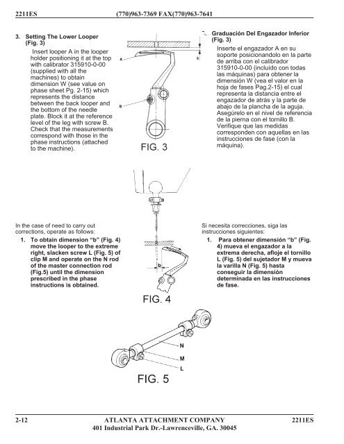
3. Setting The Lower Looper<br />
(Fig. 3)<br />
Insert looper A in the looper<br />
holder positioning it at the top<br />
with calibrator 315910-0-00<br />
(supplied with all the<br />
machines) to obtain<br />
dimension W (see value on<br />
phase sheet Pg. 2-15) which<br />
represents the distance<br />
between the back looper and<br />
the bottom of the needle<br />
plate. Block it at the reference<br />
level of the leg with screw B.<br />
Check that the measurements<br />
correspond with those in the<br />
phase instructions (attached<br />
to the machine).<br />
In the case of need to carry out<br />
corrections, operate as follows:<br />
1. To obtain dimension “b” (Fig. 4)<br />
move the looper to the extreme<br />
right, slacken screw L (Fig. 5) of<br />
clip M and operate on the N rod<br />
of the master connection rod<br />
(Fig.5) until the dimension<br />
prescribed in the phase<br />
instructions is obtained.<br />
3. Graduación Del Engazador Inferior<br />
(Fig. 3)<br />
Inserte el engazador A en su<br />
soporte posicionandolo en la parte<br />
de arriba con el calibrador<br />
315910-0-00 (incluído con todas<br />
las máquinas) para obtener la<br />
dimensión W (vea el valor en la<br />
hoja de fases Pag.2-15) el cual<br />
representa la distancia entre el<br />
engazador de atrás y la parte de<br />
abajo de la plancha de la aguja.<br />
Asegúrelo en el nivel de referencia<br />
de la pierna con el tornillo B.<br />
Verifique que las medidas<br />
corresponden con aquellas en las<br />
instrucciones de fase (con la<br />
máquina).<br />
Si necesita correcciones, siga las<br />
instrucciones siguientes:<br />
1. Para obtener dimensión “b” (Fig.<br />
4) mueva el engazador a la<br />
extrema derecha, afloje el tornillo<br />
L (Fig. 5) del sujetador M y mueva<br />
la varilla N (Fig. 5) hasta<br />
conseguir la dimensión<br />
determinada en las instrucciones<br />
de fase.<br />
2-12 ATLANTA ATTACHMENT COMPANY 2<strong>211</strong>ES<br />
401 Industrial Park Dr.-Lawrenceville, GA. 30045