211-125A Table Assembly - Atlanta Attachment Co.
211-125A Table Assembly - Atlanta Attachment Co.
211-125A Table Assembly - Atlanta Attachment Co.

You also want an ePaper? Increase the reach of your titles
YUMPU automatically turns print PDFs into web optimized ePapers that Google loves.
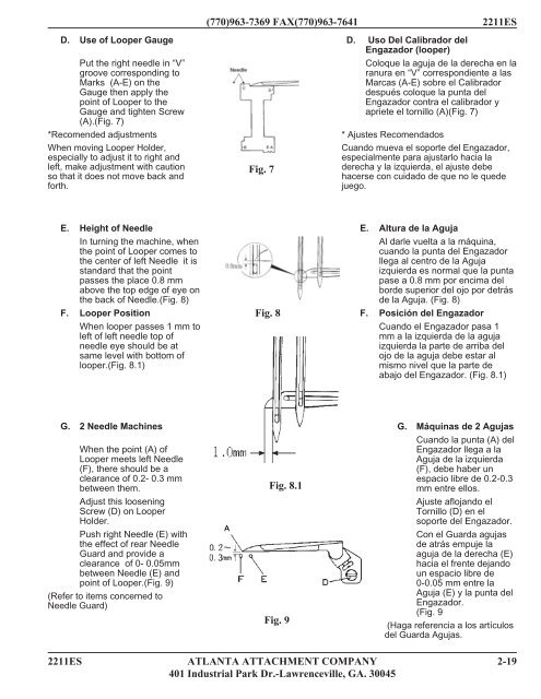
D. Use of Looper Gauge<br />
Put the right needle in “V”<br />
groove corresponding to<br />
Marks (A-E) on the<br />
Gauge then apply the<br />
point of Looper to the<br />
Gauge and tighten Screw<br />
(A).(Fig. 7)<br />
*Recomended adjustments<br />
When moving Looper Holder,<br />
especially to adjust it to right and<br />
left, make adjustment with caution<br />
so that it does not move back and<br />
forth.<br />
E. Height of Needle<br />
In turning the machine, when<br />
the point of Looper comes to<br />
the center of left Needle it is<br />
standard that the point<br />
passes the place 0.8 mm<br />
above the top edge of eye on<br />
the back of Needle.(Fig. 8)<br />
F. Looper Position<br />
When looper passes 1 mm to<br />
left of left needle top of<br />
needle eye should be at<br />
same level with bottom of<br />
looper.(Fig. 8.1)<br />
G. 2 Needle Machines<br />
When the point (A) of<br />
Looper meets left Needle<br />
(F), there should be a<br />
clearance of 0.2- 0.3 mm<br />
between them.<br />
Adjust this loosening<br />
Screw (D) on Looper<br />
Holder.<br />
Push right Needle (E) with<br />
the effect of rear Needle<br />
Guard and provide a<br />
clearance of 0- 0.05mm<br />
between Needle (E) and<br />
point of Looper.(Fig. 9)<br />
(Refer to items concerned to<br />
Needle Guard)<br />
(770)963-7369 FAX(770)963-7641 2<strong>211</strong>ES<br />
Fig. 7<br />
Fig. 8<br />
Fig. 8.1<br />
Fig. 9<br />
D. Uso Del Calibrador del<br />
Engazador (looper)<br />
<strong>Co</strong>loque la aguja de la derecha en la<br />
ranura en “V” correspondiente a las<br />
Marcas (A-E) sobre el Calibrador<br />
después coloque la punta del<br />
Engazador contra el calibrador y<br />
apriete el tornillo (A)(Fig. 7)<br />
* Ajustes Recomendados<br />
Cuando mueva el soporte del Engazador,<br />
especialmente para ajustarlo hacia la<br />
derecha y la izquierda, el ajuste debe<br />
hacerse con cuidado de que no le quede<br />
juego.<br />
E. Altura de la Aguja<br />
Al darle vuelta a la máquina,<br />
cuando la punta del Engazador<br />
llega al centro de la Aguja<br />
izquierda es normal que la punta<br />
pase a 0.8 mm por encima del<br />
borde superior del ojo por detrás<br />
de la Aguja. (Fig. 8)<br />
F. Posición del Engazador<br />
Cuando el Engazador pasa 1<br />
mm a la izquierda de la aguja<br />
izquierda la parte de arriba del<br />
ojo de la aguja debe estar al<br />
mismo nivel que la parte de<br />
abajo del Engazador. (Fig. 8.1)<br />
G. Máquinas de 2 Agujas<br />
Cuando la punta (A) del<br />
Engazador llega a la<br />
Aguja de la izquierda<br />
(F), debe haber un<br />
espacio libre de 0.2-0.3<br />
mm entre ellos.<br />
Ajuste aflojando el<br />
Tornillo (D) en el<br />
soporte del Engazador.<br />
<strong>Co</strong>n el Guarda agujas<br />
de atrás empuje la<br />
aguja de la derecha (E)<br />
hacia el frente dejando<br />
un espacio libre de<br />
0-0.05 mm entre la<br />
Aguja (E) y la punta del<br />
Engazador.<br />
(Fig. 9<br />
(Haga referencia a los artículos<br />
del Guarda Agujas.<br />
2<strong>211</strong>ES ATLANTA ATTACHMENT COMPANY 2-19<br />
401 Industrial Park Dr.-Lawrenceville, GA. 30045