Create successful ePaper yourself
Turn your PDF publications into a flip-book with our unique Google optimized e-Paper software.
3. Technical data<br />
Filament voltage: ≤ 7.5 V AC/DC<br />
Anode voltage: 2000 V to 5000 V<br />
Anode current: typ. 0.18 mA at U A = 4000 V<br />
Beam current: 4 µA at U A = 4000 V<br />
Plate voltage: 50 to 350 V<br />
Glass bulb: 130 mm dia. approx.<br />
Total length: 260 mm approx.<br />
4. Operation<br />
To perform experiments using the Perrin tube,<br />
the following equipment is also required:<br />
1 Tube holder S 1014525<br />
1 High voltage power supply 5 kV (115 V, 50/60 Hz)<br />
1003309<br />
or<br />
1 High voltage power supply 5 kV (230 V, 50/60 Hz)<br />
1003310<br />
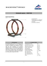
1 Helmholtz pair of coils S 1000611<br />
1 DC Power Supply 20 V, 5 A (115 V, 50/60 Hz)<br />
1003311<br />
or<br />
1 DC Power Supply 20 V, 5 A (230 V, 50/60 Hz)<br />
1003312<br />
1 Electroscope 1001027<br />
1 Analogue multimeter AM50 1003073<br />
4.1 Setting up the tube in the tube holder<br />
The tube should not be mounted or removed<br />
unless all power supplies are disconnected.<br />
• Press tube gently into the stock of the holder<br />
and push until the pins are fully inserted. Take<br />
note of the unique position of the guide pin.<br />
4.2 Removing the tube from the tube holder<br />
• To remove the tube, apply pressure with the<br />
middle finger on the guide pin and the thumb<br />
on the tail-stock until the pins loosen, then<br />
pull out the tube.<br />
5. Example experiments<br />
5.1 Evidence of the particle nature of cathode<br />
beam and establishment of their polarity<br />
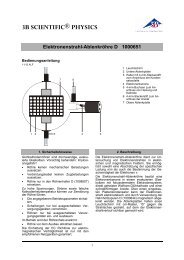
• Set up the experiment as in fig. 1.<br />
• Apply a voltage to the anode between 2 kV<br />
and 5 kV.<br />
On the fluorescent screen the cathode beams<br />
are visible as a round spot.<br />
• Slowly increase the coil current until the<br />
electron beam is deflected into the Faraday<br />
cage. If necessary, reverse the direction of<br />
the coil current and turn the tube in the tube<br />
holder so that the beam alls within the end<br />
of the Faraday cage.<br />
The electroscope will open to indicate the presence<br />
of a charge.<br />
• Turn off the voltage to the heater filament<br />
and the anode.<br />
The electroscope remains open.<br />
If the charge on the Faraday cage were due to<br />
the cathode beam being some kind of wave<br />
radiation, the charge should disappear when the<br />
filament ceases to radiate. Because the experiment<br />
shows that the charge remains on the<br />
cage when the filament is cold, the conclusion<br />
must be that the beam comprises some constituent<br />
of matter which is electrically charged.<br />
These particles are called electrons.<br />
The negative polarity of the cathode beam can be<br />
demonstrated if the electroscope is charged by<br />
rubbing a plastic or a glass rod (so that they are<br />
negatively and positively charged respectively).<br />
5.2 Estimation of the specific electron charge<br />
e/m<br />
• Set up the experiment as in fig. 3.<br />
When the electron beam is deflected into the<br />
Faraday cage, the following applies to the specific<br />
charge e/m:<br />
e 2 ⋅ UA<br />
= (1)<br />
m ( B ⋅ r ) 2<br />
U A can be read out directly, the curvature radius r<br />
derives from the geometric data of the tube (bulb<br />
diameter 13 cm, Faraday cage at 45° to the<br />
beam axis) to r = 16 cm approx. (refer to fig. 2).<br />
With the coils at Helmholtz-geometry and the<br />
coil current I, the following applies to the magnetic<br />
flux density B of the magnetic field<br />
B<br />
3<br />
=<br />
2<br />
0<br />
⎛ 4 ⎞<br />
⎜ ⎟<br />
⎝ 5 ⎠<br />
μ ⋅ n<br />
⋅ ⋅ I = k ⋅ I<br />
R<br />
(2)<br />
with k = at good approximation 4.2 mT/A, n = 320<br />
(no. of turns) and R = 68 mm (coil radius).<br />
• Substitute U A , r and B in equation 1 and<br />
calculate e/m.<br />
5.3 Deflection in crossed magnetic alternating<br />
fields (Lissajous figures)<br />
The following equipment is also required:<br />
1 Auxiliary coil 1000645<br />
1 AC/DC power supply 12 V, 3 A (115 V, 50/60 Hz)<br />
1002775<br />
or<br />
1 AC/DC power supply 12 V, 3 A (230 V, 50/60 Hz)<br />
1002776<br />
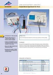
1 Function generator FG100 (115 V, 50/60 Hz)<br />
1009956<br />
or<br />
1 Function generator FG100 (230 V, 50/60 Hz)<br />
1009957<br />
• Set up the experiment as in fig. 5.<br />
• Place the auxiliary coil on the tube holder as<br />
in fig. 4.<br />
2