
You also want an ePaper? Increase the reach of your titles
YUMPU automatically turns print PDFs into web optimized ePapers that Google loves.
• Connect the auxiliary coil to the alternating<br />
current source.<br />
• Connect the Helmholtz coils to the function<br />
generator and choose a sinusoidal wave form.<br />
• Apply a voltage to the anode between 2 kV<br />
and 5 kV.<br />
• Apply an alternating voltage up to 15 V to<br />
the auxiliary coil and observe the horizontal<br />
deflection.<br />
• Set a frequency of e.g. 50 Hz at the function<br />
generator, vary the amplitude of the sinesignal<br />
and observe the Lissajous figures on<br />
the fluorescent screen.<br />
5.4 Deflection in collinear alternating magnetic<br />
and electric fields<br />
The following equipment is also required:<br />
1 Function generator FG100 (115 V, 50/60 Hz)<br />
1009956<br />
or<br />
1 Function generator FG100 (230 V, 50/60 Hz)<br />
1009957<br />
1 AC Power supply unit with an output of up to<br />
250 V AC<br />
Note: In this set-up the anode must be connected<br />
to ground potential!<br />
Caution! Contact-hazardous voltages may be<br />
present at the connection field of the tube<br />
holder.<br />
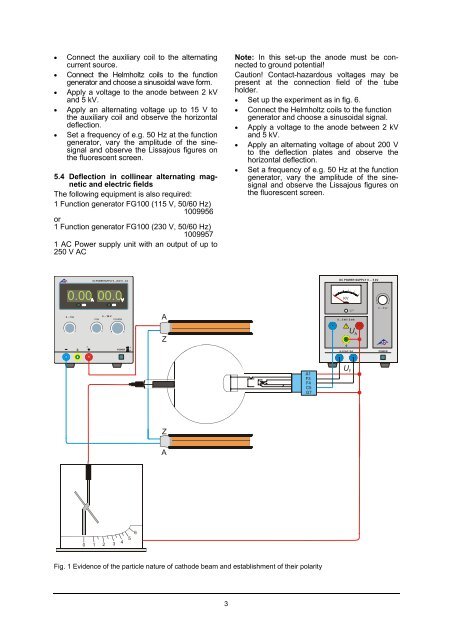
• Set up the experiment as in fig. 6.<br />
• Connect the Helmholtz coils to the function<br />
generator and choose a sinusoidal signal.<br />
• Apply a voltage to the anode between 2 kV<br />
and 5 kV.<br />
• Apply an alternating voltage of about 200 V<br />
to the deflection plates and observe the<br />
horizontal deflection.<br />
• Set a frequency of e.g. 50 Hz at the function<br />
generator, vary the amplitude of the sinesignal<br />
and observe the Lissajous figures on<br />
the fluorescent screen.<br />
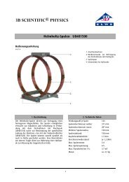
DC POWER SUPPLY 0 ... 5 kV<br />
1<br />
2<br />
3<br />
4<br />
0<br />
KV<br />
5<br />
A<br />
0 ... 5 kV<br />
Z<br />
U F<br />
U A<br />
Z<br />
A<br />
0 1 2 3 4 5 6<br />
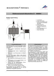
Fig. 1 Evidence of the particle nature of cathode beam and establishment of their polarity<br />
3